ESRF Operation Status Report Accelerator Upgrade Programme P






- Slides: 30
ESRF Operation Status Report & Accelerator Upgrade Programme P. Raimondi On behalf of the Accelerator & Source Division Grenoble, November 25 - 2014
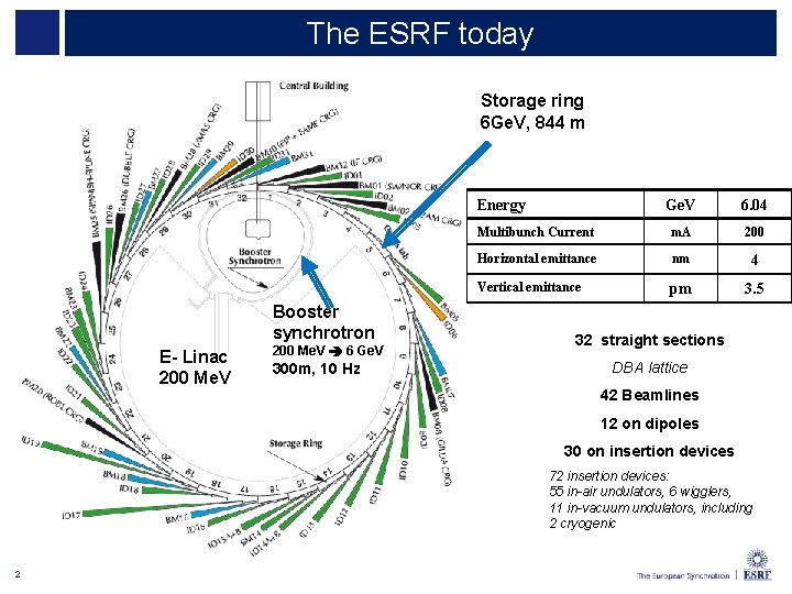
The ESRF today Storage ring 6 Ge. V, 844 m Energy Booster synchrotron E- Linac 200 Me. V 6 Ge. V 300 m, 10 Hz Ge. V 6. 04 Multibunch Current m. A 200 Horizontal emittance nm 4 Vertical emittance pm 3. 5 32 straight sections DBA lattice 42 Beamlines 12 on dipoles 30 on insertion devices 72 insertion devices: 55 in-air undulators, 6 wigglers, 11 in-vacuum undulators, including 2 cryogenic 2
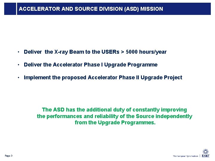
ACCELERATOR AND SOURCE DIVISION (ASD) MISSION • Deliver the X-ray Beam to the USERs > 5000 hours/year • Deliver the Accelerator Phase I Upgrade Programme • Implement the proposed Accelerator Phase II Upgrade Project The ASD has the additional duty of constantly improving the performances and reliability of the Source independently from the Upgrade Programmes. 3 Page 3
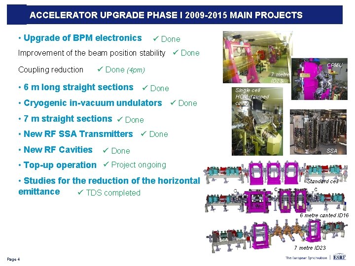
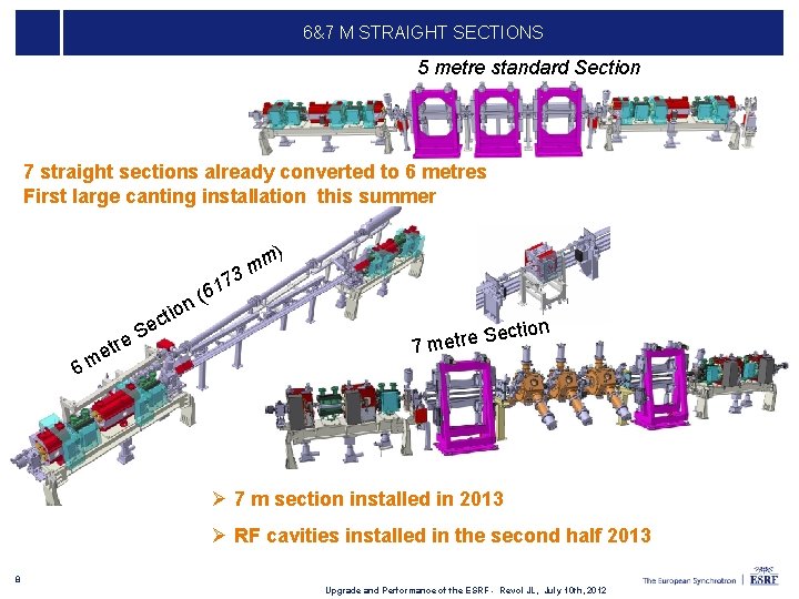
ACCELERATOR UPGRADE PHASE I 2009 -2015 MAIN PROJECTS • Upgrade of BPM electronics ü Done Improvement of the beam position stability ü Done Coupling reduction CPMU ü Done (4 pm) • 6 m long straight sections ü Done • Cryogenic in-vacuum undulators ü Done 7 metre ID 23 Single cell HOM damped cavity • 7 m straight sections ü Done • New RF SSA Transmitters ü Done • New RF Cavities ü Done SSA • Top-up operation ü Project ongoing • Studies for the reduction of the horizontal emittance ü TDS completed Standard cell 6 metre canted ID 16 7 metre ID 23 4 Page 4
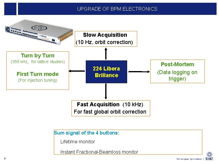
UPGRADE OF BPM ELECTRONICS Slow Acquisition (10 Hz, orbit correction) Turn by Turn (355 k. Hz, for lattice studies) First Turn mode (For injection tuning) 224 Libera Brillance Fast Acquisition (10 k. Hz) For fast global orbit correction Sum signal of the 4 buttons: Lifetime monitor Instant Fractional-Beamloss monitor 5 Post-Mortem (Data logging on trigger)
COUPLING REDUCTION Maintaining low emittance during USM: 1 week delivery Current 200 m. A Vertical emittance 3. 5 pm 50 hours Lifetime @ Vertical Diffraction Limit reached routinely 6
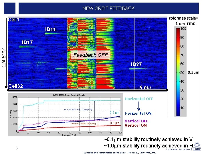
NEW ORBIT FEEDBACK Cell 1 rms ID 11 224 BPM ID 17 Feedback OFF ID 27 Cell 32 8 mn Horizontal OFF 7 2. 5 mm Horizontal ON 0. 9 mm Vertical OFF Vertical ON ~0. 1 mm stability routinely achieved in V ~1. 0 mm stability routinely achieved in H Upgrade and Performance of the ESRF - Revol JL, July 10 th, 2012
6&7 M STRAIGHT SECTIONS 5 metre standard Section 7 straight sections already converted to 6 metres First large canting installation this summer c tr e e. S e 6 m ( n o ti mm 3 17 ) 6 ection S e r t e 7 m Ø 7 m section installed in 2013 Ø RF cavities installed in the second half 2013 8 Upgrade and Performance of the ESRF - Revol JL, July 10 th, 2012
SINGLE CELL NC HOM DAMPED CAVITY • 9 MV with 12 to 18 cavities (4. 7 ± 0. 4 M ) • Planned operation at 300 m. A HOM absorbers: Ferrite loaded tapered ridges • Power capability to sustain up to 500 m. A 3 cavities operational in the SR • No HOM up to 1 A 352 MHz HOM dampers = ridge waveguides Based on 500 MHz BESSY, MLS, ALBA design Weihreter et al. ] ESRF 352. 2 MHz design: several improvements 9 Goal: RF distribution to create a new experimental station Prepare future upgrades [E.
SOLID STATE RF TRANSMITTERS Klystrons at l’ESRF 1. 3 MW -352 MHz Goal: Prevent klystron obsolescence Prepare future upgrades 2 five-cell cavities x 2 couplers 4 Waveguide switches to 4 water loads SY: Syn Booste chro r tron 75 k. W tower of 128 RF modules Booster RF : Four 150 k. W amplifiers in operation Replacing one 352. 2 MHz 1. 3 MW klystron booster transmitter SYRF now ready for Top. Up operation, (Electrical power reduced from 1200 to 400 k. W). 10
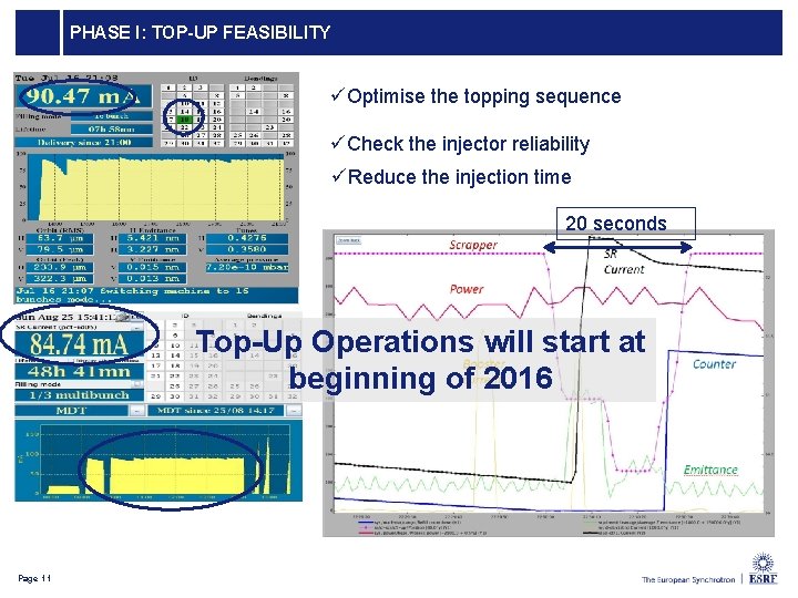
PHASE I: TOP-UP FEASIBILITY üOptimise the topping sequence üCheck the injector reliability üReduce the injection time 20 seconds Top-Up Operations will start at beginning of 2016 11 Page 11
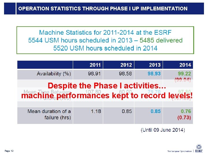
OPERATION STATISTICS THROUGH PHASE I UP IMPLEMENTATION Despite the Phase I activities… machine performances kept to record levels! 12 Page 12
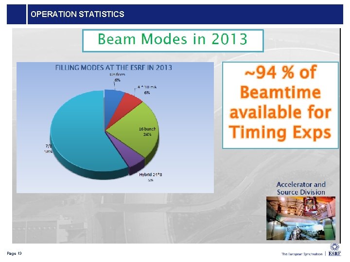
OPERATION STATISTICS Page 13
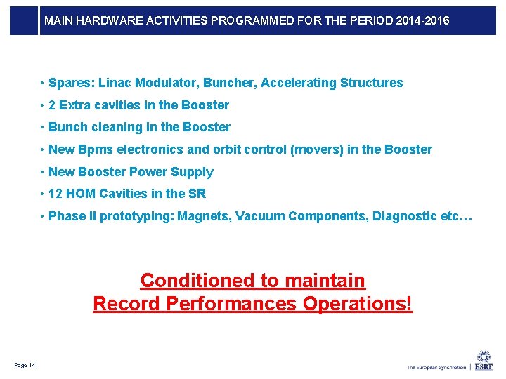
MAIN HARDWARE ACTIVITIES PROGRAMMED FOR THE PERIOD 2014 -2016 • Spares: Linac Modulator, Buncher, Accelerating Structures • 2 Extra cavities in the Booster • Bunch cleaning in the Booster • New Bpms electronics and orbit control (movers) in the Booster • New Booster Power Supply • 12 HOM Cavities in the SR • Phase II prototyping: Magnets, Vacuum Components, Diagnostic etc… Conditioned to maintain Record Performances Operations! Page 14
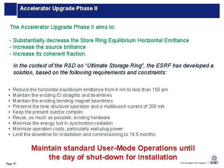
Accelerator Upgrade Phase II The Accelerator Upgrade Phase II aims to: - Substantially decrease the Store Ring Equilibrium Horizontal Emittance - Increase the source brilliance - Increase its coherent fraction. In the context of the R&D on “Ultimate Storage Ring”, the ESRF has developed a solution, based on the following requirements and constraints: • • • Reduce the horizontal equilibrium emittance from 4 nm to less than 150 pm Maintain the existing ID straights and beamlines Maintain the existing bending magnet beamlines Preserve the time structure operation and a multibunch current of 200 m. A Keep the present injector complex Reuse, as much as possible, existing hardware Minimize the energy lost in synchrotron radiation Minimize operation costs, particularly wall-plug power Limit the downtime for installation and commissioning to 19. 5 months. Maintain standard User-Mode Operations until the day of shut-down for installation 15 Page 15
LOW EMITTANCE RINGS TREND Based on 1980 Know. How Based on state of the art technologies Sirius APS SPring 8 Existing machines In Construction Advanced Projects Concept stage Several facilities will implement Low Horizontal Emittance Lattices by the next decade 16 16 Page
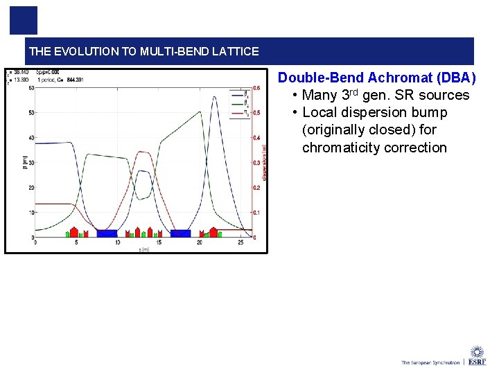
THE EVOLUTION TO MULTI-BEND LATTICE Double-Bend Achromat (DBA) • Many 3 rd gen. SR sources • Local dispersion bump (originally closed) for chromaticity correction 17 Andrea Franchi Optimization of dynamic aperture for the ESRF upgrade
THE EVOLUTION TO MULTI-BEND LATTICE Double-Bend Achromat (DBA) • Many 3 rd gen. SR sources • Local dispersion bump (originally closed) for chromaticity correction Multi-Bend Achromat (MBA) • MAX IV and other USRs • No dispersion bump, its value is a trade-off between emittance and sextupoles (DA) 18 Andrea Franchi Optimization of dynamic aperture for the ESRF upgrade
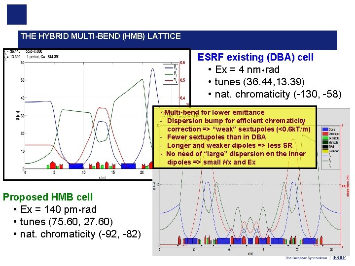
THE HYBRID MULTI-BEND (HMB) LATTICE ESRF existing (DBA) cell • Ex = 4 nm rad • tunes (36. 44, 13. 39) • nat. chromaticity (-130, -58) - Multi-bend for lower emittance - Dispersion bump for efficient chromaticity correction => “weak” sextupoles (<0. 6 k. T/m) - Fewer sextupoles than in DBA - Longer and weaker dipoles => less SR - No need of “large” dispersion on the inner dipoles => small Hx and Ex Proposed HMB cell • Ex = 140 pm rad • tunes (75. 60, 27. 60) • nat. chromaticity (-92, -82) 19 Andrea Franchi Optimization of dynamic aperture for the ESRF upgrade
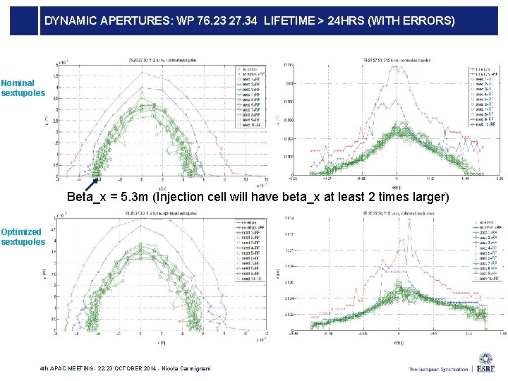
DYNAMIC APERTURES: WP 76. 23 27. 34 LIFETIME > 24 HRS (WITH ERRORS) Nominal sextupoles Beta_x = 5. 3 m (Injection cell will have beta_x at least 2 times larger) Optimized sextupoles 4 th APAC MEETING - 22 -23 OCTOBER 2014 - Nicola Carmignani
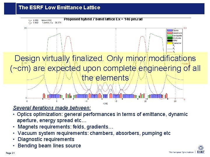
The ESRF Low Emittance Lattice Proposed hybrid 7 bend lattice Ex = 146 pm. rad Design virtually finalized. Only minor modifications (~cm) are expected upon complete engineering of all the elements Several iterations made between: • Optics optimization: general performances in terms of emittance, dynamic aperture, energy spread etc… • Magnets requirements: felds, gradients… • Vacuum system requirements: chambers, absorbers, pumping etc • Diagnostic requirements • Bending beam lines source 21 Page 21
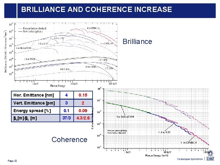
Coherence BRILLIANCE Improved AND COHERENCE INCREASE Brilliance Hor. Emittance [nm] 4 0. 15 Vert. Emittance [pm] 3 2 Energy spread [%] 0. 1 0. 09 bx[m]/bz [m] 37/3 4. 3/2. 6 Coherence 22 Page 22
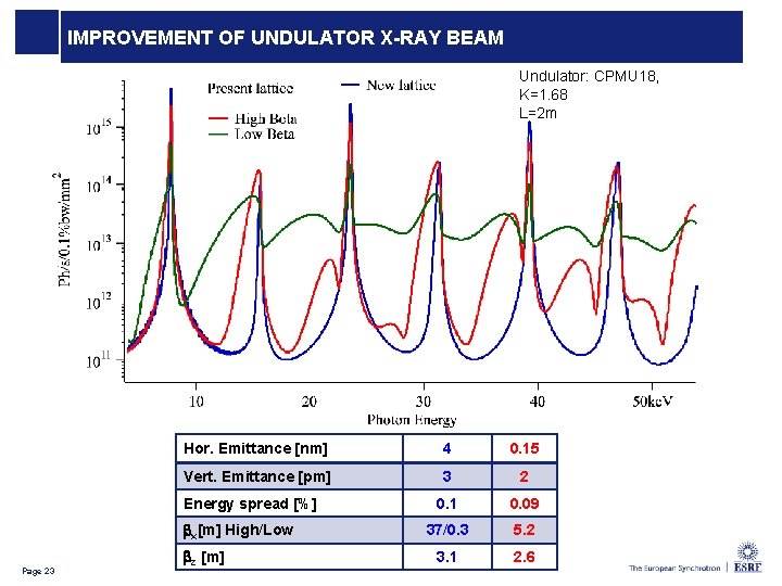
IMPROVEMENT OF UNDULATOR X-RAY BEAM Undulator: CPMU 18, K=1. 68 L=2 m Hor. Emittance [nm] 4 0. 15 Vert. Emittance [pm] 3 2 0. 1 0. 09 37/0. 3 5. 2 3. 1 2. 6 Energy spread [%] bx[m] High/Low 23 Page 23 bz [m]
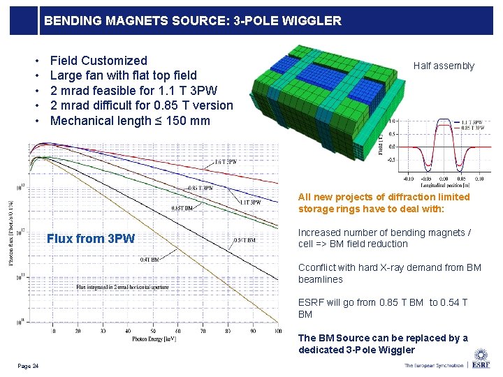
BENDING MAGNETS SOURCE: 3 -POLE WIGGLER • • • Field Customized Large fan with flat top field 2 mrad feasible for 1. 1 T 3 PW 2 mrad difficult for 0. 85 T version Mechanical length ≤ 150 mm Half assembly All new projects of diffraction limited storage rings have to deal with: Flux from 3 PW Increased number of bending magnets / cell => BM field reduction Cconflict with hard X-ray demand from BM beamlines ESRF will go from 0. 85 T BM to 0. 54 T BM The BM Source can be replaced by a dedicated 3 -Pole Wiggler Page 24
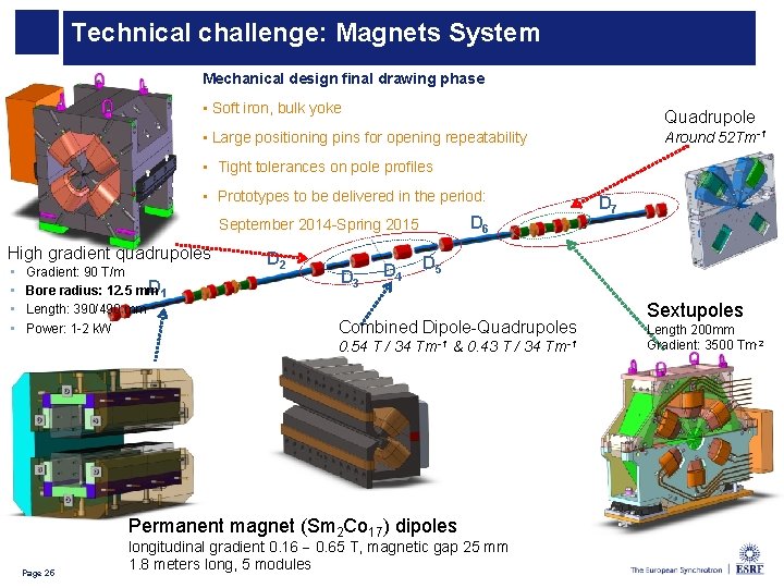
Technical challenge: Magnets System Mechanical design final drawing phase • Soft iron, bulk yoke Quadrupole • Large positioning pins for opening repeatability Around 52 Tm-1 • Tight tolerances on pole profiles • Prototypes to be delivered in the period: D 6 September 2014 -Spring 2015 High gradient quadrupoles • • Gradient: 90 T/m D 1 Bore radius: 12. 5 mm Length: 390/490 mm Power: 1 -2 k. W D 2 D 3 D 4 D 5 Combined Dipole-Quadrupoles 0. 54 T / 34 Tm-1 & 0. 43 T / 34 Permanent magnet (Sm 2 Co 17) dipoles 25 Page 25 D 7 longitudinal gradient 0. 16 0. 65 T, magnetic gap 25 mm 1. 8 meters long, 5 modules Tm-1 Sextupoles Length 200 mm Gradient: 3500 Tm-2
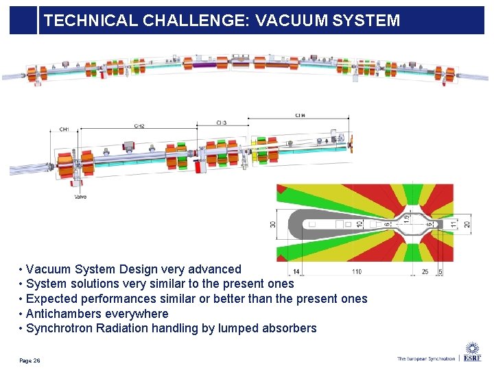
TECHNICAL CHALLENGE: VACUUM SYSTEM • Vacuum System Design very advanced • System solutions very similar to the present ones • Expected performances similar or better than the present ones • Antichambers everywhere • Synchrotron Radiation handling by lumped absorbers 26 Page 26
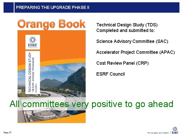
PREPARING THE UPGRADE PHASE II Technical Design Study (TDS) Completed and submitted to: Science Advisory Committee (SAC) Accelerator Project Committee (APAC) Cost Review Panel (CRP) ESRF Council All committees very positive to go ahead Page 27
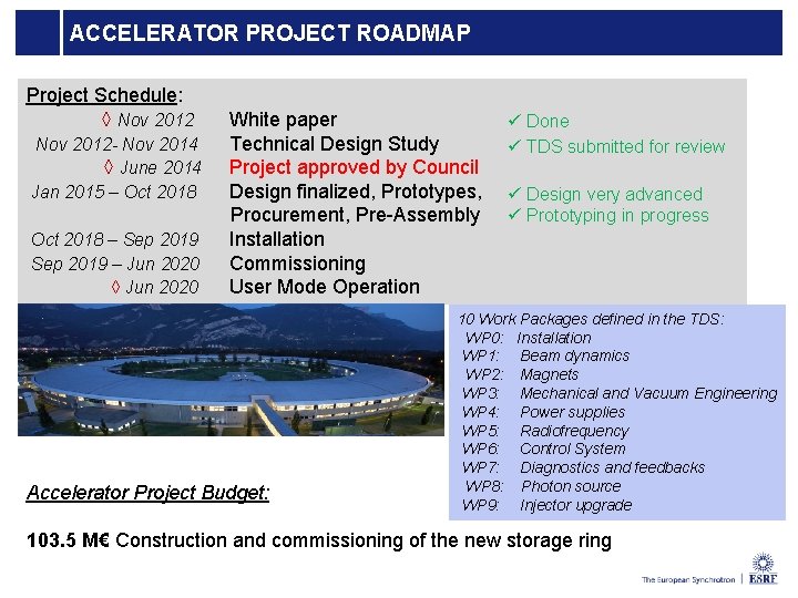
ACCELERATOR PROJECT ROADMAP Project Schedule: ◊ Nov 2012 - Nov 2014 ◊ June 2014 Jan 2015 – Oct 2018 – Sep 2019 – Jun 2020 ◊ Jun 2020 White paper Technical Design Study Project approved by Council Design finalized, Prototypes, Procurement, Pre-Assembly Installation Commissioning User Mode Operation Accelerator Project Budget: ü Done ü TDS submitted for review ü Design very advanced ü Prototyping in progress 10 Work Packages defined in the TDS: WP 0: Installation WP 1: Beam dynamics WP 2: Magnets WP 3: Mechanical and Vacuum Engineering WP 4: Power supplies WP 5: Radiofrequency WP 6: Control System WP 7: Diagnostics and feedbacks WP 8: Photon source WP 9: Injector upgrade 103. 5 M€ Construction and commissioning of the new storage ring 28
Conclusions Through the years ASD has delivered very high quality beam that have greatly contributed to maintain ESRF among the leaders of the SR facilities. Phase I has been the opportunity to further push the Source performances, the programme is being completed while maintaining the high standards beam delivery. Phase II will further expand the ESRF frontiers and will insure the continuation of its leadership in Science and in Synchrotron Accelerators for the next decade. 29 Page 29
MANY THANKS FOR YOUR ATTENTION Page 30