Toward a Diffraction Limited Light Source The ESRF









- Slides: 36
Toward a Diffraction Limited Light Source: The ESRF Storage Ring Upgrade Varenna, July 9 -11 2015 Pantaleo Raimondi On behalf of the Accelerator Project Phase II Team
ACCELERATOR ESRF TODAYAND SOURCE DIVISION (ASD) MISSION Storage ring 6 Ge. V, 844 m Energy Booster synchrotron E- Linac 200 Me. V 6 Ge. V 300 m, 10 Hz Ge. V 6. 04 Multibunch Current m. A 200 Horizontal emittance nm 4 Vertical emittance pm 3. 5 32 straight sections DBA lattice 42 Beamlines 12 on dipoles 30 on insertion devices 72 insertion devices: 55 in-air undulators, 6 wigglers, 11 in-vacuum undulators, including 2 cryogenic 2
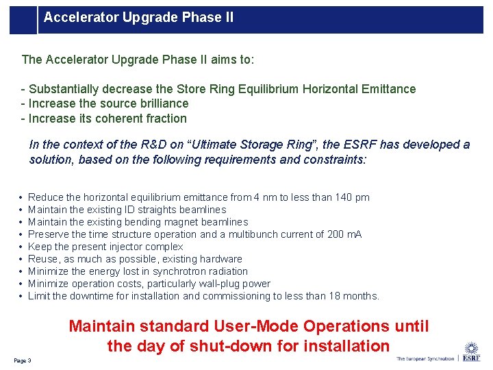
Accelerator Upgrade Phase II The Accelerator Upgrade Phase II aims to: - Substantially decrease the Store Ring Equilibrium Horizontal Emittance - Increase the source brilliance - Increase its coherent fraction In the context of the R&D on “Ultimate Storage Ring”, the ESRF has developed a solution, based on the following requirements and constraints: • • • Reduce the horizontal equilibrium emittance from 4 nm to less than 140 pm Maintain the existing ID straights beamlines Maintain the existing bending magnet beamlines Preserve the time structure operation and a multibunch current of 200 m. A Keep the present injector complex Reuse, as much as possible, existing hardware Minimize the energy lost in synchrotron radiation Minimize operation costs, particularly wall-plug power Limit the downtime for installation and commissioning to less than 18 months. Maintain standard User-Mode Operations until the day of shut-down for installation 3 Page 3
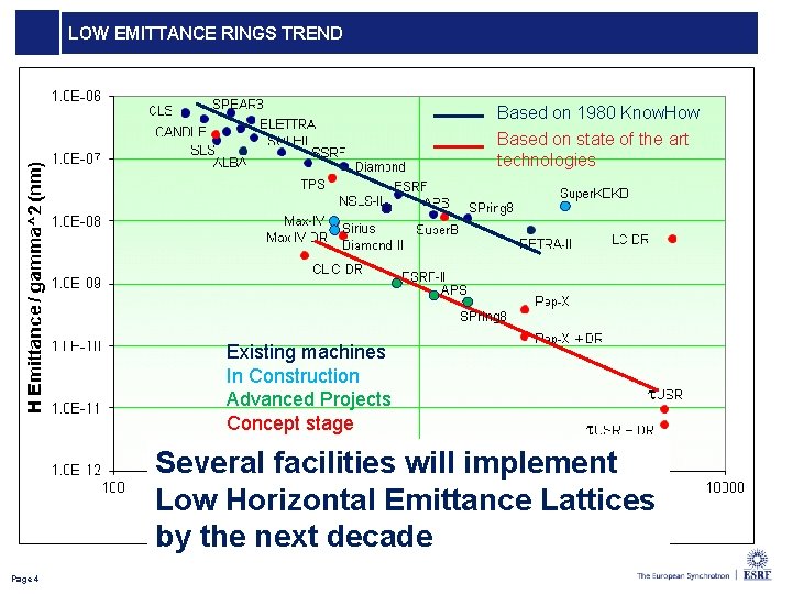
LOW EMITTANCE RINGS TREND Based on 1980 Know. How Based on state of the art technologies Sirius APS SPring 8 Existing machines In Construction Advanced Projects Concept stage Several facilities will implement Low Horizontal Emittance Lattices by the next decade 4 Page 4
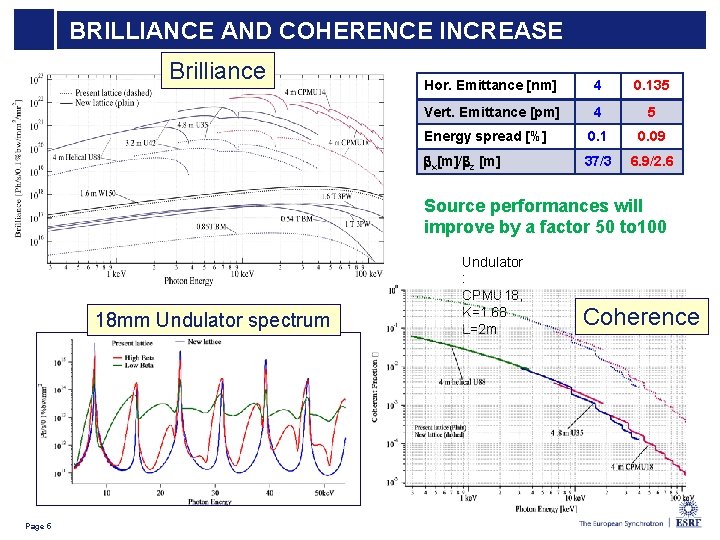
Coherence BRILLIANCE Improved AND COHERENCE INCREASE Brilliance Hor. Emittance [nm] 4 0. 135 Vert. Emittance [pm] 4 5 Energy spread [%] 0. 1 0. 09 bx[m]/bz [m] 37/3 6. 9/2. 6 Source performances will improve by a factor 50 to 100 18 mm Undulator spectrum 5 Page 5 Undulator : CPMU 18, K=1. 68 L=2 m Coherence
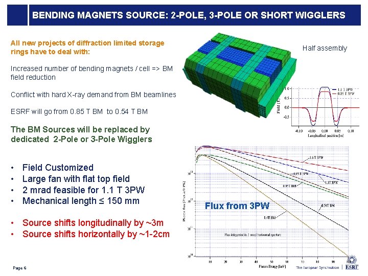
BENDING MAGNETS SOURCE: 2 -POLE, 3 -POLE OR SHORT WIGGLERS All new projects of diffraction limited storage rings have to deal with: Half assembly Increased number of bending magnets / cell => BM field reduction Conflict with hard X-ray demand from BM beamlines ESRF will go from 0. 85 T BM to 0. 54 T BM The BM Sources will be replaced by dedicated 2 -Pole or 3 -Pole Wigglers • • Field Customized Large fan with flat top field 2 mrad feasible for 1. 1 T 3 PW Mechanical length ≤ 150 mm • Source shifts longitudinally by ~3 m • Source shifts horizontally by ~1 -2 cm Page 6 Flux from 3 PW
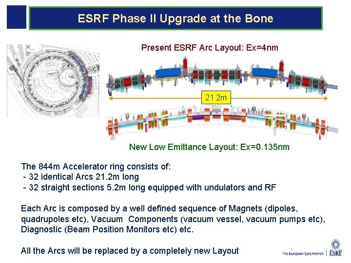
UP PI: Preparing the UP Phase II ESRF Phase II Upgrade at the Bone Present ESRF Arc Layout: Ex=4 nm 21. 2 m New Low Emittance Layout: Ex=0. 135 nm The 844 m Accelerator ring consists of: - 32 identical Arcs 21. 2 m long - 32 straight sections 5. 2 m long equipped with undulators and RF Each Arc is composed by a well defined sequence of Magnets (dipoles, quadrupoles etc), Vacuum Components (vacuum vessel, vacuum pumps etc), Diagnostic (Beam Position Monitors etc) etc. All the Arcs will be replaced by a completely new Layout
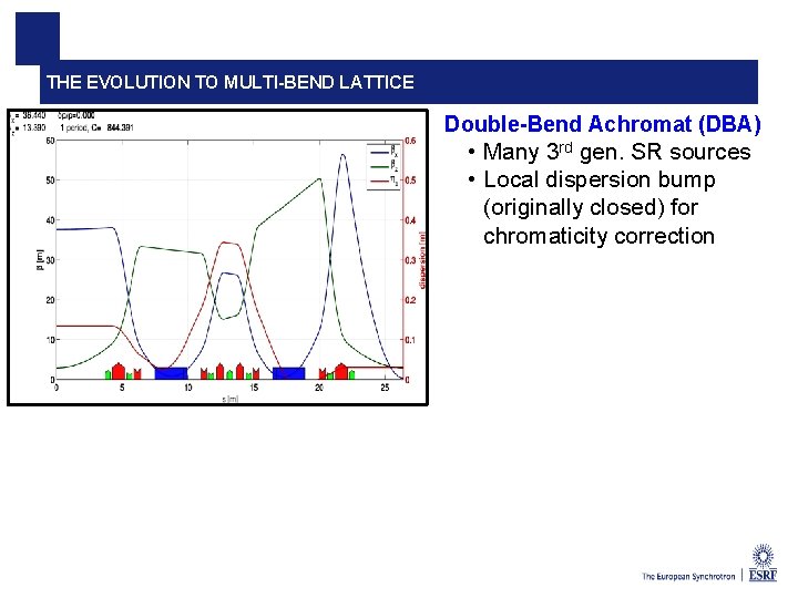
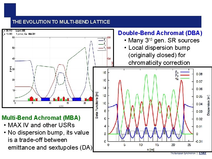
THE EVOLUTION TO MULTI-BEND LATTICE Double-Bend Achromat (DBA) • Many 3 rd gen. SR sources • Local dispersion bump (originally closed) for chromaticity correction 8 Andrea Franchi Optimization of dynamic aperture for the ESRF upgrade
THE EVOLUTION TO MULTI-BEND LATTICE Double-Bend Achromat (DBA) • Many 3 rd gen. SR sources • Local dispersion bump (originally closed) for chromaticity correction Multi-Bend Achromat (MBA) • MAX IV and other USRs • No dispersion bump, its value is a trade-off between emittance and sextupoles (DA) 9 Andrea Franchi Optimization of dynamic aperture for the ESRF upgrade
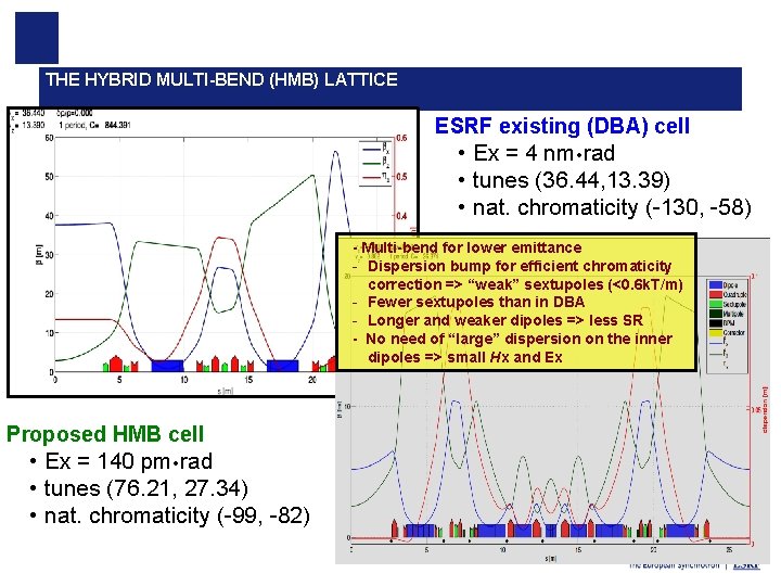
THE HYBRID MULTI-BEND (HMB) LATTICE ESRF existing (DBA) cell • Ex = 4 nm rad • tunes (36. 44, 13. 39) • nat. chromaticity (-130, -58) - Multi-bend for lower emittance - Dispersion bump for efficient chromaticity correction => “weak” sextupoles (<0. 6 k. T/m) - Fewer sextupoles than in DBA - Longer and weaker dipoles => less SR - No need of “large” dispersion on the inner dipoles => small Hx and Ex Proposed HMB cell • Ex = 140 pm rad • tunes (76. 21, 27. 34) • nat. chromaticity (-99, -82) 10 Andrea Franchi Optimization of dynamic aperture for the ESRF upgrade
LATTICE EVOLUTION: S 28 B OPTICAL FUNCTIONS Natural equilibrium emittance: εx 0 = 134 pm Emittances with 5 pm coupled into the vertical plane and 0. 5 MV radiation losses from IDs: εx = 107 pm εz = 5 pm Page 11 1 st MAC MEETING – 14 -15 April L. Farvacque
INJECTION CELL: S 28 B • 2 quadrupoles in the straight section, • The global phase advance is still strictly identical to the standard cell, • However the tuning of the whole cell is slightly different, giving more flexibility for the injection tuning. Septum location Page 12 1 st MAC MEETING – 14 -15 April L. Farvacque
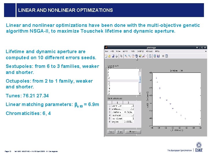
LINEAR AND NONLINEAR OPTIMIZATIONS Linear and nonlinear optimizations have been done with the multi-objective genetic algorithm NSGA-II, to maximize Touschek lifetime and dynamic aperture. Lifetime and dynamic aperture are computed on 10 different errors seeds. Sextupoles: from 6 to 3 families, weaker and shorter. Octupoles: from 2 to 1 family, weaker and shorter. Tunes: 76. 21 27. 34 Linear matching parameters: bx ID = 6. 9 m Chromaticities: 6, 4 Page 13 1 st MAC MEETING – 14 -15 April 2015 - N. Carmignani
LIFETIME OF S 28 B S 28 A DA -8. 1 mm@S 3 TLT ~ 13 h. S 28 B DA -10 mm@S 3 TLT ~ 21 h ey=5 pm ESRF Upgra de Page 14 1 st MAC MEETING – 14 -15 April 2015 - N. Carmignani 7/8 64 h multibunch 21 h 16 bunch 6 h 2. 1 h 4 bunch 4 h 1. 4 h
COLLIMATION OPTIMIZATION TO DECREASE LOSSES IN THE IDS Page 15 1 st MAC MEETING – 14 -15 April 2015 - N. Carmignani
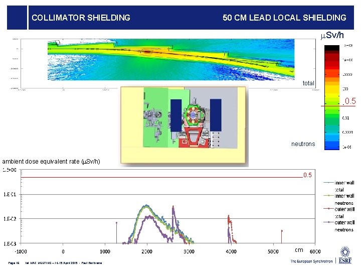
COLLIMATOR SHIELDING 50 CM LEAD LOCAL SHIELDING m. Sv/h total 0. 5 neutrons ambient dose equivalent rate (m. Sv/h) 0. 5 cm Page 16 1 st MAC MEETING – 14 -15 April 2015 - Paul Berkvens
The ESRF Low Emittance Lattice Proposed hybrid 7 bend lattice Ex = 146 pm. rad From Concepts to a Real Machine Several iterations made between: • Optics optimization: general performances in terms of emittance, dynamic aperture, energy spread etc… • Magnets requirements: felds, gradients… • Vacuum system requirements: chambers, absorbers, pumping etc • Diagnostic requirements • Bending beam lines source 17 Page 17
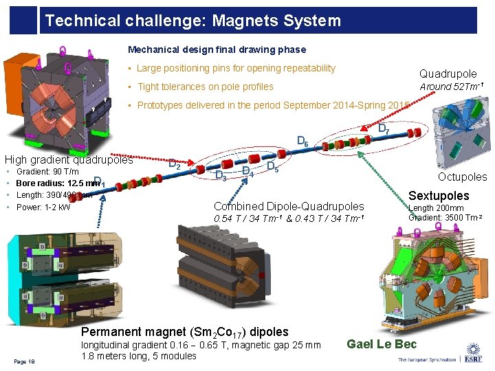
Technical challenge: Magnets System Mechanical design final drawing phase • Large positioning pins for opening repeatability Quadrupole • Tight tolerances on pole profiles Around 52 Tm-1 • Prototypes delivered in the period September 2014 -Spring 2015 D 7 D 6 High gradient quadrupoles • • Gradient: 90 T/m D 1 Bore radius: 12. 5 mm Length: 390/490 mm Power: 1 -2 k. W D 2 D 3 D 4 D 5 Octupoles Combined Dipole-Quadrupoles 0. 54 T / 34 Tm-1 & 0. 43 T / 34 Permanent magnet (Sm 2 Co 17) dipoles 18 Page 18 longitudinal gradient 0. 16 0. 65 T, magnetic gap 25 mm 1. 8 meters long, 5 modules Tm-1 Sextupoles Length 200 mm Gradient: 3500 Tm-2 Gael Le Bec
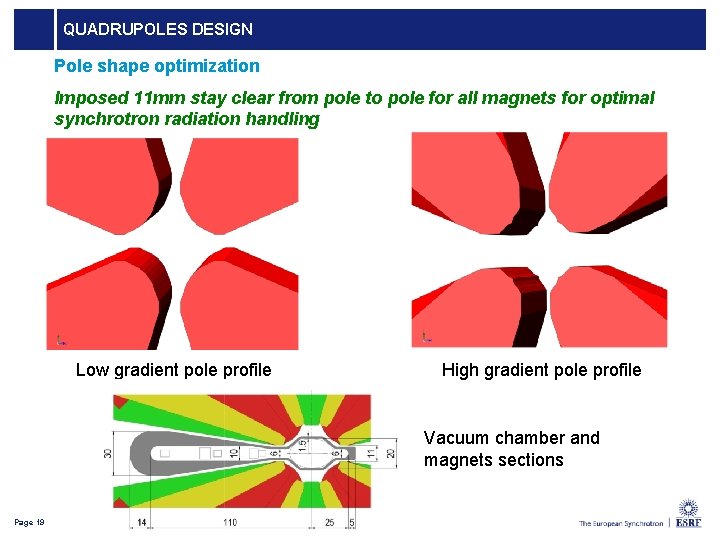
QUADRUPOLES DESIGN Pole shape optimization Imposed 11 mm stay clear from pole to pole for all magnets for optimal synchrotron radiation handling Low gradient pole profile High gradient pole profile Vacuum chamber and magnets sections Page 19
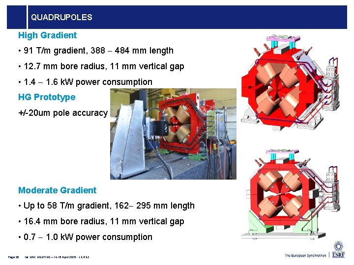
QUADRUPOLES High Gradient • 91 T/m gradient, 388 484 mm length • 12. 7 mm bore radius, 11 mm vertical gap • 1. 4 1. 6 k. W power consumption HG Prototype +/-20 um pole accuracy Moderate Gradient • Up to 58 T/m gradient, 162 295 mm length • 16. 4 mm bore radius, 11 mm vertical gap • 0. 7 1. 0 k. W power consumption Page 20 1 st MAC MEETING – 14 -15 April 2015 - LE BEC
DIPOLE WITH LONGITUDINAL GRADIENT Specifications • 0. 17 0. 67 T field • 5 modules of 357 mm each • Larger gap for the low field module • Allows the installation of an absorber Engineering design • Final drawings produced Prototyping • Final prototype to be build in the coming months Measured field integral homogeneity (one module) Page 21 1 st MAC MEETING – 14 -15 April 2015 - LE BEC
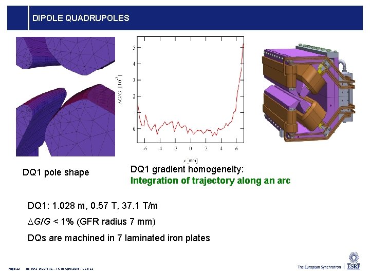
DIPOLE QUADRUPOLES DQ 1 pole shape DQ 1 gradient homogeneity: Integration of trajectory along an arc DQ 1: 1. 028 m, 0. 57 T, 37. 1 T/m DG/G < 1% (GFR radius 7 mm) DQs are machined in 7 laminated iron plates Page 22 1 st MAC MEETING – 14 -15 April 2015 - LE BEC
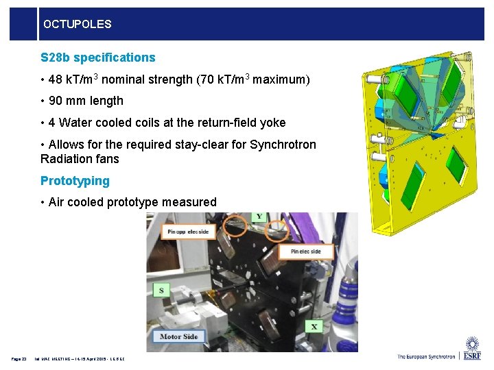
OCTUPOLES S 28 b specifications • 48 k. T/m 3 nominal strength (70 k. T/m 3 maximum) • 90 mm length • 4 Water cooled coils at the return-field yoke • Allows for the required stay-clear for Synchrotron Radiation fans Prototyping • Air cooled prototype measured Page 23 1 st MAC MEETING – 14 -15 April 2015 - LE BEC
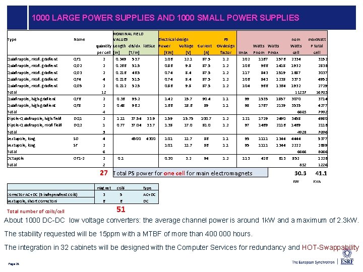
1000 LARGE POWER SUPPLIES AND 1000 SMALL POWER SUPPLIES Type Quadrupole, mod. gradient Total Quadrupole, high gradient Total Dipole-Quadrupole, high field Dipole-Quadrupole, mod field Total Sextupole, long Total Octupole Total Name QF 1 QD 2 QD 3 QF 4 QD 5 QF 6 QF 8 DQ 1 DQ 2 SD SF OF 1 -2 quantity per cell 2 2 2 4 2 1 3 4 2 6 2 2 NOMINAL FIELD VALUES Electrical design Length d. B/dx lattice Power Voltage Current [m] [T/m] [k. W] [V] [A] 0. 349 53. 7 1. 06 12. 1 87. 5 0. 266 51. 5 0. 86 9. 8 87. 5 0. 216 46. 5 0. 74 8. 4 87. 5 0. 216 51. 5 0. 74 8. 4 87. 5 0. 212 52. 5 0. 86 9. 8 87. 5 0. 36 95. 2 1. 42 15. 7 90. 48 96. 2 1. 66 18. 6 89 1. 11 37. 54 33. 9 1. 59 15. 75 100. 77 37. 04 33. 7 1. 38 17. 0 81. 0 4500 4300 1. 01 11. 7 86 0. 1 0. 30 3. 2 94 PS OVdesign factor 1. 2 1. 2 1. 1 1. 2 Imax 102 106 117 106 104 99 98 121 97 95 95 113 27 Total PS power for one cell for main electromagnets Watts Pnom Pmax 1167 1576 966 1418 843 1519 843 1238 966 1364 1535 1857 1767 2139 1729 2490 1469 2116 1111 1344 426 613 nom max. Watts P total cell 2334 3152 1932 2836 1687 3037 3373 4952 1932 2729 11257 16705 3070 3714 3535 4277 6605 7992 3458 4980 1469 2116 4928 7096 4444 5377 2222 2689 6666 8066 852 1226 30. 3 KW corrector AC+DC (5 independent coils) Sextupole, short correctors Total number of coils/cell magnet 3 6 coils 5 6 51 41. 1 KVA type AC+DC DC About 1000 DC-DC low voltage converters: the average channel power is around 1 k. W and a maximum of 2. 3 k. W. The stability requested will be 15 ppm with a MTBF of more than 400 000 hours. The integration in 32 cabinets will be designed with the Computer Services for redundancy and HOT-Swappability Page 24
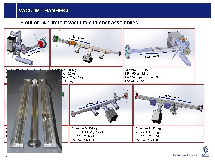
VACUUM CHAMBERS 6 out of 14 different vacuum chamber assemblies Beam axis ma Bea Chamber 1 with “cross”: 61 kg SIP 75 l/s: 22 kg RGA / lead protection: 15 kg TOTAL: 101 kg Beam axis Chamber 2: 99 kg SIP 75 l/s: 22 kg NEG 200 l/s (2 x): 12 kg TOTAL: 133 kg Chamber 3: 91 kg SIP 150 l/s: 32 kg RGA/lead protection: 15 kg TOTAL: >138 kg Beam a axis m Bea Chamber 5: 88 kg NEG 200 l/s: 6 kg SIP 55 l/s 19 kg TOTAL: >116 kg 25 axis Chamber 6: 108 kg NEG 200 l/s (x 2): 12 kg SIP 150 l/s 32 kg TOTAL: >165 kg Chamber 8: 124 kg NEG 200 l/s: 6 kg SIP 150 l/s: 32 kg TOTAL: >165 kg
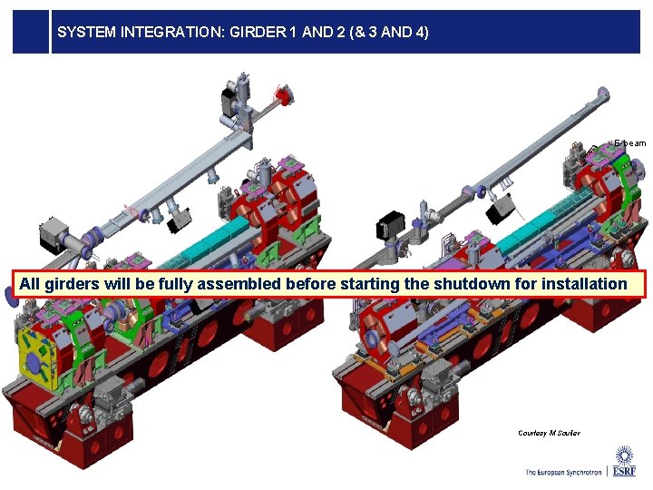
GIRDER DESIGN, THE ORTHOGONAL HEPTAPOD Mass: Magnets: ~ 5 -6 T Magnet supports: ~ 1 T Girders: ~ 3 -3. 5 T Vacuum chamber, pumping etc: ~ 0. 5 T Total weight: ~9 -11 T Quantity : 128 Procurement time scale: 2016 -2017 Technology: Girder material: carbon steel Typical tickness: 30 mm (20 -50) Piece junction: full penetration and continous welding Rails flatness: ± 30 micrometers Page 26 Z X 5900 mm 4 motorized adjustable supports in Z direction 3 manual horizontal jacks (one in X, two in Y) 800 mm 4 th APAC MEETING - 22 -23 OCTOBER 2014 - Cianciosi Filippo Cianciosi
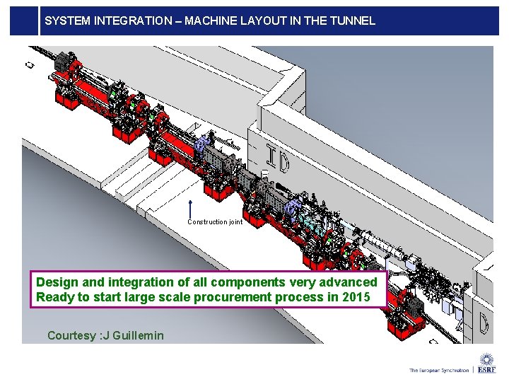
SYSTEM INTEGRATION – MACHINE LAYOUT IN THE TUNNEL Construction joint Design and integration of all components very advanced Ready to start large scale procurement process in 2015 Courtesy : J Guillemin
SYSTEM INTEGRATION: GIRDER 1 AND 2 (& 3 AND 4) E-beam All girders will be fully assembled before starting the shutdown for installation Courtesy M Soulier
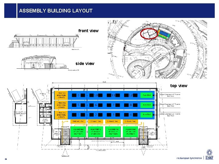
ASSEMBLY BUILDING LAYOUT front view side view top view 29
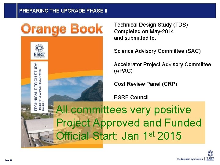
PREPARING THE UPGRADE PHASE II Technical Design Study (TDS) Completed on May-2014 and submitted to: Science Advisory Committee (SAC) Accelerator Project Advisory Committee (APAC) Cost Review Panel (CRP) ESRF Council All committees very positive Project Approved and Funded Official Start: Jan 1 st 2015 Page 30
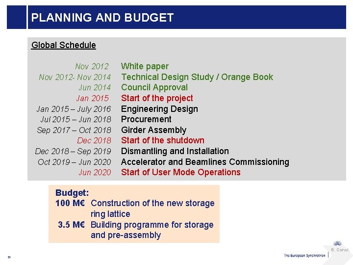
PLANNING AND BUDGET Global Schedule Nov 2012 - Nov 2014 Jun 2014 Jan 2015 – July 2016 Jul 2015 – Jun 2018 Sep 2017 – Oct 2018 Dec 2018 – Sep 2019 Oct 2019 – Jun 2020 White paper Technical Design Study / Orange Book Council Approval Start of the project Engineering Design Procurement Girder Assembly Start of the shutdown Dismantling and Installation Accelerator and Beamlines Commissioning Start of User Mode Operations Budget: 100 M€ Construction of the new storage ring lattice 3. 5 M€ Building programme for storage and pre-assembly 8. Concl. 31
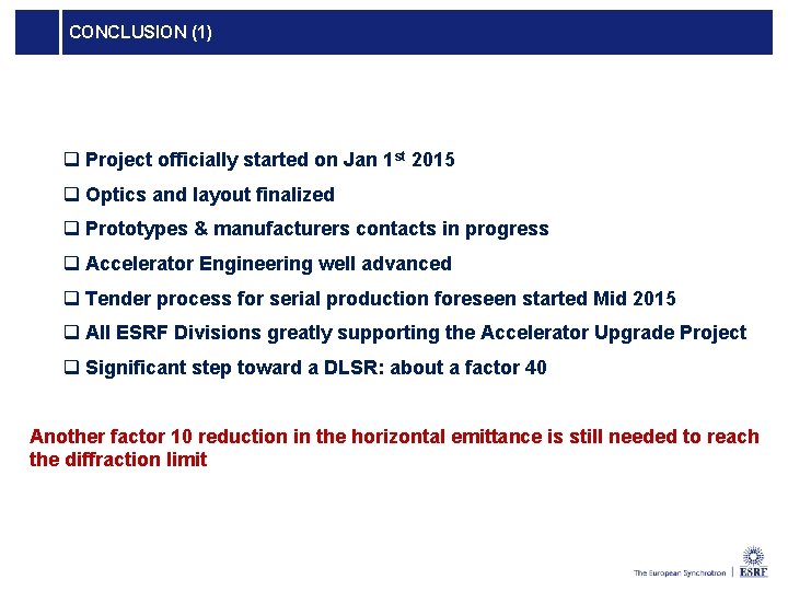
CONCLUSION (1) q Project officially started on Jan 1 st 2015 q Optics and layout finalized q Prototypes & manufacturers contacts in progress q Accelerator Engineering well advanced q Tender process for serial production foreseen started Mid 2015 q All ESRF Divisions greatly supporting the Accelerator Upgrade Project q Significant step toward a DLSR: about a factor 40 Another factor 10 reduction in the horizontal emittance is still needed to reach the diffraction limit
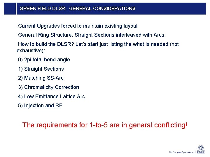
GREEN FIELD DLSR: GENERAL CONSIDERATIONS Current Upgrades forced to maintain existing layout General Ring Structure: Straight Sections interleaved with Arcs How to build the DLSR? Let’s start just listing the what is needed (not exhaustive): 0) 2 pi total bend angle 1) Straight Sections 2) Matching SS-Arc 3) Chromaticity Correction 4) Low Emittance Lattice Arc 5) Injection and RF The requirements for 1 -to-5 are in general conflicting!
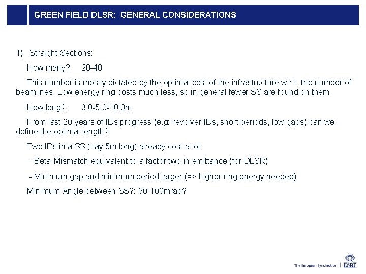
GREEN FIELD DLSR: GENERAL CONSIDERATIONS 1) Straight Sections: How many? : 20 -40 This number is mostly dictated by the optimal cost of the infrastructure w. r. t. the number of beamlines. Low energy ring costs much less, so in general fewer SS are found on them. How long? : 3. 0 -5. 0 -10. 0 m From last 20 years of IDs progress (e. g: revolver IDs, short periods, low gaps) can we define the optimal length? Two IDs in a SS (say 5 m long) already cost a lot: - Beta-Mismatch equivalent to a factor two in emittance (for DLSR) - Minimum gap and minimum period larger (=> higher ring energy needed) Minimum Angle between SS? : 50 -100 mrad?
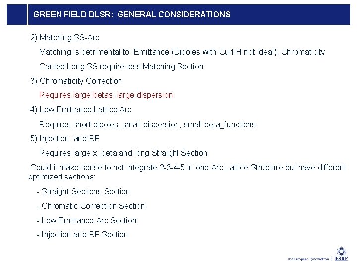
GREEN FIELD DLSR: GENERAL CONSIDERATIONS 2) Matching SS-Arc Matching is detrimental to: Emittance (Dipoles with Curl-H not ideal), Chromaticity Canted Long SS require less Matching Section 3) Chromaticity Correction Requires large betas, large dispersion 4) Low Emittance Lattice Arc Requires short dipoles, small dispersion, small beta_functions 5) Injection and RF Requires large x_beta and long Straight Section Could it make sense to not integrate 2 -3 -4 -5 in one Arc Lattice Structure but have different optimized sections: - Straight Sections Section - Chromatic Correction Section - Low Emittance Arc Section - Injection and RF Section
MANY THANKS FOR YOUR ATTENTION Page 36