Diffraction Dr J P Singh Associate Professor in


")


 and (6) This eqn.")


 Intensity of")
 Intensity of secondary maxima Relative intensity of successive maxima are Intensity of secondary")


 Instead the procedure used for the")


![For N = 2 [for single slit diffraction] Principal Maxima The maximum intensity will](https://slidetodoc.com/presentation_image_h/23de06b5d25fd28bd47390419f45472b/image-66.jpg "For N = 2 [for single slit diffraction] Principal Maxima The maximum intensity will")

 If m = 0 gives")
 minima between two maxima, there must")


 Two objects or two spectral lines are said to be")
 Two objects or two spectral lines are said to be unresolved, if the")
 Two objects or two spectral lines are said to be well resolved, if")


")

- Slides: 93
Diffraction Dr. J P Singh Associate Professor in Physics Post Graduate Govt. College Sector-11 Chandigarh
The deviation of waves from their original direction due to an obstruction in their path is called diffraction.
The phenomenon of diffraction was first observed by an Italian mathematician Grimaldi. A systematic explanation was given by Fresnel on the basis of Huygens’ principle that diffraction is attributed to mutual interference of secondary wavelets from a single wave. The interference phenomenon involve two coherent wave trains. This means that in diffraction phenomenon, interference takes place between secondary wavelets from different part of same wavefront.
Fresnel and Fraunhofer diffraction For mathematical convenience and ease understanding, diffraction is classified in two categories. (1) Fraunhofer diffraction Those in which the source of light and the screen on which the pattern is observed are effectively at infinite distances from the obstacle. This can be done most conveniently using suitable lenses. (2) Fresnel Diffraction Those in which either the source or the screen, or both, are at finite distances from the obstacle.
Huygens' Principle
Let the light originate from a pin hole H, and a certain portion MN of the divergent wave front is allowed to pass the opening. According to the Huygens’ principle, each on the wave front is assumed to be a source of secondary wavelets. The envelope of these at a later instant gives a divergent wave with H as its center and included between the lines HE and HF. This wave as it advances will produce strong illumination in the region EF of the screen. But also a part of each wavelet will travel into the space behind LM and NO, and hence might be expected to produce some light in the regions of geometrical shadow out side of E and F.
Common experience shows that there is actually no illumination on these parts of the screen, expect in the immediate vicinity of E and F. according to Fresnel, this is to be explained by the fact that in the region well beyond the limits of the geometrical shadow the secondary wavelets arrive with these relations such that they interfere destructively and produce practically complete darkness. The secondary wavelets cannot have uniform amplitude in all directions, since tit were so, they would produce an equally strong wave in the backward direction. In the fig. above the envelope on the left side of the screen would represent a wave conversing towards H. Obviously, such a wave
wave conversing towards H. Obviously, such a wave does not exists physically, and hence one assume that the amplitude at the back of secondary wave is zero. (The obliquity factor for Huygens’ secondary wavelets) According to Huygens’ principal the amplitude is given by the oblique factor (1+cosθ), where θ is the angle with the forward direction.
Fresnel’s Half period Zones r₂ r Construction of half period zones on a spherical wave front.
in this figure BCDE represent a spherical wave front on monochromatic light travelling towards right. Every point on this sphere may be thought of as the origin of secondary wavelets, to find the resultant at P, we divide the wave front into zones as following. Around the point O, which is the foot of perpendicular from P, a series of circles are drawn whose distances from O, measured along arc are and are such that each circle is half wavelength further from P. Areas of the zones, i. e. , of the ring between successive circles, are practically equal.
Radius of first half period zone is given by Radius of second half period zone is given by
Radius of various half period zones are The radii are proportional to the square roots of the natural numbers.
To the approximation considered, it is therefore constant and independent of m. A more exact evaluation we would show that area increases very slowly with m. Area = πbλ, which 1. Increases with the increase in the wavelength of light. 2. Increases with the increase in the distance of point P from the wave front. 3. Due to equality of the area of the zones, the amplitude contribution of the secondary wavelets from each zone is expected to be nearly the same.
Distance and obliquity factor Both these increases gradually and regularly as we go to higher zones. Therefore, the amplitude contribution at P decreases gradually as we consider the higher zones. etc be the amplitude contributions at P due to 1 st, 2 nd, 3 ed, . . etc half period zones respectively, then and so on. Thus we can write and so on.
Relative phases of zones The phase difference between consecutive zones is π. So we can consider the amplitude contribution at P due to different zones as alternatively positive and negative. Addition of the amplitudes from half period zones
If m is even the last term is negative Contribution of bracketed terms are almost zero, if m is odd
If m is even m is very large therefore as m tend to infinity Hence resultant amplitude A at P is It shows that the resultant amplitude at a point due to the whole wave front is equal to half of the amplitude due to first half period zone only at that point. Intensity I at a point is proportional to the square of the amplitude A.
Zone Plate This is a special screen designed to block off the light from every other half-period zone. The result is to remove either all positive terms in eq. (1) or all negative terms. In either case the amplitude at P will be increased to many times in value in the above cases. (Positive Zone plate) (Negative Zone plate)
Principle The resultant intensity at a point P is If n very large then Intensity at P is If the even numbered zones are blocked
If the odd numbered zones are blocked The magnitude of amplitude A in both the cases (2) and (3) will almost be the same and the net illumination at the point P (intensity proportional to A²) will be very large. Construction Draw circles on a white paper sheet, with radii proportional to the square root of natural numbers. The odd or even numbered zones are covered with ink. Take photograph of this pattern on a thin glass plate on a reduced scale. This form ZONE PLATE
Theory of zone plate let XY be the section of zone plate perpendicular to the plane of paper. Let O be the luminous object emitting spherical waves of wavelength λ whose effect at point I is required. Y P O u X v I
Let u be the distance of the object O from the zone plate and v is the distance of the screen from the zone plate. PM₁. PM₂, … ( ) are the radii of first , second …etc half period zones. Position of the screen is such that from one zone to the next, there is increase on path difference of λ/2. And so on Similarly points exists on the section XY of ZP below the pole P at exactly the same distances.
Substituting these in (4)
Since, u, v and λ are constants Shows the radii of the various zones for given values of u and v are proportional to the square root of the natural numbers. Area of the nth zone is given by
this is independent of n. hence for a given object O and I, the area of all the zones remain the same. Area diminishes as u and v decreases i. e. plate is approached by the object or image. Working of the zone plate as a lens.
This result is similar to the lens formula From (5) and (6) This eqn. shows that a zone plate has a number of foci which depend on the number of zones as well as wavelength of light used.
Multiple foci of a zone plate the focal length of a zone plate is Thus it behaves like a convex lens, but it has a multiple foci between the zone and point I. this is because the number of half period zones contained in an area depend upon the position of the screen. For n = 1 Say screen at point I obtained using this formula is called the first order focal point (or as primary or principle focal length). Area of each zone is πλf.
Resultant amplitude is given by and the intensity is most intense. Now for n = 2 let the screen is at I₂ such that the distance PI₂= f/2 area of each zone is =πλf/2. Now each zone for I will now contain 2 zones for I₂. Hence for I₂, 1 st and 2 nd zones will be exposed and 3 rd and 4 th zones are blackened. Since and so on therefore
Now for n = 3 let the screen is at I₃ such that the distance PI₃= f/3 area of each zone is =πλf/3. therefore, focal length is Now each zone for I will now contain 3 zones for I₃. Hence for I₃, 1 st , 2 nd and 3 rd zones will be exposed and 4 th, 5 th and 6 th zones are blackened.
Which shows that amplitude at I₃ is greater than i. e. light is focused at I₃ although its intensity is less than that at I. hence this point is also called as focal length. As f₃ = f/3, it is rightly called third order focal length. Similarly it can be shown that Also, the light focuses though intensity or brightness goes on decreases. They are all known as focal lengths. Hence, unlike lens, zone plate has multiple foci.
Focusing action of zone plate When a zone plate is placed in front of source S, on the other side of the axis of the plate, we observe a series of points with their intensities in increasing order as the distance of points from plate increases. Thus the zone plate acts as a conversing lens. However, it is different from a lens, because it is associated with a series of foci and focal lengths.
Phase reversal zone plate Let the even number of half period zones be coated with some trans parent thin film instead of blackening them such that the thin film introduces a path difference of λ/2. then the intensity I will becomes four times because in this case each zone sends waves to the point I in the same phase and resultant amplitude at I is i. e. double that by an ordinary zone plate. Such a zone plate is known as phase reversal zone plate. Comparison betwn convex lens and zone plate At home
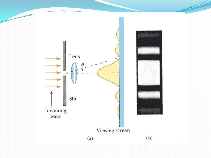
Fraunhofer’s Diffraction at single slit X a C O x dx Y D
Let a monochromatic light of wavelength λ be incident normally upon a narrow slit of width ‘a’ and the diffracted light be focused by a convex lens. The diffraction pattern obtained on the screen consists of central bright band, having alternate dark and bright band of decreasing intensity on either side of bright band. Let the disturbance at any point P on the screen from a unit width of slit at a distance of x from C. Then disturbance at P due to width dx at a distance x from C has
Let the small disturbance dy due to width dx at P is given by Total disturbance at point P due to whole width “a” of slit XY
Multiplying and dividing by in the right side.
Where Then y becomes is the amplitude for θ = 0
Resultant amplitude R at point P is therefore given as Intensity at P is given by Position of central maximum At O the θ = 0 then α becomes
Intensity at O becomes All waves reaches O in phase and the waves are travelling normal to the slit and gives the position of central maximum. Position of minima Intensity in minimum when m = 1, 2, 3, … gives 1 st, 2 nd, 3 rd, …minima respectively
Secondary maxima the direction of mth secondary maxima is given by (1) Intensity of first secondary maxima
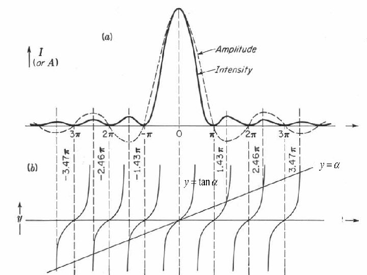
(2) Intensity of secondary maxima Relative intensity of successive maxima are Intensity of secondary maxima falls off rapidly.
Position of secondary maxima This equation can be solved by plotting a graph for y = α and y = tanα
Width of central maximum a O y D
Condition for minimum For the first minima F is he focal length of the lens which is equal to D for plane wave front
Let the first secondary minimum from the center of the principal maximum be y Width is directly proportional to the λ and inversely to the slit width. Effect of slit width If a is large then sinθ is small hence θ is small
Fraunhofer diffraction at a circular aperture f
The rays reaching at P₁ on the screen at a distance y from point P, after diffraction at an angle θ from the extreme ends A and B of the aperture, the path difference is given as Similar to the single slit pattern, if the point P₁ will have minimum, then Because the circular aperture is symmetrical, the resultant pattern is obtained by rotating the screen about the axis OP. The point P will trace out a circular ring of uniform intensity, minimum or maximum depending upon the path difference conditions.
Thus the diffraction pattern due to circular aperture consists of a central bright disc called Airy’s disc surrounded by alternately dark and bright rings called Airy’s rings. The intensity of bright rings goes on decreasing gradually away from O. If lens is very close to aperture and the screen is very large distance then For first minimum Comparing This is the radius of Airy’s disc. In actual practice the radius of Airy’s disc is equal to
Fraunhofer’s Diffraction at double slit a A B b a C θ D O E θ
Both slits can be treated as independent source of light. Let 2α be the phase change between the extreme rays (between A and B)from first slit Let A be the resultant amplitude of all secondary wavelets from one slit AB which is given as Where A₀ = amplitude incident on slit. And α is the half phase between AB.
Path difference between AC is given as Then corresponding phase difference is Let R is the resultant of the two (from A and C) wave of amplitude A each and phase difference 2β and given as
Intensity assuming proportional constant equal to one is given as Resultant intensity depends upon two factors 1. Gives diffraction pattern of individual slits. Gives interference pattern due to diffracted light waves from two slits. gives central maximum direction θ = 0 having alternately minima and secondary maxima of decreasing intensity on either side.
Combination of interference and diffraction for 2 slits diffraction interference Diffraction +interference
Direction of minimum intensity is given by except zero
Direction of bright fringes are obtained by corresponds to zero order, first order, second order…maxima.
Effect of slit width On increasing the slit width a, the central peak becomes sharper, but the fringe spacing remains the same. Hence interference maximum falls within the central diffraction maximum. Effect of distance between the slits. On increasing the distance between the slits b, keeping the slit width constant, the fringes becomes closer together, but the envelope of the pattern remains unchanged. Hence more interference maxima falls within the central envelope.
Missing order in double diffraction pattern Direction for interference maxima And the direction for diffraction minima as If the values of a and b are such that both these equation are simultaneously satisfied for some value of θ, in that case position of interference maxima corresponds to that of diffraction minima. Case (1) if a = b gives
If m =1, 2, 3, …, then n=2, 4, 6, ……, So the second, fourth, sixth, etc, orders of the interference maxima will be missing in the diffraction pattern. Case (2) if 2 a = b Gives If m = 1, 2, 3, …, then n = 3, 6, 9, …etc So the third, sixth, ninth, …etc, orders of the interference maxima will be missing in the diffraction pattern. Case (3) if a + b = a i. e. b = 0 In this case we will have single slit, so all the interference pattern will be missing. In this case, the diffraction pattern observed is similar as single slit.
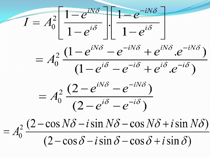
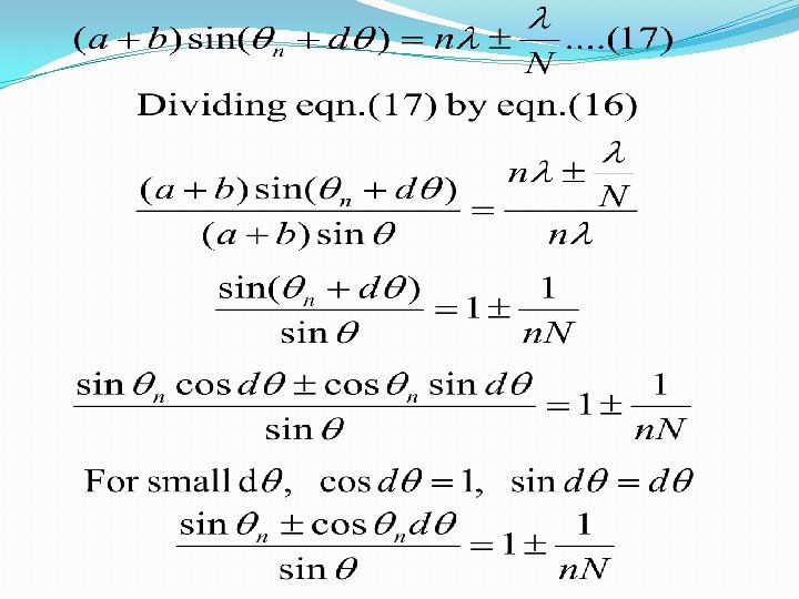
Plane transmission grating (diffraction at N parallel slits) Instead the procedure used for the single and double slits, let us apply the more powerful method of adding the complex amplitudes. For the grating the amplitudes contributed by the individual slits are of equal magnitude. A and the number of slits are N. the phase will change by equal amount from one slit to the next, so the resultant complex amplitude is the sum of the series
Intensity
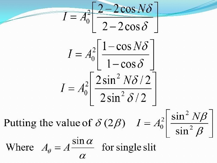
Represent diffraction pattern due to single slit Represent interference pattern due to N slits For N = 1 [for single slit diffraction]
For N = 2 [for single slit diffraction] Principal Maxima The maximum intensity will come for α = 0 and β = 0, i. e. when θ = 0, which gives the position of central maximum. (undefined)
So Because the product of two integer is also an integer So the maximum intensity will be For n = 0, maximum is zero order maximum and for n = ± 1, n ± 2…. etc. are called first order, second order etc of principal maxima respectively.
Secondary minima then from we get (which is minimum) If m = 0 gives principal maxima and m = N also gives principal maxima, the m = 1, 2, 3, …(N-1) gives minima. There is (N-1) minima between two maxima.
Secondary maxima since there are (N – 1) minima between two maxima, there must be (N – 2) between two principal maxima. To find position of these maxima, differentiate eqn. (15) and equate equal to zero. ( N + 1 ²ta n ² / ¹ ²)
Intensity at secondary maxima is given by
From this equation we see that if N is large then the intensity of secondary maxima is less. Since in the grating the number of slits is very large (25000 per inch), the secondary maxima are not visible in grating spectrum. Width of Principal Maxima From Eqn. (16) the condition of nth principal maxima of grating is let maxima on the two sides of the n primary maxima as per positive and negative signs, then
dθ gives the angular half width of nth principal maxima is inversely proportional to the number of slits. If the N (number of slits) is large, then the half angular, width will be small, therefore sharpness increases.
Absent or missing spectra in N slit diffraction pattern Direction of minima for single slit Direction of principal maxima in grating is given as Dividing Case (1) a = b, gives n = 2 m If m = 1, 2, 3, …. . , n = 2, 4, 6, …. Second , forth, sixth, etc orders of spectra are missing. Case (2) b= 2 a If m = 1, 2, 3, …, n = 3, 6, 9, … Third, sixth, ninth, . . etc orders of spectra are missing.
Dispersive power of grating is defined as the change of angle of diffraction with wavelength of monochromatic light that is Differentiating this w. r. t. λ Dispersive power is (i) directly proportional to (ii) inversely proportional to grating element (iii)Inversely proportional to cosine of angle
Grating at oblique incidence A C
Let us now consider a parallel beam of light incident obliquely non the grating surface angle of incident i and the corresponding angle of diffraction as shown in the figure. The path difference between the secondary waves from the corresponding points A and C if the beam diffracted outward is given by For principal maximum
Deviation in the path of incident ray is given by For deviation is minimum ,
Deviation is minimum if angle of incidence is equal to the angle of diffraction. Then the condition of nth order principal maximum then from eqn. (1) Using grating in the minimum deviation position is more advantageous as the definition of of diffracted image considerably improved.
If however, we consider the beam diffracted downwards, the path difference between the points A and C is given by And rest treatment is the same.
Resolving power of an optical instruments Limit of resolution is the smallest separation (linear or angular) between two point objects or images at which they appear to be separated. (i. e. dλ or dθ) Resolving Power is the ability of an optical instrument to resolve the images of two close point objects. Mathematically it is equal to the reciprocal of limit of resolution. Human eye can see two objects as separate only if the angle subtended by them at the eye is greater than one minute, which is the resolving power of eye.
Rayleigh resolution criteria (a) Two objects or two spectral lines are said to be just resolved, if central maximum of diffraction pattern of one object falls on the first central minimum of the diffraction pattern of the other. This condition of resolution is known as Rayleigh criterion. (a)
(b) Two objects or two spectral lines are said to be unresolved, if the distance between the central maximum of diffraction pattern of two objects is less than the distance between the central maximum of diffraction pattern of one and the first secondary minimum of the other or vice versa. (b)
(c) Two objects or two spectral lines are said to be well resolved, if the distance between the central maximum of diffraction pattern of two objects is greater than the distance between the central maximum of diffraction pattern of one and the first secondary minimum of the other or vice versa. (c)
Resolving power of telescope O’ A O O’ O N P D B r P’ Path difference Light from two stars O and O’ making an angle dθ
Path difference between the wavelets emerging from AN is given as D is the diameter of the objective of the lens of telescope, if dθ is small, then If there is path difference of λ then the first minimum due to O’ falls on the central maximum of O, therefore, O and O’ will be resolved. Comparing these two eqn.
Applying Airy’s correction Resolving Power R. P is given as We can see that for reason diameter of the objective should be large.
r is the radius of the central bright f is the focal length of the telescope,
Resolving power of microscope d
Total path difference is given by For Rayleigh’s criterion is to be satisfied Limit of resolution is Resolving power
Resolving power of grating The ability of a diffraction grating to produce the distinct images of two spectral lines of nearly same wavelength is called Resolving power of grating and is measured as the ratio of the wavelength and the least difference in wavelengths between two spectral lines at which they are just resolved. Now the nth principal maximum is given by
If there are N lines on the diffraction grating then there will be (N-1) minima in between the two consecutive principle maxima. Let (θ+dθ) is the angle between first minimum near the nth principal maxima then For Rayleigh’s criterion is to be satisfied Equating these two equations
R. P. increases with N, the number of lines and the order n of diffraction pattern