Digital Microfluidics Control System II Detailed Design P


9 V p-p from signal generator amplified to 120 V p-p between")


- Slides: 39
Digital Microfluidics Control System II Detailed Design P 15610
Agenda ● ● ● ● ● Subsystem Overview Housing Output Board Input Board Signal Generator Amplifier Power Supply Risk Assessment Project Plan
Subsystem Identification
Responsibilities and Subject Matter Experts
Subsystem Specifications
Subsystem: Housing ● Sample Comparison ● Assembly Models ● Access Ports/Cutouts ● Dimensioned Drawings ● Cooling and Grounding ● Bill of Materials ● Test Plan
Sample Comparison
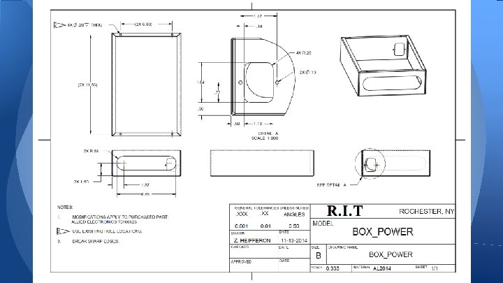
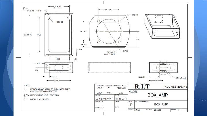
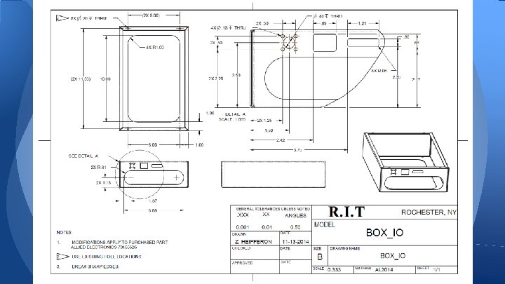
CAD Models
Exploded View Component Mountings; Enclosure-to-Enclosure: Screws with Standoffs Electrical Ports: Wall mounts with screws Fan and Fan Guard: Screws Power Supply: Screws Vent Grommets: Epoxy
Cooling and Grounding ● ● Standard 60 mm CPU fan will be required in order to cool the interior of the housing. Protect the electrical components of the system from overheating. Controlled by system temperature. The fan will be mounted on the back side of the middle enclosure, as shown. The critical components of the grounding system will be a 104 -PR-5 A Miniature Circuit Breaker. This will provide a central overcurrent protection for all system components.
Housing: Bill of Materials
Housing: Test Plan ● Continuity testing will be performed throughout the components of the housing to ensure components are fully grounded. ● The fully assembled system will be run while the fan is operating at its available speed. The internal temperature of the system will be monitored until it reaches steady state, along with the power draw of the fan. a. Ideal Temperature < 60 degrees C b. Ideal Power Draw < 10 Watts ● Housing will be emptied of electrical components, placed on a scale, and weighed. Overall dimensions of the housing will be measured and the total volume will be calculated. a. Ideal Weight < 15 lbs b. Ideal Volume < 2000 in^3 ● Emptied housing will be fully disassembled and reassembled by single person while being timed. a. Ideal Time < 5 minutes Parts necessary ● Digital Multimeter ● Tape measure ● Scale ● Thermocouples
Input/Output Boards -Output Board is identical to the Drop. Bot board -BOM double-checked -PCB layout companies researched -Functionality determined -Input Board has been created -Parts researched and BOM created -PCB to be created -Functionality confirmed in simulation
Output Board: BOM
Output Board: PCB layout
Output Board: PCB layout
Output Board: PCB layout
Output Board: Functionality ● Takes amplified signal from amplifier chooses which pin on DMF chip to apply high voltage ● Consists of: o HV Solid State Relays o Shift Registers (Load pin positions to apply voltage to) o Control Mechanism (ATMEGA)
Output Board: Functionality ATMEGA Shift Register 40 HV Relays Shift Register Off Board DMF Chip
Input Board: BOM
Input Board: Functionality
Input Board: Functionality 1 p. F: steady state voltage of 29 m. V 200 p. F: steady state voltage of 5. 00 V Rise time: <10 ms
Input Board: Functionality 60 p. F: steady state voltage of 1. 693 V 61 p. F: steady state voltage of 1. 720 V Granularity: 27 m. V/p. F or: 5. 5 qlevel/p. F
Input Board: Functionality -Total simulated current draw: <25 m. A -Noise: input filter to buffer limits frequency generator noise -Large capacitive loading: Zener diode limits output (below) -Output noise: two-stage low-pass filter
Input Board: Previous Data -Absolute values of measured capacitances ranged from 30 p. F to 170 p. F -Capacitance changes over time in the minutes -Capacitance differences sub-1 p. F Graphs from Dr. Michael Schertzer “Automated detection of particle concentration and chemical reactions in EWOD devices”
Signal Generator / Amplifier - Signal Generator Board is identical to Drop. Bots - BOM is updated to current supplier - PCB is to be created - Functionality is to be determined Amplifier - BOM is updated - Functionality confirmed with simulations assuming low capacitive load and high resistance
Signal Generator BOM
Signal Generator: PCB Layout
Signal Generator: PCB Layout
Amplifier BOM
Amplifier Functionality -(+)9 V p-p from signal generator amplified to 120 V p-p between ~100 - 100 k. Hz
Amplifier Functionality -Simulated with a 600 u. H Resonant Converter Transformer
Power Supplies - Cosel +/- 15 V DC @ 1. 7 A - Cosel +5 V DC @ 2 A
Risk Assessment
Project Plan
Questions?