Detail and Assembly Drawing Engineering drawing is the

Detail and Assembly Drawing ØEngineering drawing is the language of Engineers. ØIt is a powerful medium of communication between professionals. ØFor manufacturing any object detail as well as assembly drawing need to be drawn. ØIts knowledge is therefore is of utmost importance.

Detail Drawing

Wooden Joints and its types v The joints which assemble two or more wooden members are called wooden joints. v Types of Wooden Joints 1. Corner halving Joint 2. Cross halving joint 3. Tee halving joint 4. Mortice and Tenon joint 5. Open mortice and tenon joint 6. Closed mortice and Tenon joint 7. Tee Bridle joint 8. Dovetail joint 9. Cogged design

Cross Halving Joint

Tee Halving Joint

Mortice and Tenon Joint

Open mortice and Tenon joint

Dovetail Joint

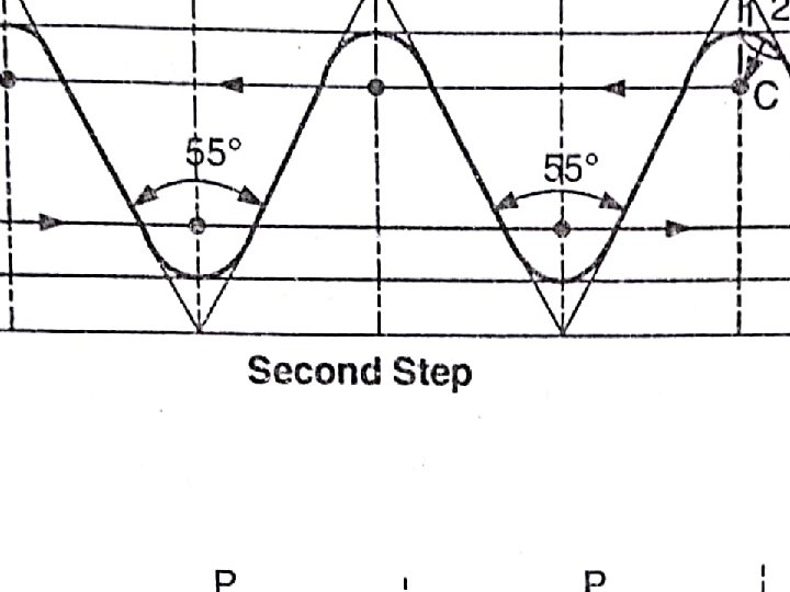
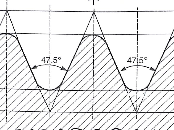
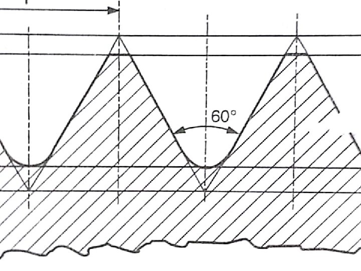
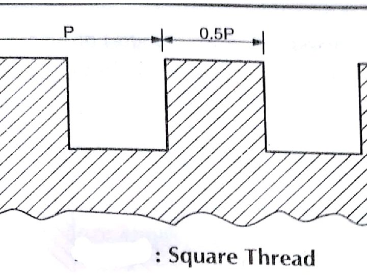
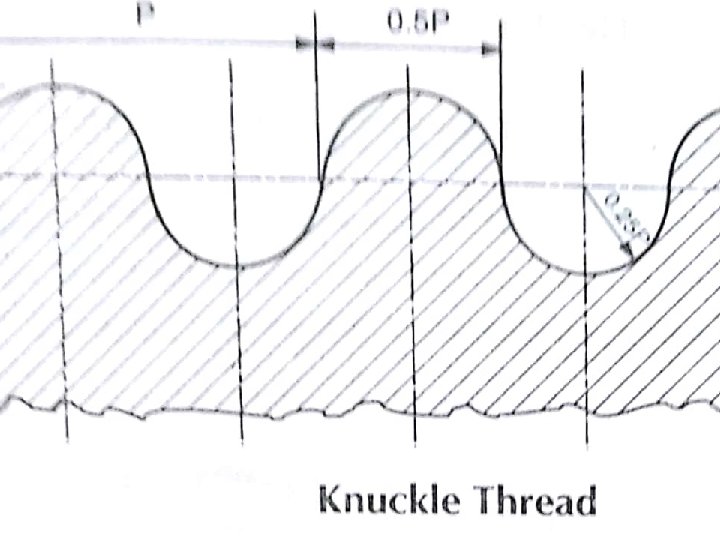
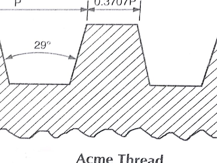
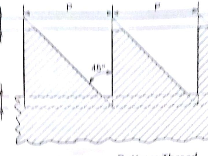
Screw Threads ØA screw thread is formed by cutting a helical groove on a cylindrical surface. ØThis threaded cylindrical surface is called screw. ØThe screws are used to join two parts temporarily. Ø Screw threads are found on nuts, bolts , screws, set screws, studs etc.

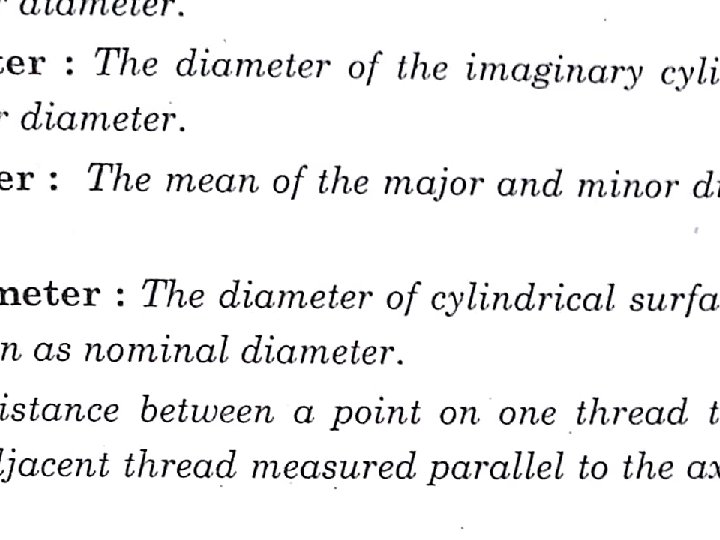
Nomenclature of Screw Threads

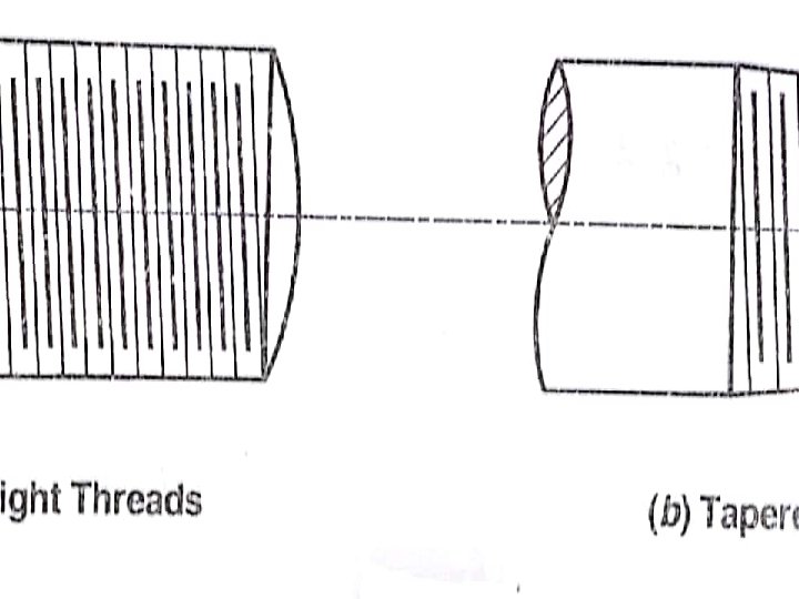

Comparison Left Hand Thread Right Hand Thread

Couplings Ø Shafts are generally available in 6 to 7 meter length. Ø For power transmission at longer distance longer shafts are required. Ø Length of shafts increased by joining two or more shafts. Ø Couplings are used to join two or more shafts. Ø Couplings transmits motion or power from one shaft to another.

Types of Couplings Shafts couplings are broadly divided into two main groups: Ø Rigid Coupling Ø Flexible coupling • Rigid Couplings connect the shaft in perfect axial alignment such as Flange Coupling, Muff Coupling etc. • Flexible Couplings connect the shafts which are not in perfect axial alignment such as Universal Coupling, Pin type flexible coupling etc.

Muff Coupling or box Coupling • It consists of a hollow cast iron cylinder called muff. • The internal diameter of the hollow cast iron cylinder is equal to the external diameter of two shafts to be connected. • There are key –ways in the two shafts at the ends and there is a key way in the hollow portion of the muff or box. • In the key-ways, a gib head key is inserted. • The key is taper for easy extraction of the key. • The taper in the key is 1: 100.
 Ø In ordinary couplings, the bolt heads ad nuts")
Flange coupling ( Protected type) Ø In ordinary couplings, the bolt heads ad nuts are projected beyond the flanges which are liable to cause injuries to material, men and machines around them. ØTo avoid this, protected type flange coupling is used. ØIt consists of two flanges made of cast iron and two shafts made of mild steel.

Half Lap Muff Coupling ØIn half lap muff Coupling, the ends of the shafts are made to overlap each other for a short length. ØThe taper in the overlaps at the ends prevents the shafts from separating, if pulled in opposite direction. ØA hollow saddle key is used to connect the muff and the shafts. ØOnly one box is used to connect the two shafts together. ØThe taper in key is 1: 100. ØThe key prevents the relative rotation between the two shafts and the muff.
")
Flanged Coupling (Non Protected type)

Flexible Coupling ØIn this Coupling, the motion or power is transmitted from one shaft to the other shaft with the help of driving pins rigidly bolted to one flange and loosely fitted to the corresponding holes in the other flange. ØFlexible elements such as rubber washers or leather washers are used around the driving pins for preventing vibrations. ØThe flexible coupling are used to minimize starting shocks.
- Slides: 31