Digital Halftoning What is Digital halftoning History Goals


 • Photomechanical halftoning process was introduced by Talbot in 1852.")

 • In 1882 the German patented a halftone process in England.")

 • Digital halftoning algorithms first appeared in the early 70 s")


 Gray-scale image. (b) halftone image (using clustered dither mask).")


 may be reduced to the")


 • Photo printers – Dot size is fixed – Dot")
 • AM-FM – Dot size and dot frequency varies •")

")

 •")


")


 Halftone, 4 -color print “Moiré pattern” and “Rosette pattern” disappear")


 • Representation of Detail –")

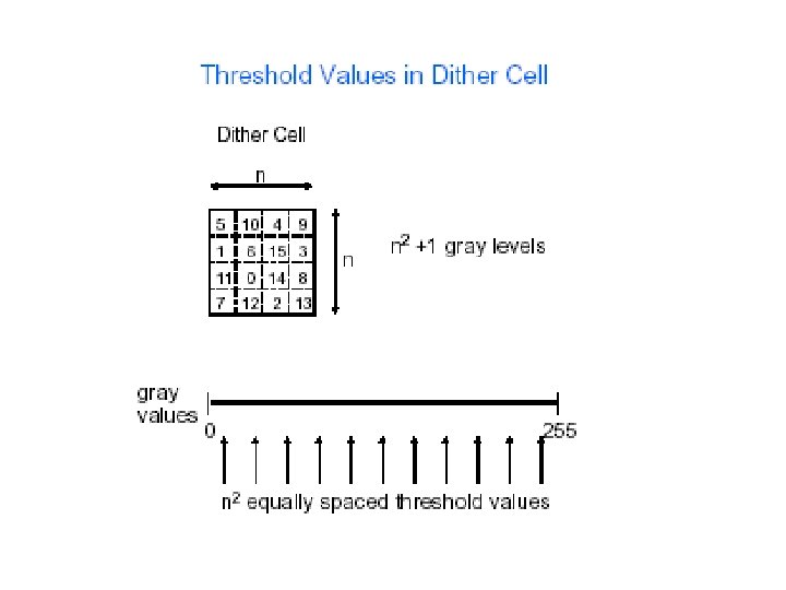
 Halftone cell The fractional area covered by")
: each pixel value is")
 • • The Average Dithering is a basic two-level algorithm for")


 T( i, j ) Fig 3 Dither mask if threshold")


 • For dispersed dot textures, thresholds that are")


 should be placed in the mask as")


- Slides: 83
Digital Halftoning • • What is Digital halftoning History Goals of halftoning Methods of halftoning
1. 1 What is digital halftoning? • Digital halftoning is the process of rendering a continuoustone image with a device that is capable of generating only two or a few levels of gray at each point on the device output surface. • The perception of additional levels of gray depends on a local average of the binary or multilevel texture. • Detail is rendered by local modulation of the texture. Different dot patterns for different levels of gray.
• Halftone is the reprographic technique that simulates continuous tone imagery through the use of dots, varying either in size or in spacing. 'Halftone' can also be used to refer specifically to the image that is produced by this process. • Where continuous tone imagery (film photography, for example) contains an infinite range of colors or greys, the halftone process reduces visual reproductions to a binary image that is printed with only one color of ink. This binary reproduction relies on a basic optical illusion—that these tiny halftone dots are blended into smooth tones by the human eye. • (At a microscopic level, developed black and white photographic film also consists of only two colors, and not an infinite range of continuous tones. For details, see film grain. Next slide) • Just as color photography evolved with the addition of filters and film layers, color printing is made possible by repeating the halftone process for each subtractive color—most commonly using what is called the 'CMYK color model. ' The semi-opaque property of ink allows halftone dots of different colors to create another optical effect —full-color imagery.
Photomicrograph of grain of different photographic plates
Left: Halftone dots. Right: How the human eye would see this sort of arrangement from a sufficient distance.
History • Fundamental concepts have been used for centuries in weaving (by varying the no. of black threads) and engraving (thickness/frequency of the engraved lines)
History (cont. ) • Photomechanical halftoning process was introduced by Talbot in 1852.
The first printed photo using a halftone, December 2, 1873.
History (cont. ) • In 1882 the German patented a halftone process in England. His invention was based on the previous ideas of Berchtold and Swan. He used single lined screens which were turned during exposure to produce cross-lined effects. He was the first to achieve any commercial success with relief halftones. • Shortly afterwards, Ives, this time in collaboration with Louis and Max Levy, improved the process further with the invention and commercial production of quality cross-lined screens. • The relief halftone process proved almost immediately to be a success. The use of halftone blocks in popular journals became regular during the early 1890 s http: //en. wikipedia. org/wiki/Halftone
Three examples of color halftoning with CMYK separations. From left to right: The cyan separation, the magenta separation, the yellow separation, the black separation, the combined halftone pattern and finally how the human eye would observe the combined halftone pattern from a sufficient distance.
History (cont. ) • Digital halftoning algorithms first appeared in the early 70 s as computer graphics displays and hardcopy devices became more widely available. Bayer - 1972 Floyd-Steinberg - 1976
• IBM J. RES. & DEV. VOL. 47 NO. 1 JANUARY 2003
The mathematics of Halftoning - paper The problem of halftoning in digital printing has provided a splendid new example of a mathematical opportunity in modern technology. Digital halftoning is the technique used to display an image with a few immiscible colors discretely applied to paper. At any point on the paper there is only one color dot ( no mixing/superimposition of colors). This problem involves various fields of science such as the physics of light, the biology of the human visual system, and the mathematics of analog to digital conversion. Digital halftoning can be considered as a huge optimization problem, but we shall see that by sacrificing optimality one can construct efficient algorithms which achieve very satisfactory results. Halftoning is above all an art, yet mathematics, particularly theory of dynamical systems, helps to improve this art, while the art suggests a rich collection of mathematical problems and insights. • Specifically, we address the question of how full-color images should be imitated by printers which print at positions on a lattice with colors limited to a few available choices.
Purists use the term pixels for screens and instead use pels for printing, but we shall stick to pixels. Pixel colors are for the colors of inks or toners. In some printers the choice of pixel colors can be augmented by superposition of these substances, but this is not allowed in highlight printers. The two images of Brian Wu (see Figure 1) illustrate halftoning for gray scale: Figure 1(b) is a coarsegrain halftone image of the fine-grain image in Figure 1(a), which is approximately a full gray-scale image.
Fig 1 (a) Gray-scale image. (b) halftone image (using clustered dither mask).
Color Half toning • In color half toning one uses R, G, B pens which print /produce dots of full color (255) of each or leave blank ( i. e. r =g=b=0). These dots are equally spaced with varying sizes. • Halftoning is for approximate reproducing a given color patch/area and not for a color point.
• • • In color half toning, one uses R, G, B pens which print /produce dots of full color (255) of each or leave blank ( i. e. r =g=b=0). These dots are equally spaced with varying sizes. Halftoning is for approximate reproducing a given color patch/area and not for a color point. The human eye perceives diffusion as a mixture of the colors within it. Reducing the color depth of an image can often have significant visual sideeffects. If the original image is a photograph, it is likely to have thousands, or even millions of distinct colors. The process of constraining the available colors to a specific color palette effectively throws away a certain amount of color information. An illustration of dithering. Red and blue are the only colors used, but as the pixels become smaller, the patch appears violet (R+B).
• Colors and gamuts • Perception of color is modelled as a vector addition in color space. Standard ink and toner colors are cyan (C), magenta (M), yellow (Y), and black (K). The letters in parentheses represent color vectors. Added to this set is white (W), taken for the color of paper. The primary colors for light are red (R), green (G), and blue (B). In color space we have the following relations: W = R + G + B M = W - G = R + B C = W - R = G + B Y = W - B = R + G Since inks and toners act as light absorbers, only blue light is reflected from a combination of magenta and cyan on white paper. B = M + C Similarly, only red light is reflected from magenta and yellow, and green from cyan and yellow. The eye averages received light over areas consisting of many pixels.
When all eight colors C, M, Y, R, G, B, K, and W are available to a printer and arranged in the cube, as in Figure 2, the Cartesian product structure of the cube allows for significant mathematical simplification in printing, as follows: 1. Each component of a color vector along the C, M, Y axes is treated separately with W in the same way one would deal with a black and white image. The page is overprinted three times, one for each pixel color, and possibly a fourth time in order to print as much K as possible (black ink or toner is cheaper, and K, W render better grays than C, M, Y, W). 2. When overprinting the sheet multiple times, one must take care of interference (Moire´) patterns due to misalignment in the superposition of colors, a phenomenon which is now well understood. Actually, the eight color vectors form the vertices of a six-sided figure which is far from cubic in any perceptual color space such as the one given by the CIE colorimetric system. Furthermore, constraints such as the impossibility of superimposing inks to get R, G, or B, or the addition of other shades to augment printer gamuts, such as “light magenta” and “light cyan, ” also lead to significant departures from the cube.
• For example, an original image (Figure 1) may be reduced to the 216 -color palette. • If the original pixel colors are simply translated into the closest available color from the palette, no halftoning occurs (Figure 2). • Typically, this approach results in flat areas and a loss of detail, and may produce patches of color that are significantly different from the original. Shaded or gradient areas may appear as color bands, which may be distracting. Figure 1 Figure 2
• The application of halftoning can help to minimize such visual artifacts, and usually results in a better representation of the original (Figure 3). Halftoning helps to reduce color banding and flatness. Figure 3
Need for Digital Image Halftoning • Examples of reduced grayscale/color resolution – Laser and inkjet printers – Facsimile machines – Low-cost liquid crystal displays • Halftoning is wordlength reduction for images – Grayscale: 8 -bit to 1 -bit (binary) – Color displays: 24 -bit RGB to 8 -bit RGB – Color printers: 24 -bit RGB to CMY (each color binarized) • Halftoning tries to reproduce full range of gray/ color while preserving quality & spatial resolution – Screening methods are pixel-parallel, fast, and simple – Error diffusion gives better results on some media
Applications • Display hardware, including early computer video adapters and many modern LCDs used in mobile phones and inexpensive digital cameras, are only capable of showing a smaller color range than more advanced displays. One common application of dithering is to more accurately display graphics containing a greater range of colors than the hardware is capable of showing. • For example, dithering might be used in order to display a photographic image containing millions of colors on video hardware that is only capable of showing 256 colors at a time. The 256 available colors would be used to generate a dithered approximation of the original image. Without dithering, the colors in the original image might be simply be "rounded off" to the closest available color, resulting in a new image that is a poor representation of the original. Dithering takes advantage of the human eye's tendency to "mix" two colors in close proximity to one another. ex: light colors can be created by adding white dots in between the colors.
• But even when the total number of available colors in the display hardware is high enough when rendering full color digital photographs, as those 15 - and 16 -bit RGB Hicolor 32, 768/65, 536 color modes, banding can be evident to the eye, especially in large areas of smooth shade transitions (although the original image file has no banding at all). Dithering the 32 or 64 RGB levels will result in a pretty good "pseudo truecolor" display approximation, which the eye cannot resolve as grainy. • Another useful application of dithering is for situations in which the graphic file format is the limiting factor. In particular, the commonlyused GIF format is restricted to the use of 256 or fewer colors in many graphics editing software. Images in other file formats, such as PNG, may also have such a restriction imposed on them for the sake of a reduction in file size. Images such as these have a fixed color palette defining all the colors that the image may use. For such situations, graphical editing software may be responsible for dithering images prior to saving them in such restrictive formats.
Traditional screening Modulation Strategies • The most common method of creating screens—amplitude modulation—produces a regular grid of dots that vary in size. • The other method of creating screens—frequency modulation—is used in a process named “Stochastic screening”. • Amplitude modulation - dot size varies, dot spacing is fixed. • Frequency modulation - dot spacing varies, dot size is fixed.
Conventional AM halftoning • Indigo’s “Sequin” halftoning – Dot frequency is fixed – Dot size varies to represent tone • Disadvantages – Rosette patterns : different magnitudes in different directions – Tone jumps – Detail rendition suffers – Scan quality suffers Rosette pattern When preparing color separations for printing, the screen angles are rotated for each process color ink. A symmetrical (but nonobjectionable) "rosette" dot pattern can result, which the eye can merge into smooth color gradations. However, incorrect screening angles or the shifting of the paper during printing can result in objectionable patterns; see "moiré' patterns".
FM halftoning ( “blue-noise”) • Photo printers – Dot size is fixed – Dot frequency varies • Advantages – Does not cause Moiré – Rosette patterns eliminated – Tone jumps not abrupt – Better detail rendition – Better quality at consumer grade scan resolutions • Disadvantages – Depends heavily on fidelity of isolated dot reproduction dot dropout and banding in highlights clumping in the midtones results in grain
AM-FM halftoning ( “green-noise”) • AM-FM – Dot size and dot frequency varies • Advantages – Promise of the “best of both worlds” • Disadvantages – Design depends on particular dot formation characteristics – Difficult design problem highlights midtones
AM FM FM AM AM-FM
AM & FM Halftone AM FM (looks better)
Multiple screens and color halftoning • When different screens are combined, a number of distracting visual effects can occur, including the edges being overly emphasized, as well as a moiré pattern. This problem can be reduced by rotating the screens in relation to each other. This screen angle is another common measurement used in printing, measured in degrees clockwise from a line running to the left (9 o'clock is zero degrees). • Halftoning is also commonly used for printing color pictures. The general idea is the same, by varying the density of the four primary printing colors, cyan, magenta, yellow and black (abbreviation CMYK), any particular shade can be reproduced. In this case there is an additional problem that can occur. In the simple case, one could create a halftone using the same techniques used for printing shades of grey, but in this case the different printing colors have to remain physically close to each other to fool the eye into thinking they are a single color. To do this the industry has standardized on a set of known angles, which result in the dots forming into small circles or rosettes. • The dots cannot easily be seen by the naked eye, but can be discerned through a microscope or a magnifying glass
COLOR PRINT • Three secondary colors • And Black • RED (R, MY) • GREEN (G, CY) • BLUE (B, CM) • BLACK (K, CMY)
Resolution of halftone screens • The resolution of a halftone screen is measured in lines per inch (lpi). This is the number of lines of dots in one inch, measured parallel with the screen's angle. Known as the screen ruling, the resolution of a screen is written either with the suffix lpi or a hash mark. E. g. 150 lpi or 150#. • The higher the pixel resolution of a source file, the greater the detail that can be reproduced. However, such increase also requires a corresponding increase in screen ruling or the output will suffer from posterization. Therefore file resolution is matched to the output resolution. Typical Halftone Resolutions Screen Printing Laser Printer (300 dpi) Laser Printer (600 dpi) 45 -65 lpi 85 -105 lpi Offset Press (newsprint paper) 85 lpi Offset Press (coated paper) 85 -185 lpi
Posterization • Posterization of an image occurs when a region of an image with a continuous gradation of tone is replaced with several regions of fewer tones, resulting in an abrupt change from one to another. This creates an effect somewhat similar to that of a simple usual graphic poster.
AM HALFTONE same angle for C, M, Y & K
Conventional Color Halftoning Same raster angle Error in position cause color shift (translation error)
Conventional Color Halftoning Same raster angle Error in raster angle can cause Moiré ( rotation error)
AM HALFTONE different angles for C, M, Y and K 15, 75, 0 and 45 degrees
Conventional Color Halftoning Different raster angle, 0, 15, 75 and 45 degrees AM different angles Rosette patterns FM
ROSETTE PATTERN
ROSETTE PATTERN
FM (Stochastic) Halftone, 4 -color print “Moiré pattern” and “Rosette pattern” disappear
COLOR PRINT Original
COLOR PRINT AM
COLOR PRINT FM
Architectures for halftoning algorithms • There are three basic architectures for halftoning algorithms. – Dithering – point-to-point operation. – Error diffusion – neighborhood processing. – Search-based methods – usually are iterative. » Ex: Direct Binary Search (DBS)
The Two Fundamental Goals of Digital Halftoning • Representation of Tone – smooth, homogeneous texture. – free from visible structure or contouring. Diamond dot screen Bayer screen Error diffusion Direct Binary Search (DBS)
The Two Fundamental Goals of Digital Halftoning (cont. ) • Representation of Detail – sharp, distinct, and good contrast in rendering of fine structure in image. – good rendering of lines, edges, and type characters. – freedom from Moire due to interference between halftone algorithm and image content Diamond dot screen Error diffusion DBS
Basic Structure of Dithering Algorithm The threshold matrix is periodically tiled over the entire continuous-tone image. If threshold is satisfied, put a dot (black). 2 x 2 threshold matrix (i. e. four thresholds) renders five levels of gray, which is shown below. The locations of the dots correspond to the respective locations of the threshold matrix values.
HALFTONE CELL Pixel (/a number of pixels) Halftone cell The fractional area covered by the ink corresponds to the value of the pixel (or the area)
Dithering algorithms Dithering methods include: • Thresholding (also average dithering): each pixel value is compared against a fixed threshold. This may be the simplest dithering algorithm there is, but it results in immense loss of detail and contouring. • Random dithering was the first attempt (at least as early as 1951) to remedy the drawbacks of thresholding. Each pixel value is compared against a random threshold, resulting in a noisy image. Although this method doesn't generate patterned artifacts, the noise tends to swamp the detail of the image • Ordered dithering: dithers using a fixed pattern. For every pixel in the image the value of the pattern at the corresponding location is used as a threshold. Different patterns can generate completely different dithering effects.
Thresholding (average dithering) • • The Average Dithering is a basic two-level algorithm for halftone image. It consists in choosing a certain constant gray level, in particular the average value of image pixels, and using it as a global threshold in deciding whether a pixel should be quantized to 0 or to 1. All pixels whose intensity level lies above the average value (the threshold) are quantized to 1; all others get a value of 0. This method is simple to implement but it has a disadvantage: quantization contouring is quite perceptible.
Original Threshold Dithering
Random dithering • It is not really acceptable as a production method, but it is very simple to describe and implement. • For each value in the image, simply generate a random number 1. . 256; if it is greater than the image value at that point, plot the point white, otherwise plot it black. That's it. • This generates a picture with a lot of "white noise", which looks like TV picture "snow". Though the image produced is very inaccurate and noisy, it is free from "artifacts" which are phenomena produced by digital signal processing. • Many techniques exist for the reduction of digital artifacts like these, most of which involve using a little randomness to 'perturb' a regular algorithm a little. Random dither obviously takes this to extreme. • While random dither adds a lot of high-frequency noise to a picture, it is useful in reproducing very low-frequency images where the absence of artifacts is more important than noise. • For example, a whole screen containing a gradient of all levels from black to white would actually look best with a random dither. In this case, ordered dithering would produce diagonal patterns, and error dispersion would produce clustering.
Original Random dithering
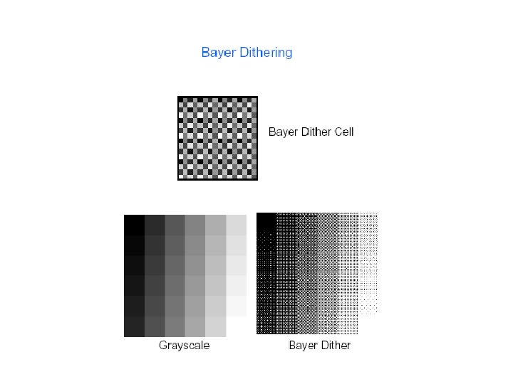
Ordered dithering • Halftone dithering looks similar to halftone screening in newspapers. This is a form of clustered dithering, in that dots tend to cluster together. This can help hide the adverse effects of blurry pixels found on some older output devices. – Two approaches » Dispersed: turn on the pixel individually » Clustered: group pixels to clusters • Bayer dithering produces a cross-hatch pattern. This is a form of dispersed dithering. Because the dots don't cluster, the result looks much less grainy
Dithering is based on a completely local determination which is both simple and fast. We first consider the easier case of black and white (BW) printing, for which the color dimension is 1. Furthermore, we assume that the index dimension is 2. A dithering mask (mask for short) is specified by an n x m matrix M of threshold coefficients M(i, j). The numbers M(i, j) range over the unit interval in a uniform fashion. The image to be halftoned is a h x v matrix T of input gray levels T(i, j), also numbers in the unit interval. Typically, n and m are much smaller than either v or h. i. e. the dither mask is much smaller than the given image. The output image ( halftone image) is given by an h x v zero-one matrix φ [(i, j)], which controls the printing of black as follows: At pixel location (i, j), black is printed if and only if φ(i, j) = 1. The matrix φ(i, j) is defined by φ(i, j) = 1 if T(i, j) > M ( i mod n, j mod m ) --- print black 0 therwise See fig 3
M( i, j ) T( i, j ) Fig 3 Dither mask if threshold exceeds, print black φ( i, j ) Note: The -45 degrees white diagonal in T(i, j) is approximately retained in φ( i, j )
• The problem of dithering is to arrange the numbers n x m in matrix M(i, j) in the mask, so that good image quality results. • This can be quite printer-dependent, at least when it comes to fine tuning. • The more thresholds in the mask, the more continuity in the gray spectrum and the smoother the picture. • A commonly used upper limit to the number of gray levels is 256. Masks are constructed so that constant gray images look good, the idea being that natural images, which are nearly constant small areas, will then also look good. • There is a price to be paid for the instant decision-making ability of a mask: Namely, it is always possible to construct improbable images on which it will fail badly. • However, this does not happen for the usual pictures for which masks are designed.
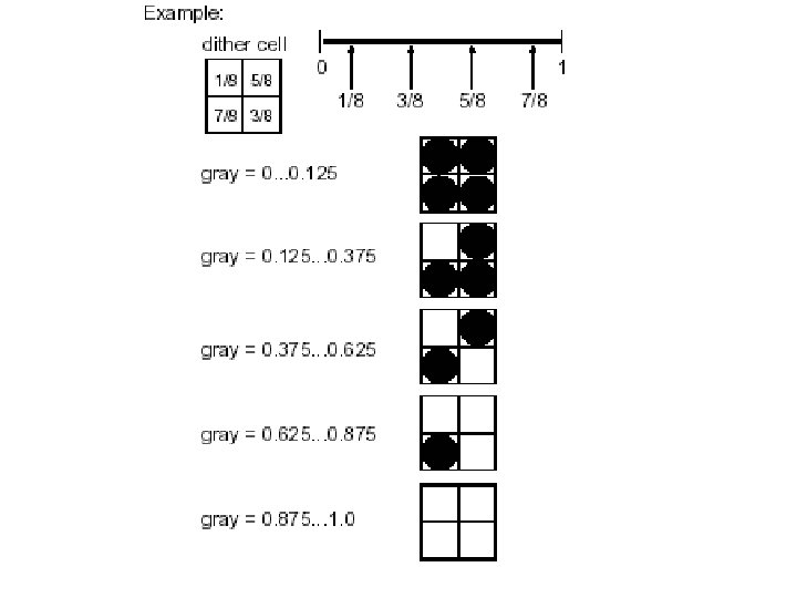
Selection of Threshold Values • For an Mx. N halftone cell, can print 0, 1, 2, …, MN dots, yielding average absorptances 0, 1/MN, 2/MN, …, 1, respectively. • As the input gray level increases, each time a threshold is exceeded, we add a new dot, thereby increasing the rendered absorptance by 1/MN. • It follows that the threshold levels should be uniformly spaced over the range of gray values of the input image.
How Tone is Rendered • If we threshold the screen against a constant gray value, we obtain the binary texture used to represent that constant level of absorptance. This is the halftone image for the original continuous tone image. Is this a good mask? No, because we see diagonal lines in the uniform region (original).
Dot Profile Function • The family of binary textures used to render each level of constant tone is called the dot profile function. • There is a one-to-one relationship between the dot profile and the screen. Dot Profile patterns correspond to the respective locations of the values in the given threshold matrix. Threshold Matrix 6 13 14 7 12 2 3 15 11 1 4 16 5 10 9 8
Selecting Patterns • Avoid Symmetry • At each level we select all the pixels on the previous level and turn on one pixel more • Black circles should be as close as possible to the center of the pattern.
Half Tone and Dithering Half tone Pattern is a rectangular pixel regions used to approximate the halftone production 2 x 2 Halftone Pattern Arrangement possibilities for one dot assignment
HALFTONING If pattern is like this Clustered If pattern is like this Dispersed
Rendering of Detail - Partial Dotting Values represent Average gray levels Cluster dither mask
Partial Dotting - Example
Spatial Arrangement of Thresholds (cont. ) • For dispersed dot textures, thresholds that are close in value are located far apart in the threshold matrix. Dispersed dither mask Rule: If image gray value is greater than the corresponding mask value, put/print a dot (black).
Detail Rendition with Dispersed Dot Screens • Compute the halftone image in the example given below to show detail is rendered with a dispersed dot screen. Dispersed dither mask
THRESHOLD MATRIX Example: Line 1 2 5 6 9 10 13 14 3 7 11 15 4 8 12 16 Thresholds are arranged in lines.
THRESHOLD MATRIX Example: Spiral 1 12 11 10 2 13 16 9 3 14 15 8 4 5 6 7 Thresholds are arranged in spiral manner.
THRESHOLD MATRIX Clustered & Dispersed, 45 degrees 14 5 6 9 19 28 27 24 12 13 4 3 1 2 7 8 21 20 29 30 32 31 26 25 16 10 11 15 17 23 22 18 19 28 27 24 14 5 6 9 21 20 29 30 32 31 26 25 12 13 4 3 1 2 7 8 Clustered 17 23 22 18 16 10 11 15 1 30 8 28 17 9 24 16 5 25 3 32 21 13 19 11 2 29 7 27 18 10 23 15 6 26 4 31 22 14 20 12 1 30 8 28 17 9 24 16 5 25 3 32 21 13 19 11 Dispersed The 4 x 4 submatrices are repeated diagonally (45 degrees).
Clustered vs. Dispersed Dots Attribute Texture Visibility Detail Rendering Stability Clustered Dot High Fair High Dispersed Dot Low Good Low • Note that these assessments are relative. • For example, at sufficiently high resolution, clustered dot textures will also have low visibility and good detail rendition.
One might think that numbers M(i, j) should be placed in the mask as randomly as possible. However, this produces undesirable irregular clusters and other unpleasant defects. To avoid such shortcomings, one tries to place numbers in the mask so that φ(i, j) = 1 will be well dispersed for each gray level. Masks by their nature (dispersed or clustered) impose an increasing gray-level constraint (or stacking constraint); i. e. , if some pixel is printed for a gray level, it is also printed for any darker one (see fig. below). This constraint presents a serious difficulty in designing masks.
• • • Another disturbing feature of an improperly constructed dispersed mask is that periods n and m of the mask dimensions can sometimes be detected. To avoid this, masks are often constructed so that the product n x m is much larger than the number of distinct threshold levels. Particularly popular in this respect are blue noise masks, so called because low frequencies in the power spectrum of the patterns turn out to be attenuated. The most pleasing pattern for gray level 0. 5 is the maximally dispersed checkerboard pattern, but too much regularity in the presence of noise is undesirable, so checkerboard patterns are avoided in most blue noise masks (high frequency). Adler, Thompson, Tresser, and Wu based an invention the aperiodic Thue–Morse sequence 1 in order to tile large mask by two much smaller ones. The memory required for this is considerably less than that for one large mask alone. This gives an alternative (or a complement) to blue noise masks, and can be used in the clustered mask case also.
Thue-Morse sequence • In mathematics and its applications, the Thue-Morse sequence, or Prouhet-Thue-Morse sequence, is a certain binary sequence whose initial segments alternate (in a certain sense). • Bitwise negation • T 0 =0. • T 1 = 01. • T 2 = 0110. • T 3 = 01101001. • T 4 = 011010010110. • T 5 = 011010010110100101101001. • T 6 = 011010010110100101101001 100101101001011010010110. • And so on.
Construction of a 2 -D Thue-Morse pattern • A 2 -D Thue-Morse pattern, where each row and column is a Thue-Morse sequence, can also be formed by a recursive concatenation as described in previous slide. The complement of an array of symbols is concatenated to itself, first in one direction and then the other: 8 th generation 1 st generation (corresponding to : a b. . . ba 3 rd generation 2 nd generation (corresponding to : a b b a. . . baab abba. . . ) 4 th generation
Clustered masks Size of clustered mask should larger than number of gray levels in the given image. Furthermore, there is a tradeoff between the number of gray levels to be rendered and the size of clusters: The bigger the cluster, the more levels the mask can render, but the more noticeable the cluster. Thompson, Tresser, and Wu, using ideas inspired by celestial and statistical mechanics, have addressed this difficulty in patents. The main idea behind the new masks is to start with a large mask consisting of several copies of a small mask with 256 levels.
• There are certain gray levels for which there is an ideal pattern: for example, the checkerboard for the 0. 5 gray level. One attempts to keep these patterns and obtain the intermediate threshold values by interpolation. • This involves a trial-and-error procedure in which one repetitively resets thresholds and judges print quality. • This method is very versatile, and it can be used for a variety of situations: for example, to create several masks for machines whose behavior degrades between maintenances, to adapt a mask to a new printer that has been tuned for another, etc. Other inventions mentioned above concern variations on this theme. Such ideas can also be used for the simpler problem of building dispersed masks.
For standard color dithering, four different masks are used, one for each nonwhite color (including K, which is applied first, since it is usually the cheapest ink). Using the same mask four times is usually avoided because of the possibility of misregistration that causes disturbing Moire´ patterns. In the past, color printing was done with screens that performed like masks (indeed, the word screen is still used in lieu of dithering mask). To minimize Moire´ patterns, the screens for separate colors were set at different angles. For digital printing, there is a technique designing the different masks that is equivalent to the effect of rotating a screen. Humans vision is least sensitive to 45 degrees. For a description of this method. A pending patent by Rao, Thompson, Tresser, and Wu proposes to build what they call semidigital printers: printers intermediate to digital and analog ones, in which each color plane is treated as in the usual digital printing, but the screens/dither masks are rotated as in traditional analog printing.