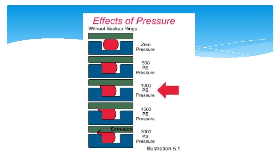
Design of Seals Design of ORing Seals Primary


 Rotary speeds ( not")

 Variety of trade names Copolymer of butadiene and acrylonitrile")
 Excellent resistance to petroleum-based oils and fuels silicone greases")
 Applications Oil resistant applications Low temperature uses Off-road equipment")
 1/32 to 26 inches CS")


 Compression set Thermal")
 Depth of groove Width of groove")
")

")


 = W - H Min. Comp. =")


 Min. Comp.")


- Slides: 80
Design of Seals
Design of O-Ring Seals Primary Source of information
Why O-Rings? Static and dynamic applications Compact Easy to use Simple design rules Easy to install or remove Easy to service Available in many standard sizes, materials
Why O-Rings? Wide range of operating temperatures Wide range of operating pressures Good durability and abrasion resistance Materials for a wide range of chemicals Deterioration is gradual Inexpensive
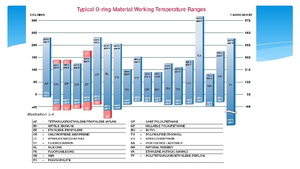
Limitations of O-rings Temperature (Typically -40 and 400 degrees F) Rotary speeds ( not to exceeding 1500 feet per minute) For a 2 inch shaft, it is 3000 rpm Vulnerable to sharp edges
O-Rings
Popular O-ring materials Nitrile (Buna-N) Variety of trade names Copolymer of butadiene and acrylonitrile Most widely used and economical elastomer Temperature Range: -40° to +257°F Hardness (Shore A): 40 to 90
Popular O-ring materials Nitrile (Buna-N) Excellent resistance to petroleum-based oils and fuels silicone greases hydraulic fluids water and alcohol High tensile strength High abrasion resistance
Popular O-ring materials Nitrile (Buna-N) Applications Oil resistant applications Low temperature uses Off-road equipment Automotive, marine, aircraft fuel systems
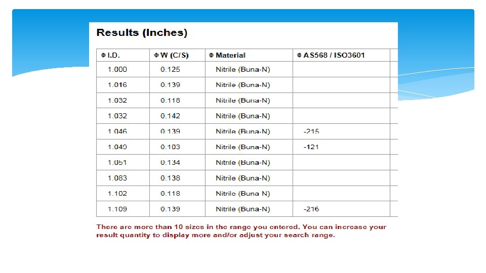
O-Ring Seal Design The O-ring Specifications Size (inside diameter) 1/32 to 26 inches CS (Cross-Section) 1/32 to ¼ inch Rigidity (Hardness) Material
O-ring Standards Standard AS 568 ISO 3601 Example AS 016 -70 N Nitrile O-ring (AS 568 -016 Size 0. 070 CS x 0. 614 ID)
O-ring Search Tools
O-Ring Hardness Measured on Shore-A hardness index Shore 20 A = Rubber Band Shore 40 A = Pencil Eraser Shore 60 A = Car Tire Tread Shore 70 A* = Running Shoe Sole Shore 80 A = Leather Belt Shore 100 A = Shopping Cart Wheel
O-Ring Properties Fluid resistance Hardness Toughness Volume change (swell / shrinkage) Compression set Thermal effects Resilience Deterioration Corrosion Permeability Coefficient of friction Coefficient of thermal expansion Compression set relaxation Tensile strength Elongation Tear resistance / Abrasion resistance
O-ring Seal Design The Gland (Groove + Spacing) Depth of groove Width of groove Diameter of bore and piston Surface finish Tolerances
Static Seals Static Axial Seal (Face Seal)
Static Seals Static Crush Seal
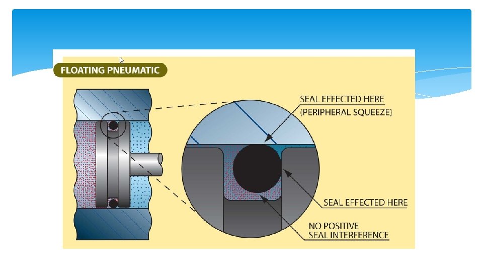
Static Seals Static Radial Seal (Piston Seal)
Dynamic Seals Reciprocating Seals
Dynamic Seals Rotary Seals
Dynamic Seals
General Design Guidelines Stretch should be less than 5% on the O-ring I. D.
Design Guidelines Groove depth must be smaller than the O-ring CS
Design Guidelines O-ring should not completely fill the gland Between 75% and 90% Static seal CS should be compressed from 10% to 40% Dynamic seals should be compressed from 10% to 30%
Design of Axial Seal
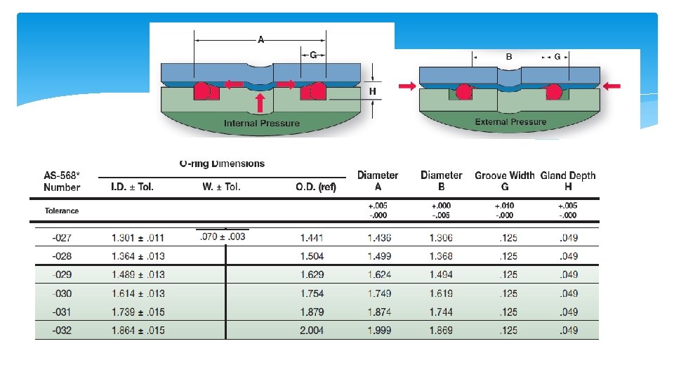
Example Design a groove for a 1. 5 inch diameter Internal pressure O-ring : -029 (ID: 1. 489 +/-. 013) (W: . 07 +/-. 003) Material: Buna-N Hardness: 70 Shore-A A: 1. 624 (-0 , +. 005) G: . 125 (-0, +. 01) H: . 049 (-0, +. 005)
Example Design Checking resulting compression Compression (squeeze) = W - H Min. Comp. = 0. 013 in (18. 5%) Max. Comp. = 0. 024 in (34. 3%)
Radial Seal Radial Static Piston Seal
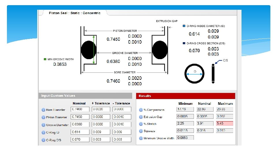
Example Design a groove for a 0. 7 inch diameter piston ring O-ring : -029 (ID: . 614 +/-. 009) (W: . 07 +/-. 003) Material: Buna-N Hardness: 70 Shore-A A: . 746 (-0 , +. 002) B: . 745 (-. 001, + 0) C: . 638 (-. 001, + 0)
Example Design Checking compression Comp = W – 0. 5(A - C) Min. Comp. = 17. 1% Max. Comp. = 26. 0% Also check Extrusion gap Stretch
Radial Static Rod Seal
Static Crush Seal
Static Crush Seal
Dynamic Seals
Reciprocating Motion
Alternatives to O-Rings U-cup Seals O-rings have a tendency to roll and move in reciprocating motions U-cups create more sealing as the pressure increases U-cups require less precision for the associated hardware
Alternatives to O-Rings U-cup Seals
Typical Applications
Buffer Seal Buffer seals are one-way seals that protect rod seals from pressure spikes yet allow fluid (lubricant) to reach the main seal
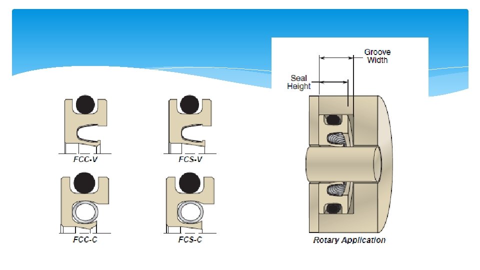
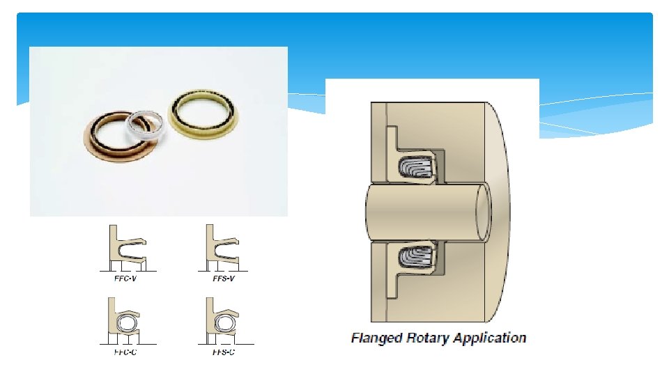
Rotary Seals
Due to centrifugal force and Gough-Joule effect rotary O-rings are only installed in the housing not on the shaft
Gough-Joule effect When an elastomer is stretched and heated, it will contract.
Rotary O-Ring Limitations O-ring seals are NOT recommended for rotary applications under the following conditions: Pressures exceeding 900 psi Temperatures lower than -40° F or higher than 225° F Surface speeds exceeding 600 feet per minute (fpm). 2300 rpm for 1 inch diameter shaft 1150 rpm for 2 inch diameter shaft
Rotary Seals
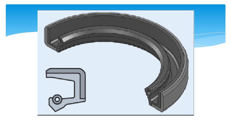
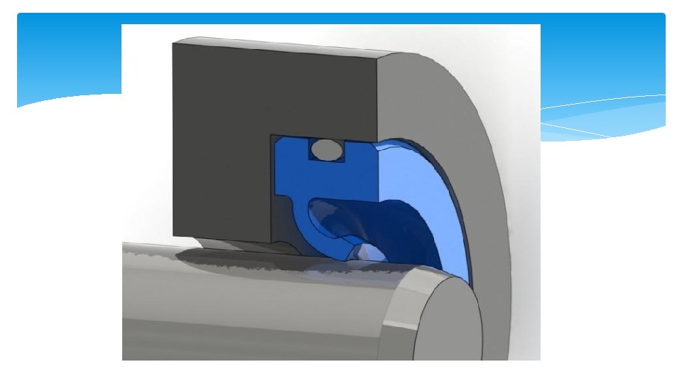
Lip Seals Lip seals work well in high speed low pressure rotating shafts
Main Application of Lip Seals Ball and roller bearing protection As little as 0. 002% water in lubrication oil can reduce ball bearing life by 50% Solid particles cause rapid damage to the bearing races.
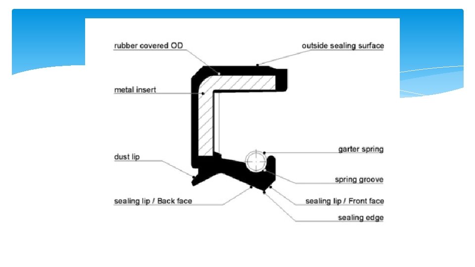
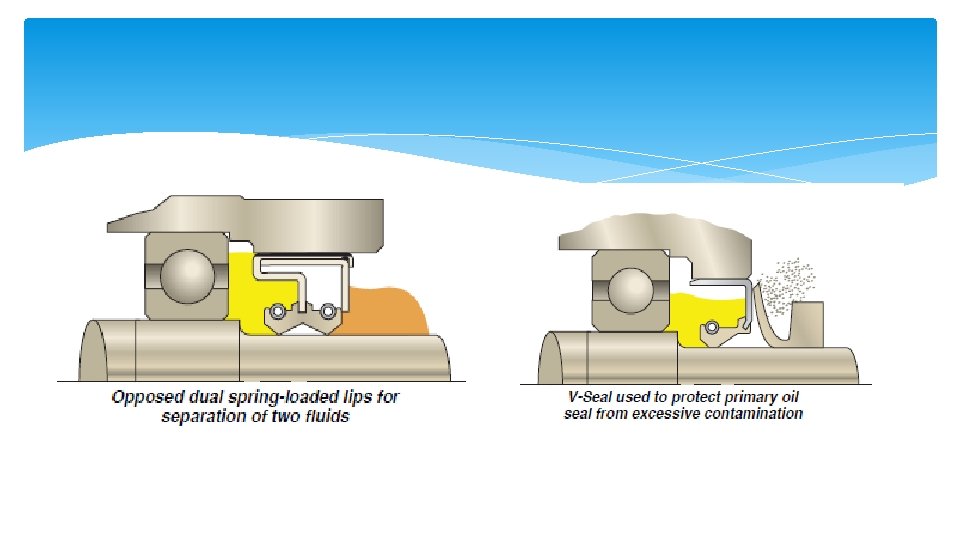
The purpose of the spring is to provide a uniform load on the lip Also overcomes compression set and wear of the lip material.
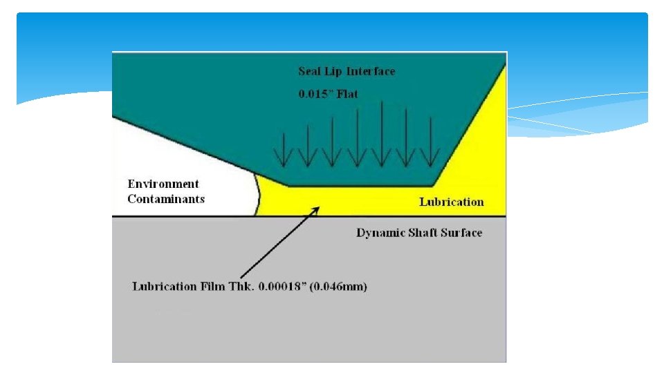
There is a tendency for liquids to be pumped from the low angle side towards the high angle side. Underneath the flattened area a thin fluid film is formed. Its thickness must be between 1 and 3 µm to avoid leakage
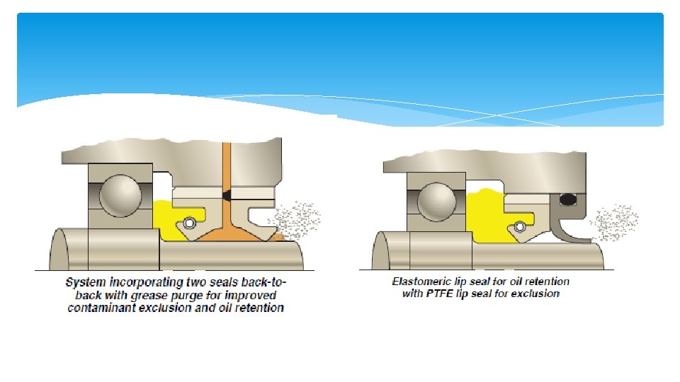
Primary function is retention Primary function is exclusion
Lip Seals To minimize wear The contact pressure should be as low as possible. Shaft surface should be smooth to 0. 25 - 0. 5 µm. There must be enough fluid to form a hydrodynamic film Fluid pressure must be low (0 -3 psi )
V-Seals
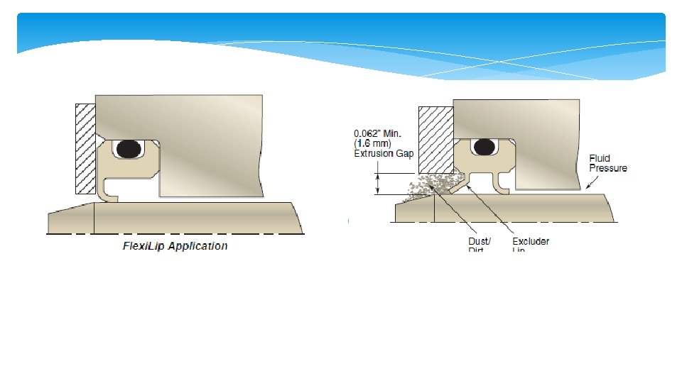
Flexi-Lip Rotary Seals Speeds up to 5000 fps Pressures up to 150 psi Material: PTFE, graphite
Metallic Seals Metallic seals go where polymers cannot High temperatures (Above 400 to 1800 Degree F) Cryogenic temperatures (below − 238 °F) High pressures (3000 psi to 60000 psi) High speeds
Metal Seals
C-Ring and Energized C-Ring
E-Ring and O-Ring
U-Ring and Metal Wire
Labyrinth Seals
Labyrinth Seal
Labyrinth Seal
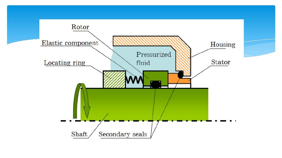
Mechanical Seals Rotating Elements