CSCE 230 Fall 2013 Chapter 6 Pipelining Mehmet


 to fetch instructions �A new instruction enters pipeline")


 Forwarding from Buffer 4 sub r 2, r 1, r")


![Conditional Branches �Consider a conditional branch instruction: Branch_if_[R 5]=[R 6] LOOP �Requires not only](https://slidetodoc.com/presentation_image_h2/9da5fd21d0121fed057853a1e15493b1/image-40.jpg "Conditional Branches �Consider a conditional branch instruction: Branch_if_[R 5]=[R 6] LOOP �Requires not only")


- Slides: 43
CSCE 230, Fall 2013 Chapter 6: Pipelining Mehmet Can Vuran, Instructor University of Nebraska-Lincoln Acknowledgement: Overheads adapted from those provided by the authors of the textbook
Chapter Outline �Pipelining: overlapped instruction execution �Hazards that limit pipelined performance gain �Hardware/software implications of pipelining �Influence of pipelining on instruction sets 2
Pipelining 3
Pipelining 4
Basic Concept of Pipelining �Circuit technology and hardware arrangement influence the speed of execution for programs �All computer units benefit from faster circuits �Pipelining involves arranging the hardware to perform multiple operations simultaneously �Similar to assembly line where product moves through stations that perform specific tasks �Same total time for each item, but overlapped 5
Pipelining in a Computer �Focus on pipelining of instruction execution �Multistage datapath in Chapter 5 consists of: Fetch, Decode, Execute, Memory, Write Back �Instructions fetched & executed one at a time with only one stage active in any cycle �With pipelining, multiple stages are active simultaneously for different instructions �Still 5 cycles to execute, but rate is 1 per cycle 7
8
Pipeline Organization �Use program counter (PC) to fetch instructions �A new instruction enters pipeline every cycle �Carry along instruction-specific information as instructions flow through the different stages �Use interstage buffers to hold this information �These buffers incorporate RA, RB, RM, RY, RZ, IR, and PC-Temp registers from Chapter 5 �The buffers also hold control signal settings 9
Stage 1 Stage 2 Stage 3 Stage 4 Stage 5 10
Instruction Fetch Adapting Chapter 5 Design to Pipeline Stage 1 IR Register File RA RB Instruction Decode Ctl 3 Ctl 4 Ctl 5 Stage 3 ALU RY Ctl 4 Ctl 5 Stage 4 MEM Access RZ Stage 2 Ctl 5 Stage 5
Specific Example sub r 2, r 1, r 3 and r 3, r 6, r 7 or r 2, r 4, r 5 add r 3, r 6, r 7 sw r 8, 100(r 9) Instruction Fetch add r 3, r 6, r 7 Register File RA RB Instruction Decode or r 2, r 4, r 5 Ctl 3 Ctl 4 Ctl 5 and r 3, r 6, r 7 Ctl 4 Ctl 5 Sub r 1, r 2, r 3 Ctl 5 ALU RY MEM access RZ
Pipelining Issues �Consider two successive instructions Ij and Ij 1 �Assume that the destination register of Ij matches one of the source registers of Ij 1 �Result of Ij is written to destination in cycle 5 �But Ij 1 reads old value of register in cycle 3 (1+2) �Due to pipelining, Ij 1 computation is incorrect �So stall (delay) Ij 1 until Ij writes the new value �Condition requiring this stall is a data hazard 13
Data Dependencies �Now consider the specific instructions Add R 2, R 3, #100 Subtract R 9, R 2, #30 �Destination R 2 of Add is a source for Subtract �There is a data dependency between them because R 2 carries data from Add to Subtract �On non-pipelined datapath, result is available in R 2 because Add completes before Subtract 14
Stalling the Pipeline �With pipelined execution, old value is still in register R 2 when Subtract is in Decode stage �So stall Subtract for 3 cycles in Decode stage �New value of R 2 is then available in cycle 6 15
Details for Stalling the Pipeline Control circuitry must recognize dependency while Subtract is being decoded in cycle 3 � Inter-stage buffers carry register identifiers for source(s) and destination of instructions � In cycle 3, compare destination identifier in Compute stage against source(s) in Decode � R 2 matches, so Subtract kept in Decode while Add allowed to continue normally � 16
Details for Stalling the Pipeline �Stall the Subtract instruction for 3 cycles by keeping contents of interstage buffer B 1 �What happens after Add leaves Compute? �Control signals are set in cycles 3 to 5 to create an implicit NOP (No-operation) in Compute �NOP control signals in interstage buffer B 2 create a cycle of idle time in each later stage �The idle time from each NOP is called a bubble 17
sub r 2, r 1, r 3 and r 12, r 5 or r 13, r 6, r 2 add r 14, r 2 sw r 15, 100($2) or r 13, r 6, r 2 Stalling: Example Instruction Fetch and r 12, r 5 Register File RA RB Instruction Decode sub r 2, r 1, r 3 Ctl 4 Ctl 5 ALU RY Ctl 4 Ctl 5 Memory Access RZ Ctl 5 Detect data dependency
sub r 2, r 1, r 3 and r 12, r 5 or r 13, r 6, r 2 add r 14, r 2 sw r 15, 100($2) or r 13, r 6, r 2 Stalling Instruction Fetch and r 12, r 5 Register File RA Instruction Decode Noop RB ALU RY sub r 2, r 1, r 3 Ctl 4 Ctl 5 Memory Access RZ Ctl 5 • Allow sub • Hold and • Create bubble
sub r 2, r 1, r 3 and r 12, r 5 or r 13, r 6, r 2 add r 14, r 2 sw r 15, 100($2) or r 13, r 6, r 2 Stalling Instruction Fetch and r 12, r 5 Register File RA Instruction Decode Noop RB • Bubble moves down the pipeline ALU Noop RY Memory Access RZ sub r 2, r 1, r 3 Ctl 5
sub r 2, r 1, r 3 and r 12, r 5 or r 13, r 6, r 2 add r 14, r 2 sw r 15, 100($2) Stalling or r 13, r 6, r 2 Instruction Fetch and r 12, r 5 Register File RA RB Instruction Decode Noop ALU RY Noop Memory Access RZ Noop • until completion of subtract
sub r 2, r 1, r 3 and r 12, r 5 or r 13, r 6, r 2 add r 14, r 2 sw r 15, 100($2) or r 13, r 6, r 2 Stalling Instruction Fetch and r 12, r 5 Register File RA RB Instruction Decode CTl 5 Ctl 4 Ctl 3 ALU RY Noop Memory Access RZ Noop • Now and can be decoded and proceed down the pipeline
Operand Forwarding �Operand forwarding handles dependencies without the penalty of stalling the pipeline �For the preceding sequence of instructions, new value for R 2 is available at end of cycle 3 �Forward value to where it is needed in cycle 4 23
Details for Operand Forwarding �Introduce multiplexers before ALU inputs to use contents of register RZ as forwarded value �Control circuitry now recognizes dependency in cycle 4 when Subtract is in Compute stage �Interstage buffers still carry register identifiers �Compare destination of Add in Memory stage with source(s) of Subtract in Compute stage �Set multiplexer control based on comparison 24
add r 14, r 2 Forwarding from Buffer 3 sub r 2, r 1, r 3 and r 12, r 5 or r 13, r 6, r 2 add r 14, r 2 sw r 15, 100($2) Instruction Fetch or r 13, r 6, r 2 Register File Instruction Decode muxes RA RB and r 12, r 5 Ctl 3 Ctl 4 Ctl 5 ALU RY sub r 2, r 1, r 3 Ctl 4 Ctl 5 Memory Access RZ Ctl 5
26
sw r 15, 100($2) Forwarding from Buffer 4 sub r 2, r 1, r 3 and r 12, r 5 or r 13, r 6, r 2 add r 14, r 2 sw r 15, 100($2) Instruction Fetch add r 14, r 2 Register File Instruction Decode muxes RA RB or r 13, r 6, r 2 Ctl 3 Ctl 4 Ctl 5 ALU RY and r 12, r 5 Ctl 4 Ctl 5 Memory Access RZ sub r 2, r 1, r 3 Ctl 5
Software Handling of Dependencies �Compiler can generate & analyze instructions �Data dependencies are evident from registers �Compiler puts three explicit NOP instructions between instructions having a dependency �Delay ensures new value available in register but causes total execution time to increase �Compiler can optimize by moving instructions into NOP slots (if data dependencies permit) 28
29
Memory Delays �Memory delays can also cause pipeline stalls �A cache memory holds instructions and data from the main memory, but is faster to access �With a cache, typical access time is one cycle �But a cache miss requires accessing slower main memory with a much longer delay �In pipeline, memory delay for one instruction causes subsequent instructions to be delayed 30
31
Memory Delays � Even with a cache hit, a Load instruction may cause a short delay due to a data dependency � One-cycle stall required for correct value to be forwarded to instruction needing that value � Optimize with useful instruction to fill delay Forwarded from Stage 4 32
A Code Schedule with Stalls �C code for A stall lw lw add sw r 2, r 3, r 4, r 5, r 6, = B + E; C = B + F; 0(r 1) 4(r 1) r 2, r 3 12(r 1) 8(r 1) r 2, r 5 16(r 1) Does this code require Forwarding to work? If so, where? 13 cycles 33
Reordering Code to Avoid Stalls �Reorder code to avoid use of load result in the next instruction �C code for A = B + E; C = B + F; stall lw lw add sw r 2, r 3, r 4, r 5, r 6, 0(r 1) 4(r 1) r 2, r 3 12(r 1) 8(r 1) r 2, r 5 16(r 1) 13 cycles lw lw lw add sw r 2, r 3, r 5, r 4, r 6, 0(r 1) 4(r 1) 8(r 1) r 2, r 3 12(r 1) r 2, r 5 16(r 1) 11 cycles 34
Reading Assignment �For more analysis of the impacts of various delays and hazards on pipeline performance, Read Section 6. 8. 1. 38
Branch Delays �Ideal pipelining: fetch each new instruction while previous instruction is being decoded �Branch instructions alter execution sequence, but they must be processed to determine the effect �Any delay for determining branch outcome leads to an increase in total execution time �Techniques to mitigate this effect are desired �Understand branch behavior to find solutions
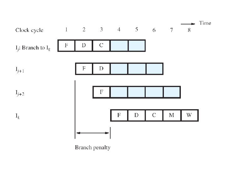
Unconditional Branches �Consider instructions Ij , Ij 1 , Ij 2 in sequence �Ij is an unconditional branch with target Ik �In Chapter 5, the Compute stage determined the target address using offset and PC 4 value �In pipeline, target Ik is known for Ij in cycle 4, but instructions Ij 1 , Ij 2 fetched in cycles 2 & 3 �Target Ik should have followed Ij immediately, so discard Ij 1 , Ij 2 and incur two-cycle penalty
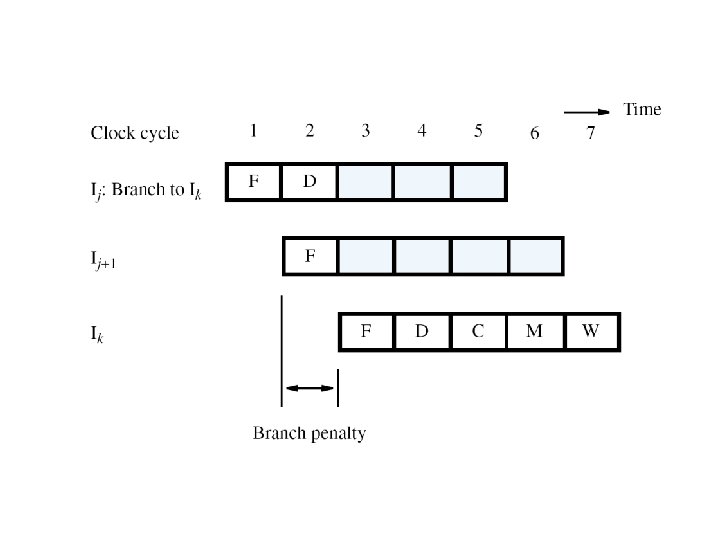
Reducing the Branch Penalty �In pipeline, adder for PC is used every cycle, so it cannot calculate the branch target address �So introduce a second adder just for branches �Place this second adder in the Decode stage to enable earlier determination of target address �For previous example, now only Ij 1 is fetched �Only one instruction needs to be discarded �The branch penalty is reduced to one cycle
Conditional Branches �Consider a conditional branch instruction: Branch_if_[R 5]=[R 6] LOOP �Requires not only target address calculation, but also requires comparison for condition �In Chapter 5, ALU performed the comparison �Target address now calculated in Decode stage �To maintain one-cycle penalty, introduce a comparator just for branches in Decode stage
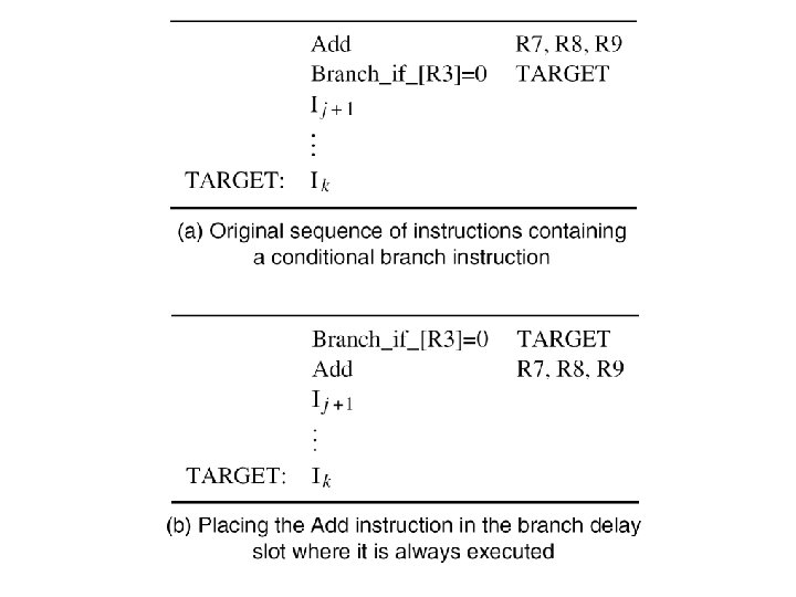
The Branch Delay Slot �Let both branch decision and target address be determined in Decode stage of pipeline �Instruction immediately following a branch is always fetched, regardless of branch decision �That next instruction is discarded with penalty, except when conditional branch is not taken �The location immediately following the branch is called the branch delay slot
The Branch Delay Slot �Instead of conditionally discarding instruction in delay slot, always let it complete execution �Let compiler find an instruction before branch to move into slot, if data dependencies permit �Called delayed branching due to reordering �If useful instruction put in slot, penalty is zero �If not possible, insert explicit NOP in delay slot for one-cycle penalty, whether or not taken