
Topics Low power design n Pipelining n FPGABased
Topics Low power design. n Pipelining. n FPGA-Based System Design: Chapter 6 Copyright 2004 Prentice Hall PTR
Rules for reducing power consumption. n Turn it off. – Eliminates leakage current. n Slow it down, reduce voltage. – Performance is linear with clock frequency. – Power is V 2. n Don’t change its inputs. – Activity-dependent. FPGA-Based System Design: Chapter 6 Copyright 2004 Prentice Hall PTR
Energy and power Energy = power * time. n Energy consumption is critical for batterypowered systems. n Power consumption is critical for heat dissipation limited systems. n FPGA-Based System Design: Chapter 6 Copyright 2004 Prentice Hall PTR
Energy and performance n In many cases, high performance = low energy. – Efficiency pays off in both arenas. n In some cases, energy can be saved by reducing performance. – P = 1/2 CV 2 – Power goes down faster than performance. FPGA-Based System Design: Chapter 6 Copyright 2004 Prentice Hall PTR
Levels of abstraction n Physical: – Minimize capacitance. n Gate: – Use low leakage gates. n Combinational: – Avoid twitches. n Register-transfer: – Avoid using units. n Architecture: – Slow things down, turn them off. FPGA-Based System Design: Chapter 6 Copyright 2004 Prentice Hall PTR
Sources of energy consumption n Static: – Leakage. n Dynamic: – Switching activity. FPGA-Based System Design: Chapter 6 Copyright 2004 Prentice Hall PTR
Physical optimizations Assuming equal signal probabilities, total wire capacitance is proportional to dynamic power consumption. n Shorter wires -> less power consumption. n More active nets should be shortened first. n FPGA-Based System Design: Chapter 6 Copyright 2004 Prentice Hall PTR
How to reduce wire length Use hard macros where possible. n Add placement constraints. n Use design hierarchy to guide placement search. n Use nets with small drivers where possible. n – Don’t drive a net faster than it needs to go. FPGA-Based System Design: Chapter 6 Copyright 2004 Prentice Hall PTR
Logic/circuit optimizations n Turn off gate where possible. – Not an option in most FPGAs, but it should be. n Operate gate at low voltage. – Speed decreases linearly, power decreases as V 2. FPGA-Based System Design: Chapter 6 Copyright 2004 Prentice Hall PTR
Combinational optimizations n Design network to avoid unnecessary glitching where possible. – Balance delays across paths. n Can duplicate logic to reduce wire lengths. – Does the duplicate logic use less power than the wire? FPGA-Based System Design: Chapter 6 Copyright 2004 Prentice Hall PTR
Register-transfer optimizations n Hold inputs when a unit’s output will not be used. – Put register at inputs. n Turn off units when they won’t be used for several cycles. – Can’t selectively turn off LEs in most FPGAs. FPGA-Based System Design: Chapter 6 Copyright 2004 Prentice Hall PTR
Architectures for low power n Two important methods: – architecture-driven voltage scaling – power-down modes FPGA-Based System Design: Chapter 6 Copyright 2004 Prentice Hall PTR
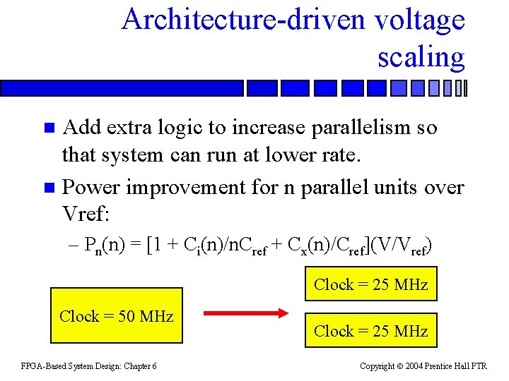
Architecture-driven voltage scaling Add extra logic to increase parallelism so that system can run at lower rate. n Power improvement for n parallel units over Vref: n – Pn(n) = [1 + Ci(n)/n. Cref + Cx(n)/Cref](V/Vref) Clock = 25 MHz Clock = 50 MHz FPGA-Based System Design: Chapter 6 Clock = 25 MHz Copyright 2004 Prentice Hall PTR
Power-down modes n CMOS doesn’t consume power when not transitioning. Many systems can incorporate power-down modes: – condition the clock on power-down mode; – add state to control for power-down mode; – modify the control logic to ensure that powerdown/power-up don’t corrupt control state. FPGA-Based System Design: Chapter 6 Copyright 2004 Prentice Hall PTR
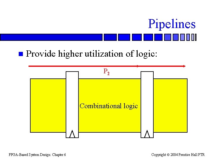
Pipelines n Provide higher utilization of logic: P 21 Combinational logic FPGA-Based System Design: Chapter 6 Copyright 2004 Prentice Hall PTR
Pipeline metrics n Throughput: rate at which new values enter the system. – Initiation interval: time between successive inputs. n Latency: delay from input to output. FPGA-Based System Design: Chapter 6 Copyright 2004 Prentice Hall PTR
Simple pipelines Pure pipelines have no control. n Choose latency, throughput. n Choose register locations with retiming. n Overhead: n – Setup, hold times. – Power. FPGA-Based System Design: Chapter 6 Copyright 2004 Prentice Hall PTR
Complex pipelines Actions in pipeline depend on data or external events. n Actions on pipe: n – Stall values. – Abort operation. – Bypass values. FPGA-Based System Design: Chapter 6 Copyright 2004 Prentice Hall PTR
Pipeline metrics n Ignore register delay: – Combinational logic delay D. – Latency L. – Throughput T. n Delay through unpipelined system. – L = D. – T = 1/D. FPGA-Based System Design: Chapter 6 Copyright 2004 Prentice Hall PTR
Adding pipeline stages n Add a pipeline stage: – Latency remains L = D. – Throughput increases: T = 2/D. n n-stage pipeline: – Throughput increases: T = n/D. n Clock period: – P = D/n. FPGA-Based System Design: Chapter 6 Copyright 2004 Prentice Hall PTR
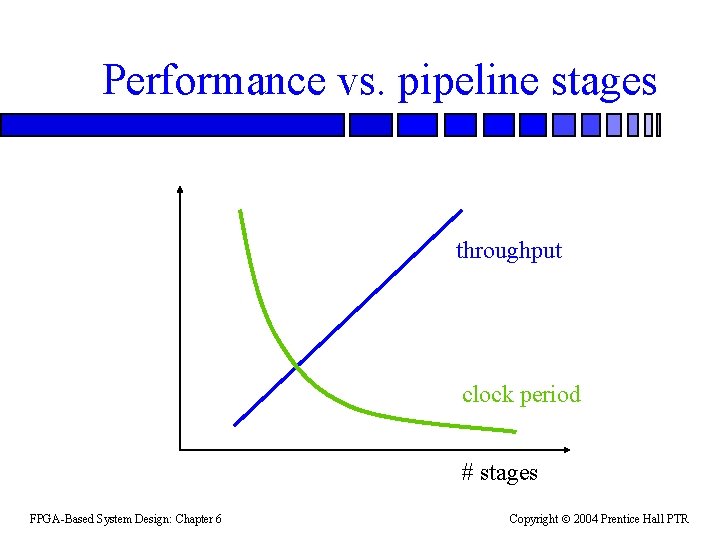
Performance vs. pipeline stages throughput clock period # stages FPGA-Based System Design: Chapter 6 Copyright 2004 Prentice Hall PTR
Adding pipeline stages n Must add a pipeline stage that cuts the logic. – Cutset for PI-PO graph. n Can use retiming to position the registers in the logic. FPGA-Based System Design: Chapter 6 Copyright 2004 Prentice Hall PTR
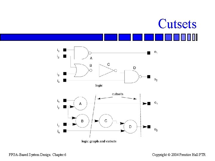
Cutsets FPGA-Based System Design: Chapter 6 Copyright 2004 Prentice Hall PTR
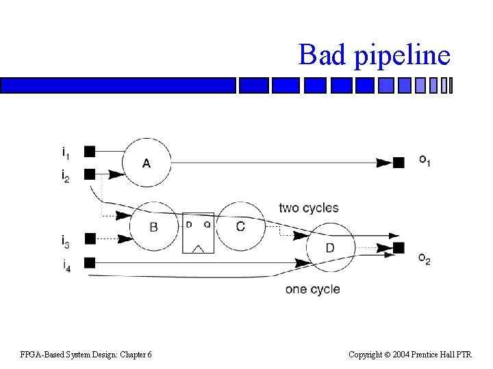
Bad pipeline FPGA-Based System Design: Chapter 6 Copyright 2004 Prentice Hall PTR
Pipeline utilization n Need to fill up the pipeline. – Later stages are unused as the pipeline fills up. n Assume D stages of valid data, n total stages. – Utilization U= D / D+n. n In steady state, utilization approaches 1. FPGA-Based System Design: Chapter 6 Copyright 2004 Prentice Hall PTR
Pipelines with control n Pipeline may do different things at different times. – CPU control flow. n Must make sure that the pipeline operates properly in all cases. FPGA-Based System Design: Chapter 6 Copyright 2004 Prentice Hall PTR
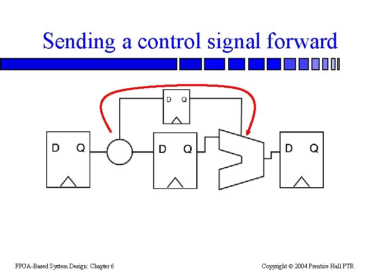
Sending a control signal forward FPGA-Based System Design: Chapter 6 Copyright 2004 Prentice Hall PTR
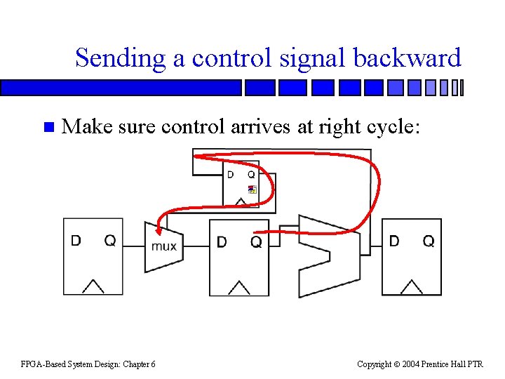
Sending a control signal backward n Make sure control arrives at right cycle: FPGA-Based System Design: Chapter 6 Copyright 2004 Prentice Hall PTR
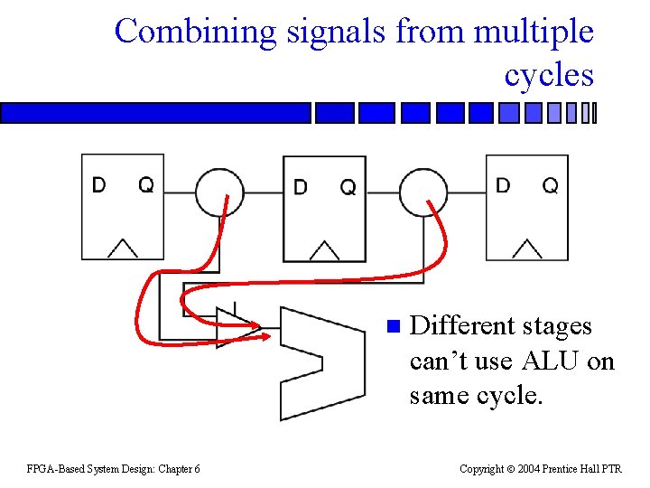
Combining signals from multiple cycles n FPGA-Based System Design: Chapter 6 Different stages can’t use ALU on same cycle. Copyright 2004 Prentice Hall PTR
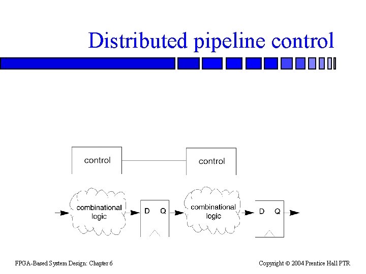
Distributed pipeline control FPGA-Based System Design: Chapter 6 Copyright 2004 Prentice Hall PTR
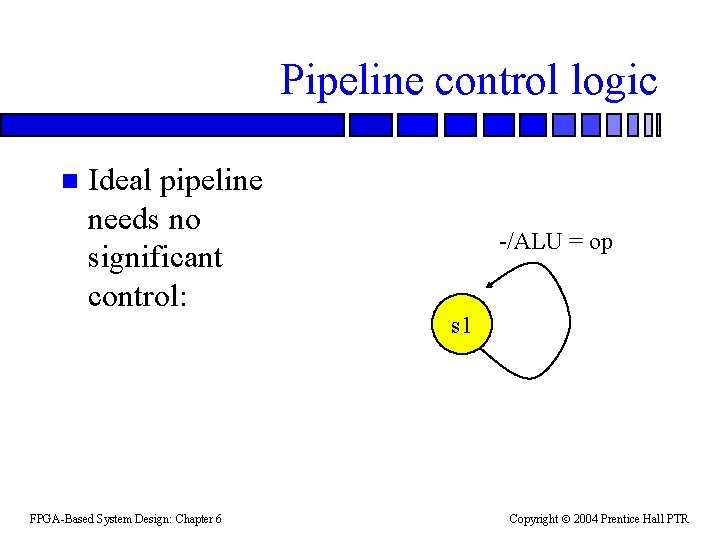
Pipeline control logic n Ideal pipeline needs no significant control: FPGA-Based System Design: Chapter 6 -/ALU = op s 1 Copyright 2004 Prentice Hall PTR
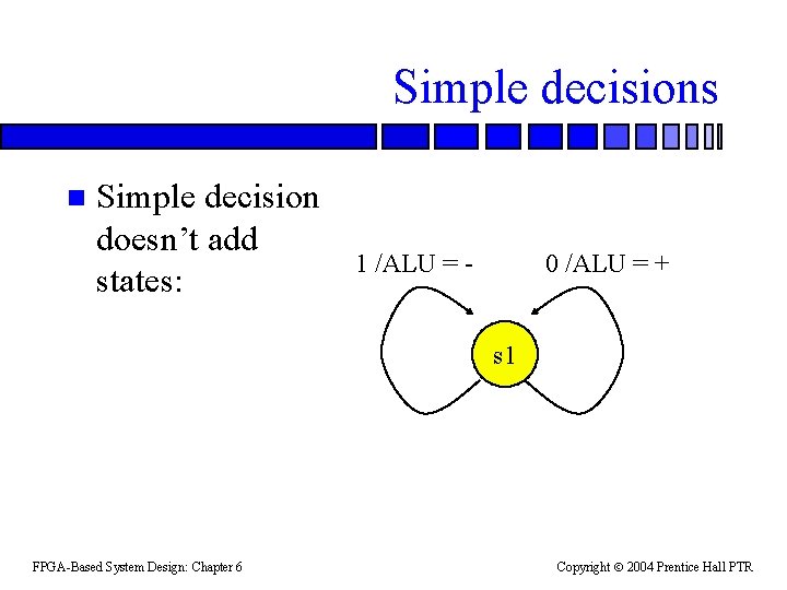
Simple decisions n Simple decision doesn’t add states: 1 /ALU = - 0 /ALU = + s 1 FPGA-Based System Design: Chapter 6 Copyright 2004 Prentice Hall PTR
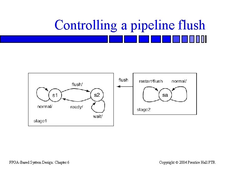
Controlling a pipeline flush FPGA-Based System Design: Chapter 6 Copyright 2004 Prentice Hall PTR
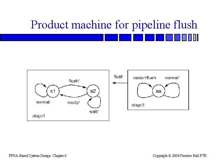
Product machine for pipeline flush FPGA-Based System Design: Chapter 6 Copyright 2004 Prentice Hall PTR
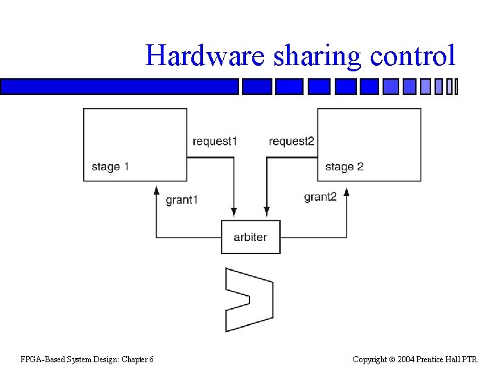
Hardware sharing control FPGA-Based System Design: Chapter 6 Copyright 2004 Prentice Hall PTR
Pipeline verification n Extensive simulation is required to exercise the pipeline. – State of pipeline stages interact. n Symbolic simulation: simulate names, not particular values. FPGA-Based System Design: Chapter 6 Copyright 2004 Prentice Hall PTR
- Slides: 36