Course Overview DNT 354 CONTROL PRINCIPLE Date 06062018


 CO 1 CO 2 Able to develop mathematical model for specific")


 Mid Term Examinatio n Final Examinatio n 4")
 Analyze and compute transient response and")


 ii. Remote Control iii. Robotic arm")
 ii. Cornellis Drebbel (17 th")


- Slides: 42
Course Overview DNT 354 – CONTROL PRINCIPLE Date: 06/06/2018 Prepared by: Nor Shaifudin Bin Abdul Hamid Email: norshaifudin@unimap. edu. my
COURSE SYNOPSIS Provides a background of control principles in various engineering applications. Basic mathematical tools such as Laplace transform, transfer function, block diagram, signal flow graph, mathematical modeling of dynamic systems, time response analysis, stability of linear system, root locus and frequency domain analysis are utilized.
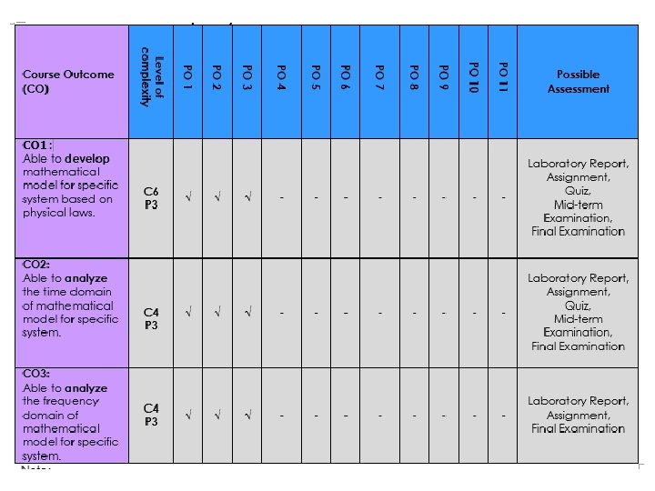
COURSE OUTCOMES (CO) CO 1 CO 2 Able to develop mathematical model for specific system based on physical laws. Able to analyze the time domain of mathematical model for specific system. CO 3 Able to analyze the frequency domain of mathematical model for specific system.
COURSE EVALUATION Final Examination : : : Lab Reports Mid-Semester Test Quizzes Assignments : 50% 10% 20% 10% Total Mark : 100% :
LIST OF REFERENCES Textbook i. Norman S. Nise: Control System Engineering - 7 th Ed. , John Wiley & Sons, 2018. References i. iii. iv. S. K. Bhattacharya : Control Systems Engineering - 3 rd Ed. , Pearson India, 2013. Richard C. Dorf & Robert H. Bishop: Modern Control Systems - 12 th Ed. , Prentice Hall, 2011. Ogata, Katsuhito: Modern Control Engineering - 5 th Ed. , Prentice Hall, 2010. Franklin G. F. , Power J. D & Emami-Naeini A. : Feedback Control of Dynamic Systems - 6 th Ed. , Addision Wesley, 2009.
ACADEMIC STAFF MEMBERS Lecture Session En. Nor Shaifudin Bin Abdul Hamid Dr. Allan Melvin A/L Andrew Laboratory Session En. Nor Shaifudin Bin Abdul Hamid Dr. Allan Melvin A/L Andrew
TEACHING PLAN Minggu Content outline of the course/module and the SLT per topic : /Study Mod Kaedah Week Penyampaian / Penilaian/ Delivery Mode Possible Topik/Topic Assessment Methods Introduction to Control Systems 1 Lecture (C 3) Mid Term Examination Final Examination 3 Lecture (C 4) Assignment 1 Quiz 1 Mid Term Examination Final Examination 7 7 14 Week 3 : Tutorial 1 2 2 4 Week 4 : Tutorial 2 2 2 4 Explain several terms of dynamic system. Define basic concepts of control systems. Analyze control system examples, types and effects of control system in various applications. Mathematical Models of System 2 -4 Bersemuka / Face to face (Jam/Hours) Jumlah Jam Pembelajaran / Sendiri/ Self Total Learning (SL) Learning (Jam/Hours) Time (TLT) (Jam/Hours) 3 6 Analyze and discuss differential equation, partial fraction expantion, Laplace transform , Inverse Laplace, transfer function, block diagram and signal-flow graph model for specific system.
Modeling Dynamic Systems Lecture (C 6) Mid Term Examinatio n Final Examinatio n 4 4 8 Week 5: Lab 1: Open Loop Characteristics Analysis Laboratory (P 3) Laboratory report 2 1. 32 3. 32 Week 6: Lab 2: Closed Loop Characteristics Analysis Laboratory (P 3) Laboratory report 2 1. 32 3. 32 Time –Domain Analysis Lecture (C 4) Mid Term Examination Final Examination 3 3 6 Develop the mathematical modeling of dynamic systems such as mechanical and electrical system based on transfer function approach. 5 -6 7 Analyze and compute transient response and steady state response analysis of first-order and second order systems. Discuss the first-order and second-order performances. Describe the concept of stability. Discuss and solve the Routh-Hurwitz stability criterion. Describe the concept of root locus and discuss the root locus procedure. CUTI PERTENGAHAN SEMESTER / MID SEMESTER BREAK
Time –Domain Analysis 8 -10 Lecture (C 4) Analyze and compute transient response and steady state response analysis of first-order and second order systems. Discuss the first-order and second-order performances. Describe the concept of stability. Discuss and solve the Routh-Hurwitz stability criterion. Describe the concept of root locus and discuss the root locus procedure. Assignment 2 Quiz 2 Final Examination 6 6 12 2 2 4 2 1. 32 3. 32 2 2 4 Final Examination 7 7 14 Laboratory report 2 1. 32 3. 32 2 4 3 6 Week 8 : Tutorial 3 Week 9: Lab 3: Time Domain Analysis (Root Locus) Laboratory (P 3) Laboratory report Week 10 : Tutorial 4 Lecture (C 4) Frequency Domain Analysis Analyze and discuss bode diagram representation of the frequency response. Define and calculate phase and gain 11 -13 margin. 14 Week 11: Lab 4: Frequency Response Using Bode Plot Week 12 : Tutorial 5 Laboratory (P 3) Controller Lecture (C 3) Describe basic Controller. introduction to 2 PID Final Examination 3
LAB SESSIONS Lab Title 1 Open-loop Systems Characteristics 2 Closed-loop Systems Characteristics 3 Time Domain Analysis 4 Frequency Domain Analysis
Introduction to Control System DNT 354 – CONTROL PRINCIPLE Date: 06/06/2018 Prepared by: Nor Shaifudin Bin Abdul Hamid Email: norshaifudin@unimap. edu. my
CONTENTS Basic Concepts Control System Examples Control System Design
BASIC CONCEPTS System A collection of components which are coordinated together to perform a function. Dynamic System A system with a memory. For example, the input value at time t will influence the output at future instant. A system interact with their environment through a controlled boundary.
BASIC CONCEPTS The interaction is defined in terms of variables. i. iii. System input System output Environmental disturbances
SYSTEM VARIABLES The system’s boundary depends upon the defined objective function of the system. The system’s function is expressed in terms of measured output variables. The system’s operation is manipulated through control input variables. The system’s operation is also affected in an uncontrolled manner through disturbance input variables.
CONTROL SYSTEM Control is the process of causing a system variable to conform to some desired value. Manual control Automatic control (involving machines only). A control system is an interconnection of components forming a system configuration that will provide a desired system response. Input Signal Control System Energy Source Output Signal
MANUAL VS AUTOMATIC CONTROL Control is a process of causing a system variable such as temperature or position to conform to some desired value or trajectory, called reference value or trajectory. For example, driving a car implies controlling the vehicle to follow the desired path to arrive safely at a planned destination. i. If you are driving the car yourself, you are performing manual control of the car. ii. If you use design a machine, or use a computer to do it, then you have built an automatic control system.
RESPONSE CHARACTERISTICS Transient response: Steady-state response: Gradual change of output from initial to the desired condition Approximation to the desired response For example, consider an elevator rising from ground to the 4 th floor.
BLOCK DIAGRAM Component or process to be controlled can be represented by a block diagram. The input-output relationship represents the cause and effect of the process. Input Process Output Control systems can be classified into two categories: i. Open-loop control system ii. Closed-loop feedback control system
CONTROL SYSTEM CLASSIFICATION An open-loop control system utilizes an actuating device to control the process directly without using feedback. Desired Output Response Actuating Device Process Output A closed-loop feedback control system uses a measurement of the output and feedback of the output signal to compare it with the desired output or reference. Desired Output Respons e Compariso n Controller Process Measurement Single Input Single Output (SISO) System Output
CONTROL SYSTEM CLASSIFICATION Missile Launcher System Open-Loop Control System
CONTROL SYSTEM CLASSIFICATION Missile Launcher System Closed-Loop Feedback Control System
CONTROL SYSTEM CLASSIFICATION Desired Output Respons e Controller Process Measurement Multi Input Multi Output (MIMO) System Output Variable s
PURPOSE OF CONTROL SYSTEMS i. Power Amplification (Gain) ii. Remote Control iii. Robotic arm used to pick up radioactive materials Convenience of Input Form iv. Positioning of a large radar antenna by low-power rotation of a knob Changing room temperature by thermostat position Compensation for Disturbances Controlling antenna position in the presence of large wind disturbance torque
HISTORICAL DEVELOPMENTS i. Ancient Greece (1 to 300 BC) ii. Cornellis Drebbel (17 th century) iii. Temperature control James Watt (18 th century) iv. Water float regulation, water clock, automatic oil lamp Flyball governor Late 19 th to mid 20 th century Modern control theory
WATT’S FLYBALL GOVERNOR
TEMPERATURE CONTROL Figure shows a schematic diagram of temperature control of an electric furnace. The temperature in the electric furnace is measured by a thermometer, which is analog device. The analog temperature is converted to a digital temperature by an A/D converter. The digital temperature is fed to a controller through an interface. This digital temperature is compared with the programmed input temperature, and if there is any error , the controller sends out a signal to the heater, through an interface, amplifier and relay to bring the furnace temperature to a desired value.
TRANSPORTATION Car and Driver Objective: To control direction and speed of car Outputs: Actual direction and speed of car Control inputs: Road markings and speed signs Disturbances: Road surface and grade, wind, obstacles Possible subsystems: The car alone, power steering system, breaking system
TRANSPORTATION Functional block diagram: Desired course of travel + Error - Driver Steering Mechanism Automobile Measurement, visual and tactile Time response: Actual course of travel
TRANSPORTATION Consider using a radar to measure distance and velocity to autonomously maintain distance between vehicles. Automotive: Engine regulation, active suspension, anti-lock breaking system (ABS) Steering of missiles, planes, aircraft and ships at sear.
PROCESS INDUSTRY Control used to regulate level, pressure and pressure of refinery vessel. Coordinated control system for a boilergenerator. For steel rolling mills, the position of rolls is controlled by the thickness of the steel coming off the finishing line.
MANUFACTURING INDUSTRY Consider a three-axis control system for inspecting individual semiconducting wafers with a highly sensitive camera
HOMES i. CD Players ii. The position of the laser spot in relation to the microscopic pits in a CD is controlled. Air-Conditioning System Uses thermostat and controls room temperature.
CONTROL SYSTEM COMPONENTS i. System, plant or process ii. Actuators iii. Converts the control signal to a power signal Sensors iv. To be controlled Provides measurement of the system output Reference input Represents the desired output
GENERAL CONTROL SYSTEM Disturbance Set-point or Reference input + Error - + Controlled Signal Controller Feedback Signal Manipulated Variable Actuator Sensor + + + Process Actual Output
CONTROL SYSTEM DESIGN PROCESS 1. Establish control goals 2. Identify the variables to control 3. Write the specifications for the variables 4. Establish the system configuration and identify the actuator If the performance does not meet specifications, then iterate the configuration and actuator 5. Obtain a model of the process, the actuator and the sensor 6. Describe a controller and select key parameters to be adjusted 7. Optimize the parameters and analyze the performance If the performance meet the specifications, then finalize design
TURNTABLE SPEED CONTROL Application: CD player, computer disk drive Requirement: Constant speed of rotation Open loop control system: Block diagram representation:
TURNTABLE SPEED CONTROL Closed-loop control system: Block diagram representation:
DISK DRIVE READ SYSTEM Goal of the system: Position the reader head in order to read data stored on a track. Variables to control: Position of the reader head
DISK DRIVE READ SYSTEM Specification: i. Speed of disk: 1800 rpm to 7200 rpm ii. Distance head-disk: Less than 100 nm iii. Position accuracy: 1 µm iv. Move the head from track ‘a’ to track ‘b’ within 50 ms System Configuration:
FURTHER READING… Textbook i. Norman S. Nise: Control System Engineering - 7 th Ed. , John Wiley & Sons, 2018. References i. iii. iv. S. K. Bhattacharya : Control Systems Engineering - 3 rd Ed. , Pearson India, 2013. Richard C. Dorf & Robert H. Bishop: Modern Control Systems - 12 th Ed. , Prentice Hall, 2011. Ogata, Katsuhito: Modern Control Engineering - 5 th Ed. , Prentice Hall, 2010. Franklin G. F. , Power J. D & Emami-Naeini A. : Feedback Control of Dynamic Systems - 6 th Ed. , Addision Wesley, 2009.