DNT 111 DRAWING ENGINEERING PROJECTION SYSTEMS What is


 * At least 2 view to represent an object, but")


- Slides: 26
DNT 111 DRAWING ENGINEERING PROJECTION SYSTEMS
What is Orthographic Projection? Orthographic Projection is a method of representing a three dimensional object on paper using several two dimensional views. It is the international language of Engineers and Designers
How does it work? We look directly at the different faces of the object (90˚ to the face) and draw the lines that we see.
How many views? One view is never enough to describe an object. We need at least two views to accurately describe even the most simple of objects but generally we use three views You can use as many views as the object requires. ( if the object is to complex)
1 side (Top view) * At least 2 view to represent an object, but generally using 3 view.
The Glass Box concept Imagine that the object you are going to draw is positioned inside a glass box, so that the large flat surfaces of the object are parallel to the walls of the box. From each point on the object, imagine a ray, or projector perpendicular to the wall of the box forming the view of the object on that wall or projection plane.
The Glass Box
Standard 2 D views
Method of representation. The methods of orthographic representation are third angle projection, first-angle projection. Third-angle projection is used in the US, Canada, and many other countries throughout the world. First-angle projection is used mainly in European and Asian countries. 9
How do I know which method is being used? Each method has its own symbol and they are as follows First angle projection Third angle projection
How do I draw this symbol? The recommended proportions for the symbol are as follows
First angle & Third Angle projection
First Angle Projection
ü Object is placed above the horizontal plane & in front of vertical plane
Third Angle Projection Object is placed below the horizontal plane & behind vertical plane
Symbols for 1 st & 3 rd Angle Projection Third angle projection is used in the U. S. , and Canada
Standard Views of Primitive Solids
How to convert 3 D Isometric Diagram into 2 D Orthographic Views…….
How to construct an orthographic drawing. . .
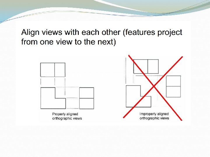
View Orientation Poor orientation Good orientation
View Selection Select the most descriptive views Use minimum number of views to describe the object
Miter lines
Conventional Practices - Tangency
Side view Draw the following views in first angle and third angle projection -Front View from A - Side View - Top View Fully dimension and identify the drawing
Assignment. . .