CNC Turning Module 3 CNC Turning Machine Watch


 machine")
 machine:")
 machine:")


: To run the")

: Is used")

![Example solution Close the door Select MDI mode Press the [PROG] from function keys](https://slidetodoc.com/presentation_image_h2/c0ba0722cb40ba82f60b0f91150c1901/image-35.jpg "Example solution Close the door Select MDI mode Press the [PROG] from function keys")


.")

 Ø Reference the machine in")

 ON Ø Switch coolant OFF Ø Select")


- Slides: 55
CNC Turning Module 3: CNC Turning Machine
Watch the following video
Module Objectives Ø Describe the main parts of the EMCO CNC turning machine. Ø Operate the EMCO CNC turning machine. Ø Identify the main reference points on the EMCO CNC turning machine. Ø Distinguish the main control keys and their functions. Ø Run the spindle of the Emco machine to a specific speed. Ø Reference the machine in X and Z. Ø Select the proper mode to move the tool turret in X and Z. Ø Set the required tool in the active position. Ø Decrease/Increase the feed rate in a specific percentage.
Main parts of the Turning (Lathe) machine
Main parts of the Turning (Lathe) machine:
Main parts of the Turning (Lathe) machine:
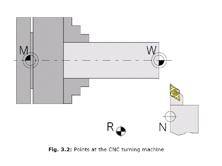
Points on the CNC Machine
Points on the CNC Machine Zero Point Reference Zero Point Work piece Zero Point Tool Holder Zero Point
Switching the Machine ON and OFF
To switch the machine ON: - Open air supply -Switch on the main switch at the E-cabinet - Turn on the PC - Launch Control Software - Open and close the chip guard door once for checking the door safety switch
To switch the machine OFF: - Terminate control software - Terminate Windows - Switch off main switch - Lock air supply
Main Control Keys
Machine control keyboard: Machine control keyboard of the EMCO PC-Turn Series
Machine control keyboard of the EMCO PC-Turn Series Skip blocks will not be executed
Machine control keyboard of the EMCO PC-Turn Series Test run of programs, in which the program will run while the spindle is not rotating and there is no workpiece in the clamping device.
Machine control keyboard of the EMCO PC-Turn Series Reset
Machine control keyboard of the EMCO PC-Turn Series Stop the program
Machine control keyboard of the EMCO PC-Turn Series Start the program
Machine control keyboard of the EMCO PC-Turn Series Manual axis direction movement
Machine control keyboard of the EMCO PC-Turn Series Approaching the reference point in all axes
Machine control keyboard of the EMCO PC-Turn Series Open / Close door
Machine control keyboard of the EMCO PC-Turn Series Open / Close clamping device
Machine control keyboard of the EMCO PC-Turn Series Swivel tool turret
Machine control keyboard of the EMCO PC-Turn Series Coolant/ Puff Blowing On / Off
Machine control keyboard of the EMCO PC-Turn Series Spindle speed override (increase or decrease the spindle speed)
Machine control keyboard of the EMCO PC-Turn Series Feed override switch (increase or decrease the feed rate)
Machine control keyboard of the EMCO PC-Turn Series Mode selector provides several operating modes : REF, MEM, EDIT, MDI, JOG, and INC mode
Machine control keyboard of the EMCO PC-Turn Series REF: Referencing Manual referencing - Press the –Z or +Z key: the slide traverses to the reference point in Z. - Press the -X or +X key: the slide traverses to the reference point in X.
Machine control keyboard of the EMCO PC-Turn Series REF: Referencing Automatic referencing: - Select REF Mode: - Press the reference key : The slides traverse to the reference point in both axis, one after the other.
Machine control keyboard of the EMCO PC-Turn Series MEM (Memory Mode): To run the program in automatic mode.
Machine control keyboard of the EMCO PC-Turn Series EDIT: Allows the addition, modification, and deletion of programs.
Machine control keyboard of the EMCO PC-Turn Series MDI: (Manual Data Input): Is used when the user wishes to manually input program commands into the system. The programs are typed directly into the system via MDI keypad.
Examples To run the spindle at 1000 RPM in clockwise direction
Example solution Close the door Select MDI mode Press the [PROG] from function keys Use Data Input Keys to write the following block: S 1000 M 3 (then press INPUT key) Press Start Press reset to stop the program
Example solution Press POS • JOG: In this mode the slides can be moved in one axis at a time by use of the Axis Direction Keys. • INC (Incremental): In this mode the slides can be moved certain distances in micron.
Notes The machine is switched off by means of the main switch. It is recommended to switch off the machine only in inoperative position of the tool turret. Operation is interrupted by means of the reset key. All current machine functions are interrupted with RESET.
Function Keys
Function Keys enable the user to know the current positions of the tool, deal with programs, make the necessary setting e. g workpiece and tool settings, control program simulation, . … etc.
Data Input keys
Data input keys runs several functions (numbers, address characters).
Machine Practical Tasks (Before performing these tasks, the tools on the turret should be checked for any expected collision with the chuck)
Machine Task 1 ØSelect Reference mode (door closed/Chuck closed) Ø Reference the machine in X ØReference the machine in Z ØOpen the door ØClose the door ØOpen / close the chuck ØSelect “JOG” mode ØIncrease the feed rate to 110% (Use feed rate override) ØDecrease the feed rate to 90% ØMove the turret in positive Z
Machine Task 1 Ø Check the tools on the turret for any expected collision, then Rotate Ø the turret to make tool number 5 active. Ø Decrease the feed rate to 20% Ø Move the turret in negative Z Ø Increase the feed rate to 100% Ø Move the turret in positive Z Ø Move the turret in negative X Ø Move the turret in positive X
Machine Task 1 Ø Switch coolant (air) ON Ø Switch coolant OFF Ø Select reference mode Ø “press automatic referencing button”
Machine Task 2
Machine Task 2 Ø Ø Ø Ø Ø Select JOG mode Move the turret in positive Z Adjust the feed rate to 80% Move the turret in negative Z Move the turret in positive X Move the turret in negative X Select MDI mode (While door is closed) On (Function Keys), Press “Program” Use the (The data input keys) to write “S 1500 M 3” then press “INPUT”
Machine Task 2 Ø Ø Ø Ø Ø Press “Start program” Increase the speed to 120% Decrease the speed to 80% Set speed to 1000 RPM (100%) Stop the program (Reset) Press POS Select Jog mode Move the turret in positive Z Select MDI mode (While door is closed) On (Function Keys), Press “Program”
Machine Task 2 Ø Write T 0303, then press INPUT (Check the turret for any possible tool collision with the chuck) Ø start the program Ø Stop the program (Reset) Ø Select tool no. 7 to be the active tool, then press “reset” Ø Press POS. Ø Select Reference mode Ø Reference the machine in X Ø Reference the machine in Z”
Practical Tasks on MTS
MTS Tasks 1 Use MTS software to create a setup sheet and write a part program to do the finishing part shown below. It is advised to consider the depth of cut = 1 mm, this means the reduction of diameter from 40 to 30 mm will be done through 5 steps of cutting. The diameter will be reduced to 38, 36, 34, 32 and finally to 30 mm).
MTS Tasks 1
MTS Tasks 2 Use MTS software to create a setup sheet and write a part program to do the finishing part shown below.
MTS Tasks 2
Don’t forget to solve the homework on PLATO, and on Weebly www. rahmanajjar. weebly. com