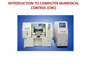
CNC Computer Numerical Control Courtesy of Fives Giddings


- Slides: 52

CNC – Computer Numerical Control Courtesy of Fives Giddings & Lewis Courtesy of EMCO Maier By Arnold Banning 1

CNC machines are programmed using an interpreter that is specified in a publication of the NIST. http: //ws 680. nist. gov/publication/get_pdf. cfm? pub_id=823374 This specification is called RS 274 This spec gives the definitions for the codes used to command axis movement, spindle functions, tool functions, and various machine functions. 2

SPINDLE DIRECTION/START/STOP COMMAND SPINDLE DRIVE COMMUNICATIONS BETWEEN CNC AND PLC CNC STORES PART PROGRAM LOOKS AHEAD IN PGM TO SIGNAL THE PLC CALCULATES MULTIAXIS MOVEMENTS X a x is Y a x is TOOL CHANGER ARM & CHAIN PLC Z a x is BASIC SIMPLE CNC SYSTEM FUNCTIONS ON “G” CODES FOR POSITIONING AND SPEED PALLET CHANGER & CLAMP COOLANT SPINDLE XMSN GEAR RANGE FUNCTIONS ON MISCELANEOUS CODES (M CODES) 3

CNC/Spindle q CNC provides speed command to the spindle drive. q Spindle drive provides power to the motor to run the proper speed q The PLC will control the gear range and commanded direction to the spindle drive. q Spindle encoder reports actual speed and position back to the CNC/Axis Drives q The CNC provides speed command to each of the programmed axes. q The CNC monitors speed and direction by reading the encoder or scale feedback. q The CNC controls the deceleration and stopping of the axes to prevent overshooting the axis at the travel endpoint. CNC/Miscellaneous Functions q Most CNC controls look at least 10 program blocks ahead and prepare codes to be sent to the PLC so it is ready. q For instance, the PLC will be told which tool will be needed next so it can find the tool and have it in the tool changer to be ready as soon as the current tool is finished with it’s work. q The PLC executes commanded pallet changes and pallet locking q The PLC executes coolant on/off q The PLC executes shifting to the proper gear range for the programmed spindle speed 4

CNC controls are used for various automated production machines: Ø Ø Ø Ø Horizontal Mills Vertical/Gantry mills Horizontal Lathes Vertical Lathes Nibblers Plasma and torch cutting machines Brakes & Punches Laser cutters Seat Cover Fabric cutting Grinders Planers Woodworking machines High Pressure water cutting of metals The CNC and PLC can be interfaced with other PLC’s to integrate the CNC machine to conveyors, Pick and Place robots, storage and retrieval systems and any form of automation to provide an accurate and consistent manufacturing operation. 5

So, how do these machines operate? What are some basics mechanically and electrically? We shall take a look in the next few slides. First, how do these machines move? Aren’t they heavy? 6

For linear axes, one surface will have a pocket that hydraulic oil is pumped into at a specific pressure. The oil pressure is adjusted for each pocket so that the moveable part is supported and glides on a thin film of oil. http: //www. zollern. de/en/plain-bearings/hydrostaticbearings. html 7

Many machines move tables, columns, and axes via guide ways and slide bearings. These slide bearings have recirculating bearings that continually move when the axis is in motion. When servicing these machines, never remove a slide bearing without a bar, short piece of way guide or special shipping blank to hold the bearings when the slide is removed. Courtesy of Thompson Industries, Inc. 8

Americanballscrewrepair. com 9

Americanballscrewrepair. com 10

Drive motors may be connected to the ball screw directly by a coupling, or through a gearbox. Gearboxes typically need maintenance as they generally have lubricating oil inside as well as bearings. Courtesy of yamaseiki. com 11

Spindle Cartridge Spindle Info: Collet Key (2) Spindle Bearings Carinteriordesign. net ü Some spindles clamp the tool by a screw that goes into the back of the tool holder. ü The spindle collet keys keep the tool from twisting in the collet. ü Some tools are clamped by fingers that “grab” the back of the tool holder using a drawbar. ü Some spindles require tool holders with a hole in the middle to facilitate thru the spindle coolant. ü Some spindles have bearings that need to be “packed” with grease, and “run in” for a period of time while being monitored for temperature rise, noise, or play. 12

q. Cast iron is the preferred material for machine bases and columns. q. Cast iron is stable, does not warp as much and has better temperature characteristics (usually beefier) q. Fabricated bases and columns are welded sheet metal. q. Fabricated bases are more prone to warp under load, and because of the thinner thickness of the material, are also more sensitive to heat variations. (i. e. welded joints can be hard where the bulk of the surface may be more annealed or softer allowing for size variations and shape distortions. q. Regardless of the frame makeup, a machine tool MUST have a solid foundation and base that often times requires I beams and reinforcement in the concrete. Some machines require foundations varying from a foot to several feet thick depending on the size of the machine. 13

Feedback – “reporting home” SPINDLE DIRECTION/START/STOP COMMAND SPINDLE DRIVE COMMUNICATIONS BETWEEN CNC AND PLC CNC STORES PART PROGRAM LOOKS AHEAD IN PGM TO SIGNAL THE PLC CALCULATES MULTIAXIS MOVEMENTS TOOL CHANGER ARM & CHAIN PLC PALLET CHANGER & CLAMP COOLANT Y X a x i s B Z a x i s SPINDLE XMSN GEAR RANGE The spindle and each axis have an encoder, scale, or other device for speed and position feedback to the CNC. 14

§ In vintage machine tools, the spindle may have a DC tachometer for speed feedback and a resolver for angular position feedback. § It is important for the CNC to know the angular position of the spindle for tool change orientation and for tapping. § Axis motors many times had both a resolver and a tachometer. The tach went to the motor drive and the resolver reported to the CNC for axis position. § Modern digital drives will use the same encoder or scale that the CNC uses for position feedback to tell the motor drive how fast it is moving the axis. § Many times spindle drives were DC shunt type systems. This was so faster spindle speeds could be achieved for smoother or finer finishes on the cuts. Remember a shunt motor can rotate faster than the base speed by weakening or reducing the motor field excitation. § Devices used for position feedback on older machines include Farrand Scales, Accupin Scales, Resolvers, Synchro’s, but more recently, Encoders and Optical Scales are the feedback devices of choice. 15

It may not be obvious to the casual observer, but where the feedback device is located, makes a difference in accuracy and troubleshooting techniques. If all connections are mechanically tight and secure, any method of feedback location is accurate. Encoder Let’s say the picture above is my spindle motor. The encoder is mounted on the tail of the motor. It is attached to the spindle motor shaft by a coupling. The drive end of the motor is attached to the spindle gear box by a coupling. Couplings are a weak link, they can wear, break or sometimes develop some slop or backlash depending on how they are secured to the shaft. If the motor is to run at 1000 RPM and the coupling between the motor and encoder is secure, the encoder will report back to the CNC that the motor is running the proper speed. If the coupling between the motor and the gearbox develops backlash, the finish of the part would suffer because of chatter. If the coupling completely breaks, then the CNC will think the motor is turning 1000 RPM’s, when in reality it is not turning at all. If the spindle encoder was mounted to the spindle shaft itself, this would be a different scenario all together. The encoder would detect no rotation. 16

Axis drives are much the same, only there are more options. Many times for economy’s sake, encoders are placed on the back of the axis motor. Again, the drive end of the motor can be either directly attached to the ball screw or pinion gear for a rack and pinion drive. Encoder In the case of a ball screw, there are couplings at the end of the ball screw, there is the ball nut, and it’s mounting to the axis table or slide. Again, the encoder being on the motor does not alert the CNC to any backlash or physical mis-positioning on the driven side of the motor. Some machines placed the encoder on the end of the ball screw. Here we would eliminate the couplings on the motor shaft and the coupling to the ball screw itself. But the coupling from the ball screw to the encoder or any ball nut problems would not be seen by the CNC. A scale mounted to the machine bed or column with the slider of the scale attached to the ball nut is probably the most reliable and accurate system going. All backlash is between the ball nut and the motor shaft will be detected by the CNC. 17

Before we go too much farther, we need to discuss some of the other fine points of CNC machines. The direction of rotation on the spindle is determined by looking at the rear of the spindle motor. Look at the rotor, and if the rotor is turning CW at the back of the motor, the spindle should also be turning CW. This is true of a lathe also. A mill positions from the centerline of the spindle collet and the face of the spindle nose, not the spindle keys. That is important to remember. When running a CNC machine, if you have a tool in the spindle, you must load the tool length and tool radius offsets, or the machine will try to push the tool through the piece part to the spindle nose. That is called a “wreck”. A lathe positions from the face of the tool turret to the face of the collet. If the machine does not have tool turret, it will position from the face of the tool holder. Remember the lathe turns the piece part and the tool is moved to cut the spinning part. A. 1” cut will reduce the diameter of the piece part by. 2”. Face of spindle nose Centerline of collet Carinteriordesign. net 18

Two Common Types Of Tool Holders (but not the only two) CAT 40 tool holder with knob on back for a drawbar tool clamp. CAT 40 tool holder with internal threads at the back for a screw type tool clamp. Practicalmachinist. com 19

All CNC controls have an operating system. They may differ in features, memory, etc. , but they all follow the NIST RS 274 standard. No, that’s not another communication protocol like RS 232, RS 485, RS 422, etc. It is the “G-Code” language that CNC machines are programmed with. It is a. pdf document, go ahead, download it. It’s good reading. So, we are going to park on this for a little bit and discuss some codes and how they affect the machine. No, this won’t make you a whiz bang CNC programmer in 60 minutes. It is a 5000’ view of what this machine is supposed to do, and how it is commanded to do it. CAM and some CAD software may have plugin’s that will automatically write code for particular types of machines and controls. So, grab a POST and let’s get started. 20

21

Many times a machine may have a pallet or B axis table with a hole in the middle of it. This many times is the actual machine zero point. When the machine has been torn down for repair, it many times will need to be checked for accurate zeroing. The center of this hole sets X 0 and Z 0. Y 0 is the surface of the table. When the machine is first turned “on” it should be referenced. This action is taken in Manual mode generally and will run each axis to a switch. Generally it will make the switch, pull off of the switch and find the next reference pulse on the encoder or scale. In the machine parameters there is a register for each axis in which a dimension is stored. This dimension is displayed on the axis display and represents the distance the machine’s present position is from machine zero, the position shown on the pallet below. A laser or dial indicator may be used to see if the dimensions of the parameter table are still correct. If not, the dimension numbers need to be changed to reflect the correct distance the reference switches are from machine zero. = zero or reference point 22

THE RIGHT HAND RULE FOR DETERMINING AXIS DIRECTIONS 1. Hold your hand with the thumb, forefinger, and middle finger perpendicular to each other. Your thumb represents the X axis Your forefinger represents the Y axis Your middle finger represents the Z axis 2. The direction each finger points represents the positive direction of axis travel. 3. The Z axis is always parallel to the main spindle. The positive direction is normally into the spindle. 4. On a mill, the X axis is generally the axis with the longest travel and is perpendicular to the Z axis. On lathes, the Z axis is the longest axis. 5. Looking into the tip of your middle finger, the forefinger, which is perpendicular to it, represents the Y axis. THE RIGHT HAND RULE FOR DETERMINING AXIS DIRECTIONS CONT’D To determine the clockwise rotary motion of an axis that rotates around the X, Y, or Z axis, close your hand with the thumb sticking out, pointing in the positive direction of the axis you are rotating around. (The thumb may represent X, Y, or Z) The direction of the curl of your fingers is the clockwise or positive rotation of the rotating axis. Rotary axis designations are A, B, and C A rotates around X B rotates around Y C rotates around Z

Y+ 2. 1. 1. 1 Linear Axes A machining center has independent mechanisms for producing relative linear motion of the tool workpiece in three mutually orthogonal directions. These are the X, Y and Z axes. C+ ZA+ 2. 1. 1. 2 Rotational axes Three additional independent mechanisms produce relative Xrotation of the workpiece and the tool around an axis. These mechanisms (often a rotary table on which the workpiece is mounted or a drum on which the spindle is mounted) are called rotational axes and labelled A, B, and C. The A-axis is parallel to the Z+ X-axis. B is parallel to the Y-axis, and C parallel to the Z-axis. Each rotational mechanism may or may not have a mechanical limit on how far it can rotate. RS 274/NGC Interpreter - Version 3 C- AX+ B+ B- Y- 24

NOTE: A “B” Axis is typical on many horizontal machines. However, A and C axes require a drum or some way of moving the spindle. 25

Although the NIST does not specify it, many machines use a % character to indicate the beginning of a part program. Let’s start with some easy things, OK? Any time we write commands in a CNC program we use a “line of code”. Each line is considered a “Block” of the program. So, the line number becomes a Block number. A good programmer may number the blocks by 5’s or 10’s, so that if there is ever a need to edit the program, there are extra unused block numbers that can be inserted without having to renumber the whole cotton picking program. 3. 3 Format of a Line A permissible line of input RS 274/NGC code consists of the following, in order, with the restriction that there is a maximum (currently 256) to the number of characters allowed on a line. 1. an optional block delete character, which is a slash “/”. 2. an optional line number. 3. any number of words, parameter settings, and comments. 4. an end of line marker (carriage return or line feed or both). RS 274/NGC Interpreter - Version 3

N 10 G 00 X 10. 1250 Line Number Word 1 Word 2 Word 1 General Function 00 Rapid Travel Word 2 X axis move From where we are now to X 10. 1250 27

Table of “Word-starting Letters taken from the RS 274 Document. There can be multiple words in a block of program RS 274/NGC Interpreter - Version 3 28

3. 4 Modal Groups Modal commands are arranged in sets called “modal groups”, and only one member of a modal group may be in force at any given time. In general, a modal group contains commands for which it is logically impossible for two members to be in effect at the same time — like measure in inches vs. measure in millimeters. A machining center may be in many modes at the same time, with one mode from each modal group being in effect. The modal groups are shown in Table 4. RS 274/NGC Interpreter - Version 3 29

For several modal groups, when a machining center is ready to accept commands, one member of the group must be in effect. There are default settings for these modal groups. When the machining center is turned on or otherwise re-initialized, the default values are automatically in effect. Group 1, the first group on the table, is a group of G codes for motion. One of these is always in effect. That one is called the current motion mode. It is an error to put a G-code from group 1 and a G-code from group 0 on the same line if both of them use axis words. If an axis word-using G-code from group 1 is implicitly in effect on a line In addition to the above modal groups, there is a group for non-modal G codes: (by having been activated on an earlier line), and a group 0 G-code that uses axis words appears on the line, the activity of the group 1 G-code is suspended for that line. The axis word-using G codes from group 0 are G 10, G 28, G 30, and G 92. RS 274/NGC Interpreter - Version 3 30

3. 5 G Codes G codes of the RS 274/NGC language are shown in Table 5 and described following that. The descriptions contain command prototypes, set in helvetica type. In the command prototypes, three dots (…) stand for a real value. As described earlier, a real value may be (1) an explicit number, 4, for example, (2) an expression, [2+2], for example, (3) a parameter value, #88, for example, or (4) a unary function value, acos[0], for example. In most cases, if axis words (any or all of X…, Y…, Z…, A…, B…, C…) are given, they specify a destination point. Axis numbers are in the currently active coordinate system, unless explicitly described as being in the absolute coordinate system. Where axis words are optional, any omitted axes will have their current value. Any items in the command prototypes not explicitly described as optional are required. It is an error if a required item is omitted. In the prototypes, the values following letters are often given as explicit numbers. Unless stated otherwise, the explicit numbers can be real values. For example, G 10 L 2 could equally well be written G[2*5] L[1+1]. If the value of parameter 100 were 2, G 10 L#100 would also mean the same. Using real values which are not explicit numbers as just shown in the examples is rarely useful. If L… is written in a prototype the “…” will often be referred to as the “L number”. Similarly the “…” in H… may be called the “H number”, and so on for any other letter. RS 274/NGC Interpreter - Version 3 31

List of G codes taken from RS 274/NGC Interpreter - Version 3 32

3. 6 Input M Codes M codes of the RS 274/NGC language are shown in Table 7. RS 274/NGC Interpreter - Version 3 33

3. 6. 1 Program Stopping and Ending — M 0, M 1, M 2, M 30, M 60 To stop a running program temporarily (regardless of the setting of the optional stop switch), program M 0. To stop a running program temporarily (but only if the optional stop switch is on), program M 1. It is OK to program M 0 and M 1 in MDI mode, but the effect will probably not be noticeable, because normal behavior in MDI mode is to stop after each line of input, anyway. To exchange pallet shuttles and then stop a running program temporarily (regardless of the setting of the optional stop switch), program M 60. If a program is stopped by an M 0, M 1, or M 60, pressing the cycle start button will restart the program at the following line. To end a program, program M 2. To exchange pallet shuttles and then end a program, program M 30. Both of these commands have the following effects. 1. Axis offsets are set to zero (like G 92. 2) and origin offsets are set to the default (like G 54). 2. Selected plane is set to CANON_PLANE_XY (like G 17). 3. Distance mode is set to MODE_ABSOLUTE (like G 90). 4. Feed rate mode is set to UNITS_PER_MINUTE (like G 94). 5. Feed and speed overrides are set to ON (like M 48). 6. Cutter compensation is turned off (like G 40). 7. The spindle is stopped (like M 5). 8. The current motion mode is set to G_1 (like G 1). 9. Coolant is turned off (like M 9). No more lines of code in an RS 274/NGC file will be executed after the M 2 or M 30 command is executed. Pressing cycle start will start the program back at the beginning of the file. RS 274/NGC Interpreter - Version 3 34

3. 6. 2 Spindle Control — M 3, M 4, M 5 To start the spindle turning clockwise at the currently programmed speed, program M 3. To start the spindle turning counterclockwise at the currently programmed speed, program M 4. To stop the spindle from turning, program M 5. It is OK to use M 3 or M 4 if the spindle speed is set to zero. If this is done (or if the speed override switch is enabled and set to zero), the spindle will not start turning. If, later, the spindle speed is set above zero (or the override switch is turned up), the spindle will start turning. It is OK to use M 3 or M 4 when the spindle is already turning or to use M 5 when the spindle is already stopped. RS 274/NGC Interpreter - Version 3 35

3. 6. 3 Tool Change — M 6 To change a tool in the spindle from the tool currently in the spindle to the tool most recently selected (using a T word — see Section 3. 7. 3), program M 6. When the tool change is complete: • The spindle will be stopped. • The tool that was selected (by a T word on the same line or on any line after the previous tool change) will be in the spindle. The T number is an integer giving the changer slot of the tool (not its id). • If the selected tool was not in the spindle before the tool change, the tool that was in the spindle (if there was one) will be in its changer slot. • The coordinate axes will be stopped in the same absolute position they were in before the tool change (but the spindle may be re-oriented). • No other changes will be made. For example, coolant will continue to flow during the tool change unless it has been turned off by an M 9. The tool change may include axis motion while it is in progress. It is OK (but not useful) to program a change to the tool already in the spindle. It is OK if there is no tool in the selected slot; in that case, the spindle will be empty after the tool change. If slot zero was last selected, there will definitely be no tool in the spindle after a tool change. RS 274/NGC Interpreter - Version 3 36

3. 6. 4 Coolant Control — M 7, M 8, M 9 To turn mist coolant on, program M 7. To turn flood coolant on, program M 8. To turn all coolant off, program M 9. It is always OK to use any of these commands, regardless of what coolant is on or off. 3. 6. 5 Override Control — M 48 and M 49 To enable the speed and feed override switches, program M 48. To disable both switches, program M 49. See Section 2. 2. 1 for more details. It is OK to enable or disable the switches when they are already enabled or disabled. RS 274/NGC Interpreter - Version 3 37

3. 7 Other Input Codes 3. 7. 1 Set Feed Rate — F To set the feed rate, program F…. The application of the feed rate is as described in Section 2. 1. 2. 5, unless inverse time feed rate mode is in effect, in which case the feed rate is as described in Section 3. 5. 19. 3. 7. 2 Set Spindle Speed — S To set the speed in revolutions per minute (rpm) of the spindle, program S…. The spindle will turn at that speed when it has been programmed to start turning. It is OK to program an S word whether the spindle is turning or not. If the speed override switch is enabled and not set at 100%, the speed will be different from what is programmed. It is OK to program S 0; the spindle will not turn if that is done. It is an error if: • the S number is negative. As described in Section 3. 5. 16. 5, if a G 84 (tapping) canned cycle is active and the feed and speed override switches are enabled, the one set at the lower setting will take effect. The speed and feed rates will still be synchronized. In this case, the speed may differ from what is programmed, even if the speed override switch is set at 100%. RS 274/NGC Interpreter - Version 3 38

3. 7. 3 Select Tool — T To select a tool, program T…, where the T number is the carousel slot for the tool. The tool is not changed until an M 6 is programmed (see Section 3. 6. 3). The T word may appear on the same line as the M 6 or on a previous line. It is OK, but normally useful, if T words appear on two or more lines with no tool change. The carousel may move a lot, but only the most recent T word will take effect at the next tool change. It is OK to program T 0; no tool will be selected. This is useful if you want the spindle to be empty after a tool change. It is an error if: • a negative T number is used, • a T number larger than the number of slots in the carousel is used. On some machines, the carousel will move when a T word is programmed, at the same time machining is occurring. On such machines, programming the T word several lines before a tool change will save time. A common programming practice for such machines is to put the T word for the next tool to be used on the line after a tool change. This maximizes the time available for the carousel to move. RS 274/NGC Interpreter - Version 3 39

3. 8 Order of Execution The order of execution of items on a line is critical to safe and effective machine operation. Items are executed in the order shown in Table 8 if they occur on the same line. RS 274/NGC Interpreter - Version 3 40

3. 5. 10 Cutter Radius Compensation — G 40, G 41, and G 42 To turn cutter radius compensation off, program G 40. It is OK to turn compensation off when it is already off. Cutter radius compensation may be performed only if the XY-plane is active. To turn cutter radius compensation on left (i. e. , the cutter stays to the left of the programmed path when the tool radius is positive), program G 41 D…. To turn cutter radius compensation on right (i. e. , the cutter stays to the right of the programmed path when the tool radius is positive), program G 42 D…. The D word is optional; if there is no D word, the radius of the tool currently in the spindle will be used. If used, the D number should normally be the slot number of the tool in the spindle, although this is not required. It is OK for the D number to be zero; a radius value of zero will be used. It is an error if: • the D number is not an integer, is negative or is larger than the number of carousel slots, • the XY-plane is not active, • cutter radius compensation is commanded to turn on when it is already on. The behavior of the machining center when cutter radius compensation is described in Appendix B. RS 274/NGC Interpreter - Version 3 41

Appendix B. Cutter Radius Compensation B. 1 Introduction The cutter radius compensation 1 capabilities of the Interpreter enable the programmer to specify that a cutter should travel to the right or left of an open or closed contour in the XY-plane composed of arcs of circles and straight line segments. Cutter radius compensation is performed only with the XY-plane active. All the figures in this appendix, therefore, show projections on the XY-plane. Where the adjacent sides of remaining material meet at a corner, there are two common ways to handle the tool path. The tool may pass in an arc around the corner, or the tool path may continue straight in the direction it was going along the first side until it reaches a point where it changes direction to go straight along the second side. Figure 2 shows these two types of path. On Figure 2: • Uncut material is shaded in the figures. Note that the inner triangles have the same shape with both tool paths. • The white areas are the areas cleared by the tool. • The lines in the center of the white areas represent the path of the tip of a cutting tool. • The tool is the cross-hatched circles. RS 274/NGC Interpreter - Version 3 42

Both paths will clear away material near the shaded triangle and leave the shaded triangle uncut. When the Interpreter performs cutter radius compensation, the tool path is rounded at the corners, as shown on the left in Figure 2. In the method on the right (the one not used), the tool does not stay in contact with the shaded triangle at sharp corners, and more material than necessary is removed. There also two alternatives for the path that is programmed in NC code during cutter radius compensation. The programmed path may be either (1) the edge of the material to remain uncut (for example, the edge of the inner triangle on the left of Figure 2), or (2) the nominal tool path (for example, the tool path on the left side of Figure 2). The nominal tool path is the path that would be used if the tool were exactly the intended size. The Interpreter will handle both cases without being told which one it is. The two cases are very similar, but different enough that they are described in separate sections of this manual. To use the material edge method, read Appendix B. 3. To use the nominal path method, read Appendix B. 4. RS 274/NGC Interpreter - Version 3 43

RS 274/NGC Interpreter - Version 3 44

Z-axis motion may take place while the contour is being followed in the XY-plane. Portions of the contour may be skipped by retracting the Z-axis above the part, following the contour to the next point at which machining should be done, and re-extending the Z-axis. These skip motions may be performed at feed rate (G 1) or at traverse rate (G 0). The Z motion will not interfere with the XY path following. The sample NC code in this appendix does not include moving the Z-axis. In actual programs, include Z-axis motion wherever you want it. Rotational axis motions (A, B, and C axes) are allowed with cutter radius compensation, but using them would be very unusual. Inverse time feed rate (G 93) or units per minute feed rate (G 94) may be used with cutter radius compensation. Under G 94, the feed rate will apply to the actual path of the cutter tip, not to the programmed contour. RS 274/NGC Interpreter - Version 3 45

B. 2 Programming Instructions B. 2. 1 Turning Cutter Radius Compensation On To start cutter radius compensation keeping the tool to the left of the contour, program G 41 D…. The D word is optional (see “Use of D Number”, just below). To start cutter radius compensation keeping the tool to the right of the contour, program G 42 D… In Figure 2, for example, if G 41 were programmed, the tool would move clockwise around the triangle, so that the tool is always to the left of the triangle when facing in the direction of travel. If G 42 were programmed, the tool would stay right of the triangle and move counterclockwise around the triangle. B. 2. 2 Turning Cutter Radius Compensation Off To stop cutter radius compensation, program G 40. It is OK to turn compensation off when it is already off. RS 274/NGC Interpreter - Version 3 46

B. 2. 3 Sequencing If G 40, G 41, or G 42 is programmed on the same line as tool motion, cutter compensation will be turned on or off before the motion is made. To make the motion come first, the motion must be programmed on a separate, previous line of code. B. 2. 4 Use of D Number Programming a D word with G 41 or G 42, is optional. If a D number is programmed, it must be a non-negative integer. It represents the slot number of the tool whose radius (half the diameter given in the tool table) will be used, or it may be zero (which is not a slot number). If it is zero, the value of the radius will also be zero. Any slot in the tool table may be selected. The D number does not have to be the same as the slot number of the tool in the spindle, although it is rarely useful for it not to be. If a D number is not programmed, the slot number of the tool in the spindle will be used as the D number. B. 3 Material Edge Contour When the contour is the edge of the material, the outline of the edge is described in the NC program. For a material edge contour, the value for the diameter in the tool table is the actual value of the diameter of the tool. The value in the table must be positive. The NC code for a material edge contour is the same regardless of the (actual or intended) diameter of the tool. RS 274/NGC Interpreter - Version 3 47

B. 3. 1 Programming Entry Moves In general, two pre-entry moves and one entry move are needed to begin compensation correctly. However, if there is a convex corner on the contour, a simpler method is available using zero or one pre-entry move and one entry move. The general method, which will work in all situations, is described first. We assume here that the programmer knows what the contour is already and has the job of adding entry moves. B. 3. 1. 1 General Method The general method includes programming two pre-entry moves and one entry move. See Figure 3. The shaded area is the remaining material. It has no corners, so the simple method cannot be used. The dotted line is the programmed path. The solid line is the actual path of the tool tip. Both paths go clockwise around the remaining material. A cutter one unit in diameter is shown part way around the path. The black dots mark points at the beginning or end of programmed or actual moves. The figure shows the second pre-entry move but not the first, since the beginning point of the first preentry move could be anywhere. RS 274/NGC Interpreter - Version 3 48

First, pick a point A on the contour where it is convenient to attach an entry arc. Specify an arc outside the contour which begins at a point B and ends at A tangent to the contour (and going in the same direction as it is planned to go around the contour). The radius of the arc should be larger than half the diameter given in the tool table. Then extend a line tangent to the arc from B to some point C, located so that the line BC is more than one tool radius long. After the construction is finished, the code is written in the reverse order from the construction. The NC code is shown in Table 12; the first three lines are the entry moves just described. RS 274/NGC Interpreter - Version 3 49

Cutter radius compensation is turned on after the first pre-entry move and before the second preentry move (including G 41 on the same line as the second pre-entry move turns compensation on before the move is made). In the code above, line N 0010 is the first pre-entry move, line N 0020 turns compensation on and makes the second preentry move, and line N 0030 makes the entry move. RS 274/NGC Interpreter - Version 3 50

3. 5. 11 Tool Length Offsets — G 43 and G 49 To use a tool length offset, program G 43 H…, where the H number is the desired index in the tool table. It is expected that all entries in this table will be positive. The H number should be, but does not have to be, the same as the slot number of the tool currently in the spindle. It is OK for the H number to be zero; an offset value of zero will be used. It is an error if: • the H number is not an integer, is negative, or is larger than the number of carousel slots. To use no tool length offset, program G 49. It is OK to program using the same offset already in use. It is also OK to program using no tool length offset if none is currently being used. RS 274/NGC Interpreter - Version 3 51

Most programs are written in Absolute mode. However, you may encounter programs written in Incremental where each move is a specified as the axis and distance from where the spindle is setting. The next incremental move is specified the same way. RS 274/NGC Interpreter - Version 3 52
 Testamento de freddie mercury
 Gsk 980 tdc manual pdf
 Courtesy notice
 Courtesy award
 Clarity and completeness
 Concreteness
 Courtesy is a positive trait
 Courtesy speeches
 Respect attitude
 7 cs of effective communication
 Crumbing down is a task carried out
 Military courtesy definition
 Greetings and farewells in english and spanish
 Greetings farewells and courtesy expressions en español
 Legal profession complaints committee v in de braekt
 Courtesy formulas
 Courtesy formulas
 Courtesy
 Courtesy
 Courtesy
 Umlsec
 Slide courtesy
 Empirical formula with percentages
 Abacbn
 Slide courtesy
 Coe 202
 Safteng
 Courtesy
 Cnc torna
 Tool holding devices in lathe
 Pacaembucnc
 Haas macro list
 G kodovi za cnc strug
 Makesmith cnc
 Cnc alapismeretek
 Cnc programiranje primeri
 G76 p hesaplama
 Apt programming examples
 G28 cnc code
 G-code simulator
 Cnc feladatok megoldással
 Cnc sexualidad
 Constructional features of cnc machines
 Feedback devices in cnc
 Part programming format
 Constructional features of cnc machines
 Foo joon liang
 Cnc programming tips
 Swansoft cnc simulator
 Eksantrik pres risk analizi
 Linearna interpolacija
 Cnc m kódok
 Gcode
Gcode

