CNC Turning Module 2 Introduction to MTS Top


.")


 {Every time click")


: ØWorkpiece length: 64 mm ØWorkpiece diameter: 35")


")


: ØWorkpiece length: 60 mm ØWorkpiece diameter: 32")


: Ø Workpiece length: 40 mm Ø Workpiece diameter:")

- Slides: 114
CNC Turning Module 2: Introduction to MTS Top. Turn and G & M codes
Watch the following video
Module objectives • 1. Demonstrate familiarity with the MTS Simulator. • 2. Create a setup sheet. • 3. Identify the different parts that compose the NC program. • 4. Identify the difference between rapid positioning and feed rate positioning. • 4. Utilize both G-codes and M-codes. • 5. Demonstrate the ability to write a simple NC part program.
CNC Machine Simulator: A simulator is used to create NC programs, simulating them and checking their quality. These programs can be transferred and executed on the real CNC machine to produce the work part. The simulator that we are going to deal with throughout the term is called the MTS Simulator.
MTS simulator software:
How to start the software? To start the MTS simulator: ØClick on windows “start” button in the task bar. ØPoint on “all programs”. ØPoint on “MTS Top. CAM 7. 4”. ØClick on “TOPCAM”. ØOr click on the “MTS Top. CAM” shortcut on the desktop.
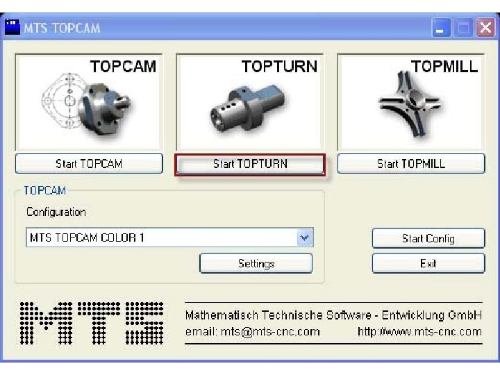
How to start the software? The start-up menu shown in Fig. 2. 1 will offer you the following software modules for selection: TOPCAM, TOPTURN and TOPMILL. TOPTURN is used for turning programming. However, TOPMILL is used for milling programming. As Turning is introduced in this course so you will choose TOPTURN to start turning.
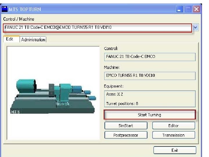
How to start the software? The next window that appears is to select the controller. The controller is the link between the software (NC program) and the hardware (CNC machine). From the controllers list, choose the “FANUC 21 TB Code-C EMCO@EMCO TURN 55 R 1 T 8 VDI 10” since it is the one used by the EMCO CNC Turning Machine available in the lab, then click on “start turning” as shown in Fig. 2. 2.
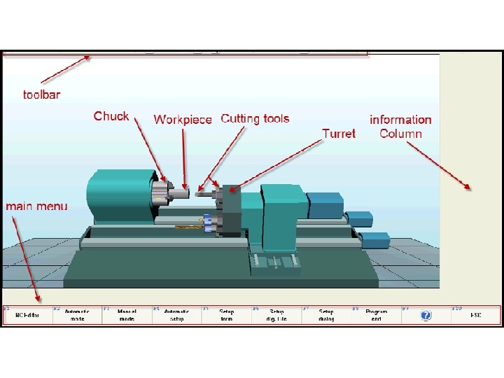
How to start the software? MTS TOPTURN simulator will start. The main areas of the screen are shown on Fig. 2. 3.
How to change your display
How to change the display? You have two main ways to display the simulator Graphic display Modes Display mode Icons
Setup Sheet
How to create a setup sheet In order to set the machine, a setup sheet is created. The setup means to enter the information of the tools, workpiece dimensions, material used, holding devices and the position of zero point.
Example 1 Prepare a “Setup sheet” with the following information: Ø Workpiece length: 60 mm Ø Workpiece diameter: 40 mm Ø Workpiece material: Aluminum/Almg 1 Ø The chucking depth: 14 mm (Chucking depth is the length of the Ø workpiece that inserted into the chuck) Ø Workpart zero location: “Right side – center of the workpart surface Ø Tool position: position 4 (The turret of the machine can hold many Ø tools, so this is the position of the tool on the turret. ) Ø Tool to be used: Ø Tool type: Corner Tool Left, Ø Tool Name: CCMT 060202_SCACR 0808 B 06_B 3. 10 1213.
1. Click “Setup dlg. File” or “F 6”. On the main menu.
2. Write the File name: The file name is “Setup 1”, then click “Open” as shown below
3. Click on tab 1: “General information” and then enter the “program number” starting with “O” letter. In this example you can write “O 1”.
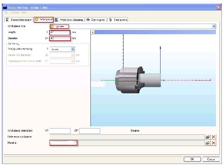
4. Click on tab 2: “Workpiece”, the “Workpiece type” list box, the cylinder is the default. Click the list box arrow to see the different shapes available in the software then select. “Cylinder” for the workpiece type. The next step is to fill in the information for the length, Diameter, and material type. a. Length L: “ 60” b. Diameter D: “ 40” c. For material selection click on the folder in the field of “Material”
d. Select “Non ferrous folder” or click on the green “N” to select the required material as shown below
e. Click on “Aluminum folder”. Figure below
f. Click on “Almg 1”, then Click quit. Figure below select and
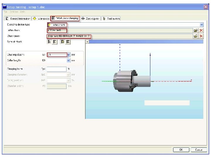
5. Click on tab 3: “Workpiece clamping” to fill in the clamping device information as shown in Figure below ØClamping device type: “Lathe chuck” ØLathe chuck: “KSF 74 – 3 As. B” (depend on the type and size of the workpiece) Ø Chuck jaws: Step jawHB 3–B 09 x L 14_7_4 x. H 20_14_7 (depend on the type and size of the workpiece) ØChucking depth: “ 14”
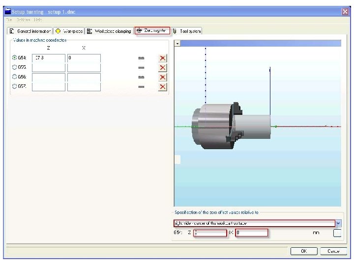
6. Click on tab 4: “Zero register” to fill in the information related to the workpiece Zero point as shown in Figure below Specification of zero offset value relative to: Ø “Right side – center of the workpart surface” Ø G 54 Z: “ 0” X: ” 0”
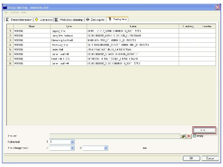
7. Click on tab 5: “Tool system” in order to select the tools that will be used in the program. 8. Click “Edit” as shown in Figure below for tool selection.
a. From the drop down menu “File” to open a new file as shown in Figure below
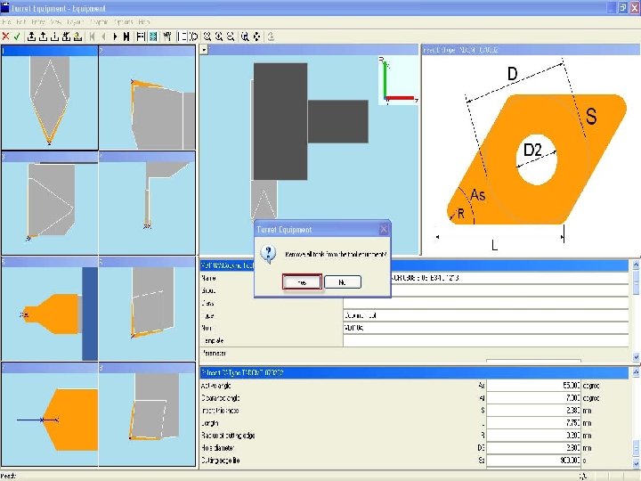
b. A message appears asking the following question “Remove all tools from the tool equipment? ” , Select “yes” if you want to select a new tool set as shown in Figure below.
c. Double click on position 4 as the selected tool should be placed in position No. 4 as shown in Figure below
d. Double click on ”Corner tool left” to select the type of the tool mentioned in the setup sheet as shown in Figure below
e. Click on the correct tool name “CCMT 060202_SCACR 0808 B 06_B 3. 10 1213”, then, save it by clicking. The right column under the tool name shows the properties and dimensions of the tool as shown in Figure below
f. Click “Save and quit”. Figure below
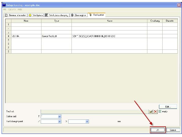
9. Click “OK” to end the setup as shown in Figure below
Check and edit the setup sheet
Check and edit the setup sheet To check the prepared setup sheet, click on “editor” Or press “F 4” or select “NC editor from the main menu”
Click “Accept Quit” from the editor menu at the bottom.
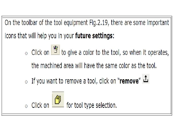
On the main screen try the following icons which allow you to edit the tool equipment: Ø Click on “setup mode” to activate the tool equipment icon. Ø Setup mode is used to make the machine setup (clamping Ø devices, tools … etc). Ø Click on “tool equipment” to see the tools mounted on the turret. Ø Click on “quit” to exit from the tool equipment. Ø On the bottom menu press “Esc” or “F 10” to return to the main menu.
Ø Click “Esc” or “F 10” ØClick “Yes” ØOpen the MTS again as explained earlier, (Click Start Turning) ØTo open your setup again click on “Open NC Program” Ø(Open NC Program is to open new or existing NC program) ØSelect “setup 1” then click “open” ØClick on “editor” twice to see your setup again. ØPress “Accept Quit” from the editor menu at the bottom. ØOn the bottom menu press “Esc” or “F 10” to return to the main menu. ØClick “Esc” or “F 10”.
Practical Task 1 Page 18
Practical Task 1 : Use MTS software to do the following setup. Give your setup the name “Example 2” Setup sheet” information (Parameters): Ø Workpiece length: 67 mm Ø Workpiece diameter: 40 mm Ø Workpiece material: BrassCu. Zn 30 Ø The chucking depth: 14 mm Ø Workpiece zero location: “Right side – center of the workpart Ø surface” Ø Tool position: position 6 Ø Tool to be used: Ø Tool type: Corner Tool Left, Ø Tool Name: CCMT 060204_SCGCR 0808 B 06_B 3 -10 1213
Basics of CNC programming
Basics of CNC programming A programmer writes a set of instructions describing how he or she would like the machine to move and then feeds the program into the machine’s computer which is called the controller. The computer reads the instructions and sends electrical signals to a motor, which then turns a screw to move the machine. A sensor mounted on the machine sends positioning information back to the computer.
Basics of CNC programming CNC machine tools produce only the movements that are described in a part program (a program that describes the machining operations and dimensions). Therefore, a programmer must write a part program in a language that the controller can understand. The most popular language for NC programming is G & M programming codes. One of the popular controller manufacturers using standard G & M codes is Fanuc.
Structure of a NC Program:
Structure of a NC Program:
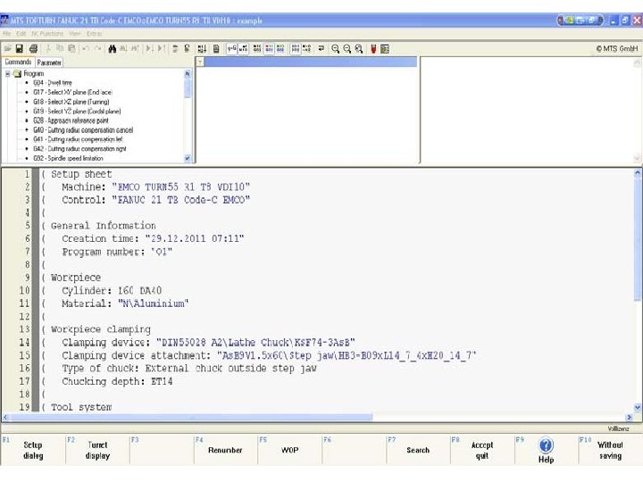
Structure of a NC Program: The NC program consists of a series of commands with which the CNC machine tool is instructed to manufacture a certain work part. The first line in the NC Program contains the program name. The NC program names can contain alphanumerical (containing letters and numbers) or numerical characters.
Structure of a NC Program: Program core: Consists of a sequence of blocks (Lines). Each block contains the technical and geometric information that the controller requires for the correspondent machining step. It starts always with the block Number (N) e. g. N 10, then the instructions or commands follow.
Structure of a NC Program: Example of one block diagram N 10 G 0 X 30 Z 20 Where G 0 is a G code command (X 30 Z 20) are the co-ordinates of the target point.
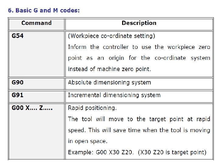
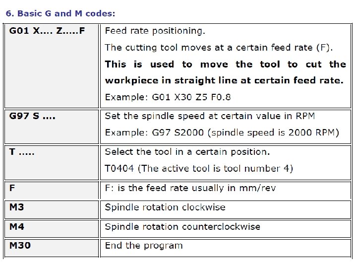
Structure of a NC Program: Program End: Program end: Consists of one block having one command. The following table contains few basic G-codes, plus some additional and Miscellaneous functions (M-codes). .
Structure of a NC block:
Basic G and M Codes
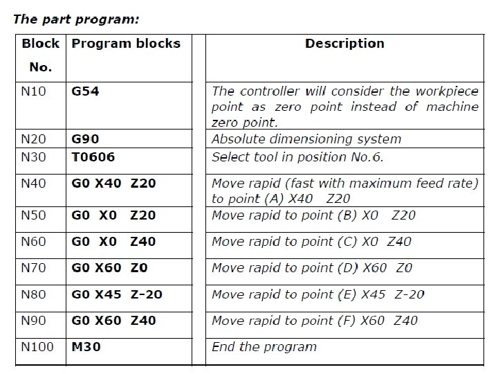
Example Open the prepared setup sheet “Example 2”. In the “editor” write the given NC part program using absolute dimensioning mode, to move the cutting tool in rapid positioning to the points shown below from (A) to (F) as in the figure
Example
Solution 1. Click: Open NC Program 2. Select “example 2” 3. From the above menu Click “Interactive mode” (Interactive mode is the simulating mode in which you can write, edit and simulate you program. )
Solution 4. Write the program as follows: G 54 (Enter ) {Every time click (Enter ) again or (Y) to accept what you entered or if there is a mistake click (N) to be able to edit line}.
Solution Ø Ø Ø Ø Ø G 90 T 0606 ATM-422 – CNC Turning G 0 X 40 Z 20 (Select 2 D-Graphic display mode. ) G 0 X 0 Z 20 G 0 X 0 Z 40 G 0 X 60 Z 0 G 0 X 45 Z-20 G 0 X 60 Z 40 M 30
MTS modes of simulation
MTS modes of simulation The following icons allow you to simulate the above program in different modes:
MTS modes of simulation a. Automatic mode: to run an NC program automatically.
MTS modes of simulation b. Single block mode: to run an NC program block by block where the operator need to confirm the execution of each block by click enter.
MTS modes of simulation c. Interactive mode: to run an NC program block by block with the possibility to edit the executed block if not confirmed with the needed operation.
MTS modes of simulation d. Pause the simulation
MTS modes of simulation e. Stop: To stop the simulation at any step while running the program.
MTS modes of simulation f. Test run: The test run option is used to simulate the program very fast to reach a certain step in the program. However, the simulation speed while using the test run option has nothing to do with the real machining of the workpiece.
Practical Task 2 Page 23
Practical Task 2 Run the program “Example 2” in the different modes of simulation available in the MTS software. Ø Run the program using “automatic mode” (click on “pause” then resume simulation while running).
Practical Task 2 Ø Run the program using “single block mode” (click on “test run” while running)
Practical Task 2 ØClick on “editor” : On the editor you can write and edit your program and from the toolbar of the editor you can copy, paste, cut and do many tasks.
Practical Task 2 Ø From the menu bar click on “NC Functions”.
Practical Task 2 Ø Click on “Block Numbering” from the drop menu
Practical Task 2 Change the start block number and the step size, then click “Ok”. This will change your blocks’ numbers.
Practical Task 3 Page 24
Practical Task 3 Prepare a setup sheet with the following information and write NC program using absolute dimensioning, to move the tool in rapid positioning to the points (From A to F), shown on the drawing in the figure below:
Practical Task 3 Setup sheet” information (parameters): ØWorkpiece length: 64 mm ØWorkpiece diameter: 35 mm ØWorkpiece material: Aluminium/Almg 1. ØWorkpiece zero location: “Right side – center of the workpart surface” ØThe chucking depth: 14 mm ØTool position: position 8 ØTool to be used: ØTool type: Corner Tool Left, ØTool Name: CCMT 060202_SCACR 0808 B 06_B 3. 10 1213
Practical Task 3
Example 3 Page 26
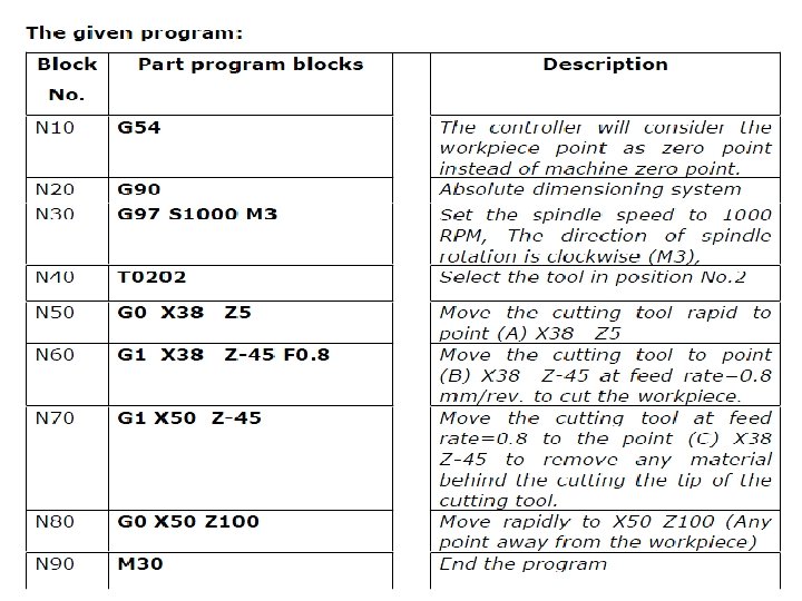
Example 3 Prepare a setup sheet with the following information then write the NC program given below using absolute dimensioning, to move the tool in feed rate positioning to the points shown on the drawing in the figure below:
Example 3 “Setup sheet” information: Ø Workpiece length: 70 mm Ø Workpiece diameter: 40 mm Ø Workpiece material: Aluminum/Almg 1 Ø The chucking depth: 14 mm Ø Workpiece zero location: “Right side – center of the workpart surface” Ø Tool position: position 2 Ø Tool to be used: Ø Tool type: Corner Tool Left, Ø Tool Name: VBMT 110302_SVJCR 0808 C 06_B 3 -10 1213
Example 3
Example 3 Solution The program “Example 3” already open • Open NC program • o Choose “Example 3” • o Click “open”
Example 3 Solution • Run the program using “single block mode” (click on “test run” while running) • o Run the program using “interactive mode” (switch • between “ 2 D graphic” , “ 3 D graphic” or “ 3 D graphic (part)” while running). • o You can click “stop” at any step while running the program.
Example 3 Solution • Run the program using “single block mode” (click on “test run” while running)
Example 3 Solution • Run the program using “interactive mode” (switch between “ 2 D graphic” “ 3 D graphic” or “ 3 D graphic (part)” while running).
Example 3 Solution • You can click “stop” at any step while running the program. • Use the zoom icons to view specific areas.
Dimensioning
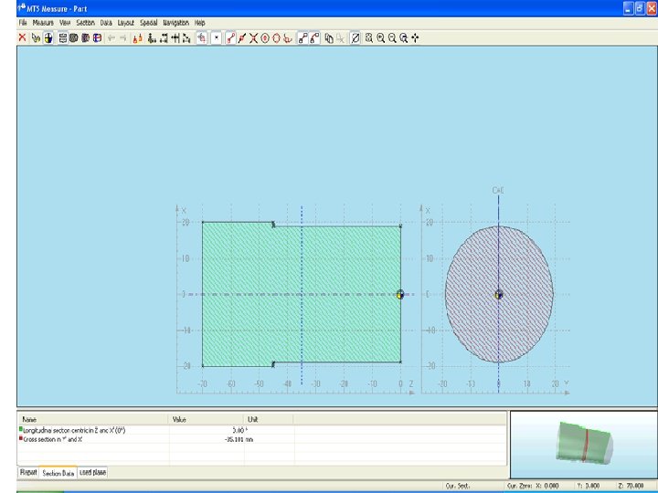
Example 3 Solution • On the toolbar, click on “Dimensioning” • Explore icons to check the dimensions of the work part.
Example 3 Solution The dimensioning screen allows you to check the dimensions of your work part. The default view gives you two section views from the workpiece. The following are some important tools:
Example 3 Solution Move current section: By picking this icon and drag the selection line.
Example 3 Solution measure points: activate and deactivate the measure points view (ON/OFF)
Example 3 Solution Display points: each icon display a certain points on the screen. (this is compared to Object snap setting in Auto. CAD).
Example 3 Solution a. Contour points b. Middle line point c. Intersection point d. Circle center e. Quadrant points f. Middle arc to deactivate any icon, just double click on it.
Example 3 Solution Point to point measurement: Allow you to take measurements from one point to another.
Practical Task 4 Page 31
Practical Task 4 Prepare a setup sheet with the following information then write NC program using absolute dimensioning, to move the tool in feed rate positioning as shown on the drawing. Figure below
Practical Task 4 “Setup sheet” information (parameters): ØWorkpiece length: 60 mm ØWorkpiece diameter: 32 mm ØWorkpiece material: Aluminium/Almg 1 ØThe chucking depth: 14 mm ØWorkpiece zero location: “Right side – center of the workpart surface” ØTool position: position 8 ØTool to be used: ØTool type: Corner Tool Left, ØTool Name: VBMT 110302_SVJCR 0808 C 06_B 3 -10 1213
Example 4 Page 32
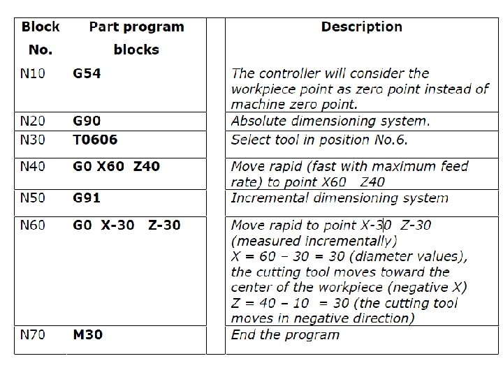
Example 4 Prepare a setup sheet with the following information then write the NC program given below using incremental mode to move the tool in rapid positioning from point A to B as shown on the drawing
Example 4 “Setup sheet” information (parameters): Ø Workpiece length: 40 mm Ø Workpiece diameter: 30 mm Ø Workpiece material: BrassCu. Zn 30 Ø The chucking depth: 14 mm Ø Workpiece zero location: “Right side – center of the workpart surface” Ø Tool position: position 6 Ø Tool to be used: Ø Tool type: Corner Tool Left, Ø Tool Name: CCMT 060202_SCACR 0808 B 06_B 3. 10 1213
Don’t forget to solve your homework