Classical Molecular Dynamics CEC Inha University ChiOk Hwang


- Slides: 21

Classical Molecular Dynamics CEC, Inha University Chi-Ok Hwang

Perspectives • Empirical methods - classical molecular dynamics - tight-binding methods • First-principles methods - tight-binding methods - density-functional theory - exact methods; quantum MC

Molecular Dynamics: General • Solving classical equations of motion for a system of N molecules interacting via a potential V V ≈ Σ V 1(ri) + Σ Σ Veff 2(rij) • Lennard-Jones 12 -6 potential V IJ(r)= 4ε ((σ/r)12 -(σ/r)6)

Molecular Dynamics: General • Algorithms 1: Verlet algorithm r(t+δt)=r(t) + δtv(t)+1/2 (δt)2 a(t) (1) r(t-δt)=r(t) - δtv(t)+1/2 (δt)2 a(t) (2) from the above two equations, we get r(t+δt)= 2 r(t) - r(t-δt) + (δt)2 a(t) v(t) = (r(t+δt) - r(t-δt))/(2δt)

Molecular Dynamics: General • Algorithms 2: Leap-Frog algorithm r(t+δt)=r(t) + δt v(t+δt/2) = v(t-δt/2) + δt a(t); update first • Algorithms 3: Velocity Verlet algorithm r(t+δt)= r(t) + δt v(t) + (δt)2/2 a(t) v(t+δt) = v(t) + δt (a(t) + a(t+δt))/2

Molecular Dynamics: General • Periodic boundary conditions 1) for( i=1; i <= Cell_N_x; i++){ Cell_P[i] = i+1; Cell_M[i] = i-1; } Cell_P[Cell_N_x] = 1; Cell_M[1] = Cell_N_x; 2) while( (*xnew) < 0 ){ *xnew = *xnew + Sx; }

Molecular Dynamics: General • Potential truncation • Cell method: linked list and non-overlapping nearby cell sweeping • Thermodynamic quantities - kinetic temperature

Molecular Dynamics: General - pressure

Molecular Dynamics: General • Mean square displacement: Einstein relation • radial distribution function g(r) • Green-Kubo relation

Ion Implantation • Simulation size: cascade size (10 -25 cm 3 (M. -J. Caturla etc, PRB 54, 16683, 1996) ) - 1000 atoms (J. B. Gibson etc, PR 120(4), 1229, 1960) - a few hundreds of thousands of atoms (J. Frantz etc, PRB 64, 125313 , 2001) • Time scales - thermal vibration periods of atoms in solids: 0. 1 ps (10 -13 sec) or longer - cascade lifetime: 10 ps (M. -J. Caturla etc, PRB 54, 16683, 1996) • Si density: 5 x 10²² /cm 3 (5. 43Å unit cell, 8/unit cell) • ion dose: 1017 ions/cm 2

Ion Implantation • ion implantation Potential: BCA - nuclear stopping power; elastic collision Vij(r) = Zi Zje 2 /r Φ(r); screening of the nuclei due to the electron cloud ① Thomas-Fermi ② ZBL; universal screening potential - electronic stopping power; frictional force ③ Stillinger-Weber potential

Ion Implantation • Simulations of ion implantation - Full MD - Recoil Interaction Approximation (RIA) (1 -100 ke. V) - BCA: valid for low-mass ions at incident energies from 1 -15 ke. V (M. -J. Caturla, etc, PRB 54, 16683, 1996)

Ion Implantation Three phases of collision cascade - collisional phase (0. 1 -1 ps) - thermal spike (1 ns) - relaxation phase (a few thousands of fs) • Measurements of depth profiling - Rutherford Backscattering Spectroscopy (RBS) - Secondary Ion Mass Spectroscopy (SIMS) - (Energy-Filtered) Transmission Electron Microscopy ((EF)TEM) •

MDRANGE • Calculating range profiles of ions implanted into crystalline materials as a histogram of the maximum penetration depths of 10, 000 -20, 000 ions • Modification of full MD MOLDY code • Recoil interaction approximation (RIA) - considering only interactions between the recoil ion and its nearest neighbors within a certain distance - better than BCA but about ten times slower than BCA • 0. 1 -100 ke. V energy range: one fourth of the interatomic distance difference in the mean range about 300 e. V

MDRANGE • nuclear stopping power - ZBL-type as default - Mazzone (Morse+harmonic well) for tetrahedral semiconductors in initial state calculation - Morse-type potential for metals in initial state calculation • Electronic stopping power models - Non-local electronic stopping power read in from input file - Puska-Echenique-Nieminen-Richie (PENR) model (MDRANGE 3. 0) - Brandt-Kitakawa (BK) model (MDRANGE 3. 0)

MDRANGE • Dose range: • Damage build-up modeling (2002) - Amorphization level is proportional to the nuclear deposited energy in that depth region - Electronic stopping ① point-like ion and a spherically symmetric electron distribution ② maximum distance of the charge distribution of Si, 1. 47 Å - Using 20 predamaged boxes

MDRANGE • Time step Δtmin = min( kt /v, Et /Fv, 1. 1 Δtold ) - kt, Et are proportional constants - inversely proportional to the recoil velocity - inversely proportional to the product of the total force F the recoil atom experiences and its velocity v - not to increase more than 10% from its previous value

MDRANGE • Simulation cell - less than r 0 (2 -3 Å in ZBL) - a simulation cell with a side length of 10 -15 Å (a cell containing 50 -100 atoms) - translation method • Structure of the sample - atom coordinates of all atoms except the recoil atom are read in from a file at the beginning of the simulation - polycrystalline materials: grain size is calculated using a Gaussian distribution and orientation of each grain is selected randomly - multilayered structures with depth regions and the same size of the simulation cell

MDRANGE • Recoil event calculation - placing the recoil atom of desired energy and velocity a few Å outside the simulation cell with z=0 - recoil atom threshold energy, 1 e. V - electronic stopping (Se): Δv=Δt Se /m where m is the ion mass - calculating nuclear and electronic deposited energies - energy losses of the recoil atom are evaluated for each time step and stored in arrays as a function of the depth - nuclear energy loss = total energy loss - electronic energy loss

etc • Jeong-Won Kang’s local damage accumulation model Eion: deposited energy in a unit cell RD: dose rate (neglected) M 1: target material atom weight M 2: projectile atom weight RX: relaxation and recombination effects ncoil: coil events rate

Future Studies • Area and ion dose criteria where local accumulated damages affect implanted ion range • Damage accumulation model • Different stopping powers • Full MD criteria for ultra-low energy implantation • Ion-beam amorphization modeling (of silicon) • Multi-ion recoil approximation
 Uwayapply english
 Planning inha
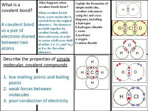
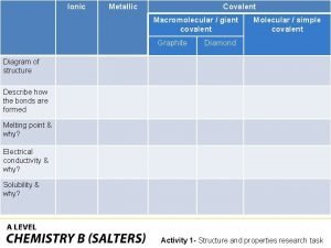
 Giant molecular structure vs simple molecular structure
 Giant molecular structure vs simple molecular structure
 Giant molecular structure vs simple molecular structure
 Molecular dynamics limitations
 Solutii finantare imm
 Pharmacy technician george brown
 Kiwisaver cec
 Dice one
 Cec roles and responsibilities
 Cec of kaolinite
 Lstm cec
 Changing our understanding
 Cec lstm
 Claim evidence and commentary
 Live and neutral wires
 Cec 220
 Cec tier 2
 Redecec
 Tes
Tes Cec last days of life toolkit


