
CEC 220 Digital Circuit Design More VHDL Fri


- Slides: 15
CEC 220 Digital Circuit Design More VHDL Fri, February 27 CEC 220 Digital Circuit Design Slide 1 of 15
Lecture Outline • More VHDL Fri, February 27 CEC 220 Digital Circuit Design Slide 2 of 15
More VHDL • To install Direct. VHDL on your personal computer: § CD in your textbook => VHDL-PEsetup-roth. exe § On the ERAU network => T: CEC 220Direct. VHDL-PEsetuproth. exe • Some examples => T: CEC 220Direct. VHDL-PEexamples Fri, February 27 CEC 220 Digital Circuit Design Slide 3 of 15
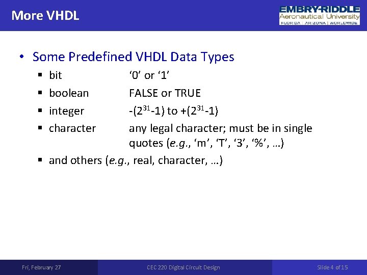
More VHDL • Some Predefined VHDL Data Types ‘ 0’ or ‘ 1’ FALSE or TRUE -(231 -1) to +(231 -1) any legal character; must be in single quotes (e. g. , ‘m’, ‘T’, ‘ 3’, ‘%’, …) § and others (e. g. , real, character, …) § § bit boolean integer character Fri, February 27 CEC 220 Digital Circuit Design Slide 4 of 15
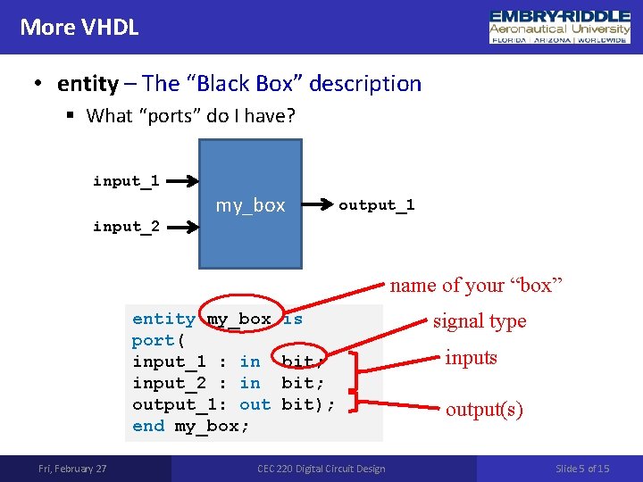
More VHDL • entity – The “Black Box” description § What “ports” do I have? input_1 my_box output_1 input_2 name of your “box” entity my_box port( input_1 : in input_2 : in output_1: out end my_box; Fri, February 27 is bit; bit); CEC 220 Digital Circuit Designal type inputs output(s) Slide 5 of 15
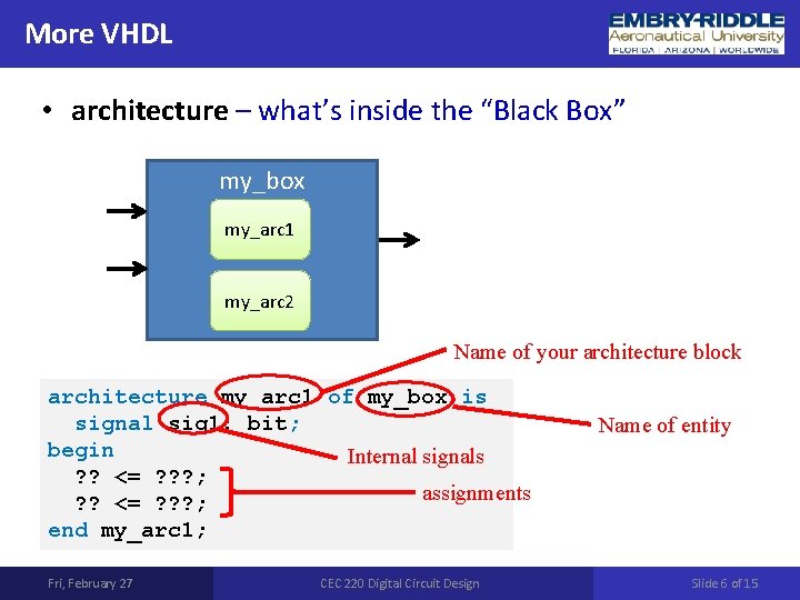
More VHDL • architecture – what’s inside the “Black Box” my_box my_arc 1 my_arc 2 Name of your architecture block architecture my_arc 1 of my_box is signal sig 1: bit; begin Internal signals ? ? <= ? ? ? ; assignments ? ? <= ? ? ? ; end my_arc 1; Fri, February 27 CEC 220 Digital Circuit Design Name of entity Slide 6 of 15
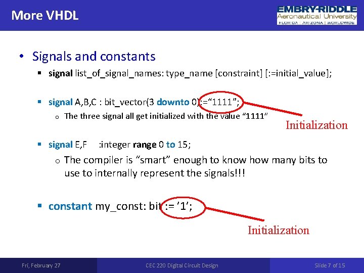
More VHDL • Signals and constants § signal list_of_signal_names: type_name [constraint] [: =initial_value]; § signal A, B, C : bit_vector(3 downto 0): =“ 1111”; o The three signal all get initialized with the value “ 1111” § signal E, F o Initialization : integer range 0 to 15; The compiler is “smart” enough to know how many bits to use to internally represent the signals!!! § constant my_const: bit : = ’ 1’; Initialization Fri, February 27 CEC 220 Digital Circuit Design Slide 7 of 15
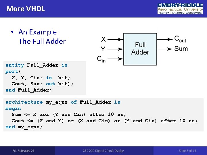
More VHDL • An Example: The Full Adder entity Full_Adder is port( X, Y, Cin: in bit; Cout, Sum: out bit); end Full_Adder; architecture my_eqns of Full_Adder is begin Sum <= X xor (Y xor Cin) after 10 ns; Cout <= (X and Y) or (X and Cin) or (Y and Cin) after 10 ns; end my_eqns; Fri, February 27 CEC 220 Digital Circuit Design Slide 8 of 15
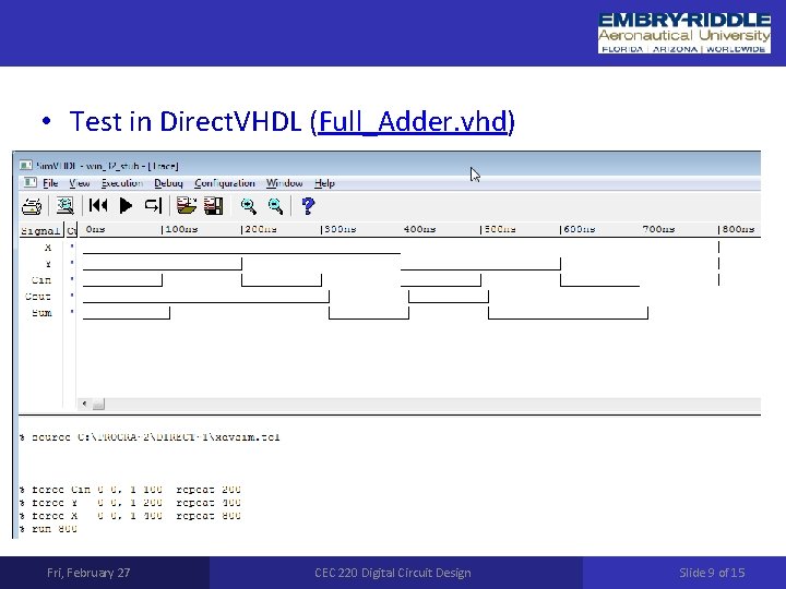
• Test in Direct. VHDL (Full_Adder. vhd) Fri, February 27 CEC 220 Digital Circuit Design Slide 9 of 15
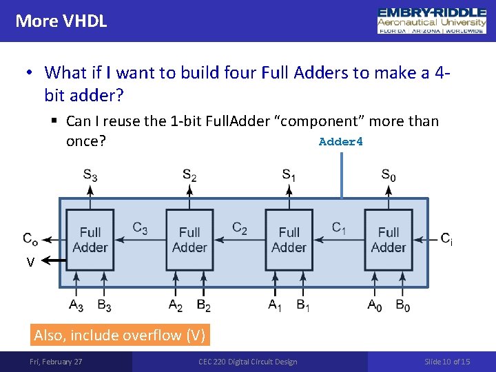
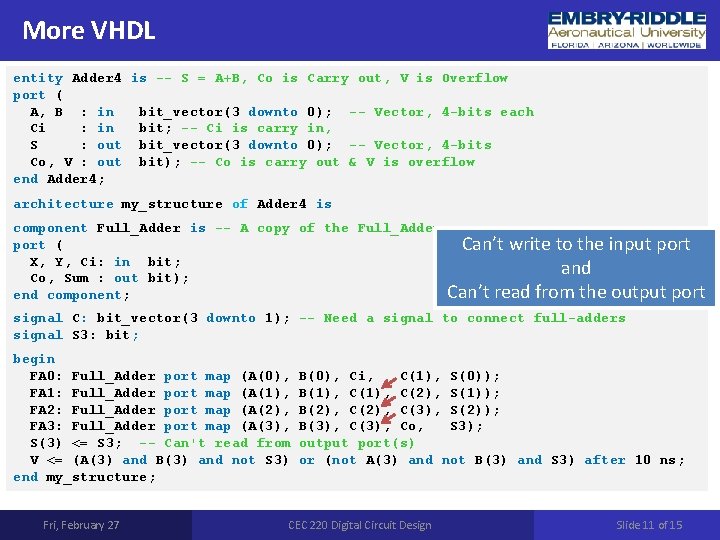
More VHDL • What if I want to build four Full Adders to make a 4 bit adder? § Can I reuse the 1 -bit Full. Adder “component” more than Adder 4 once? V Also, include overflow (V) Fri, February 27 CEC 220 Digital Circuit Design Slide 10 of 15
More VHDL entity Adder 4 is -- S = A+B, Co is Carry out, V is Overflow port ( A, B : in bit_vector(3 downto 0); -- Vector, 4 -bits each Ci : in bit; -- Ci is carry in, S : out bit_vector(3 downto 0); -- Vector, 4 -bits Co, V : out bit); -- Co is carry out & V is overflow end Adder 4; architecture my_structure of Adder 4 is component Full_Adder is -- A copy of the Full_Adder port ( X, Y, Ci: in bit; Co, Sum : out bit); end component; Can’t write to the input port and Can’t read from the output port signal C: bit_vector(3 downto 1); -- Need a signal to connect full-adders signal S 3: bit; begin FA 0: Full_Adder port map (A(0), FA 1: Full_Adder port map (A(1), FA 2: Full_Adder port map (A(2), FA 3: Full_Adder port map (A(3), S(3) <= S 3; -- Can't read from V <= (A(3) and B(3) and not S 3) end my_structure; Fri, February 27 B(0), Ci, C(1), S(0)); B(1), C(2), S(1)); B(2), C(3), S(2)); B(3), Co, S 3); output port(s) or (not A(3) and not B(3) and S 3) after 10 ns; CEC 220 Digital Circuit Design Slide 11 of 15
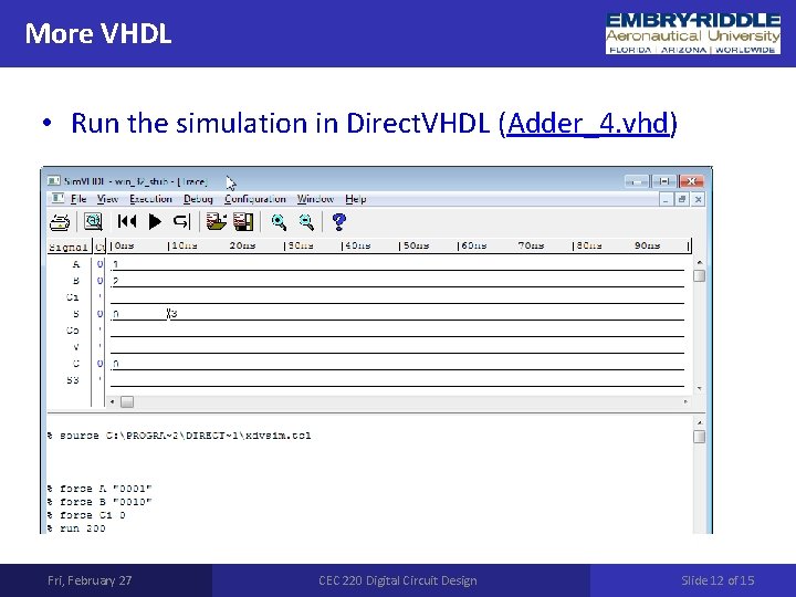
More VHDL • Run the simulation in Direct. VHDL (Adder_4. vhd) Fri, February 27 CEC 220 Digital Circuit Design Slide 12 of 15
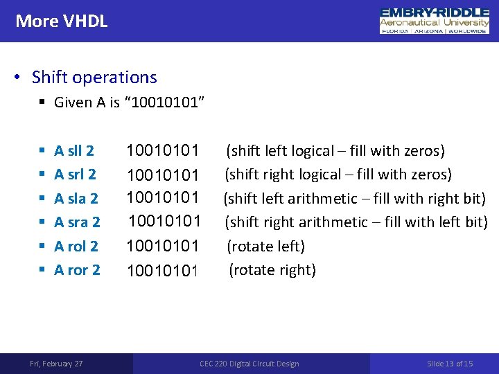
More VHDL • Shift operations § Given A is “ 10010101” § § § A sll 2 1001010100 (shift left logical – fill with zeros) A srl 2 0010010101 (shift right logical – fill with zeros) 1001010111 (shift left arithmetic – fill with right bit) A sla 2 A sra 2 1110010101 (shift right arithmetic – fill with left bit) 1001010110 (rotate left) A rol 2 A ror 2 0110010101 (rotate right) Fri, February 27 CEC 220 Digital Circuit Design Slide 13 of 15
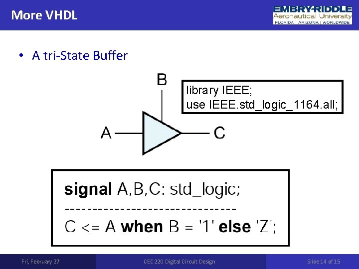
More VHDL • A tri-State Buffer library IEEE; use IEEE. std_logic_1164. all; Fri, February 27 CEC 220 Digital Circuit Design Slide 14 of 15
Next Lecture • Latches • Flip-Flops Fri, February 27 CEC 220 Digital Circuit Design Slide 15 of 15