Chapter Four Making Connections Weve been looking at

Chapter Four Making Connections. We’ve been looking at various methods of data transmission …how we send bits. but how do we communicate---how do we make sense of the bits that we send?

We must organize the bits that we send. We will be looking at communications standards. We examine: serial parallel synchronous asynchronous transmission.

POTS plain old telephone service

Telephone network

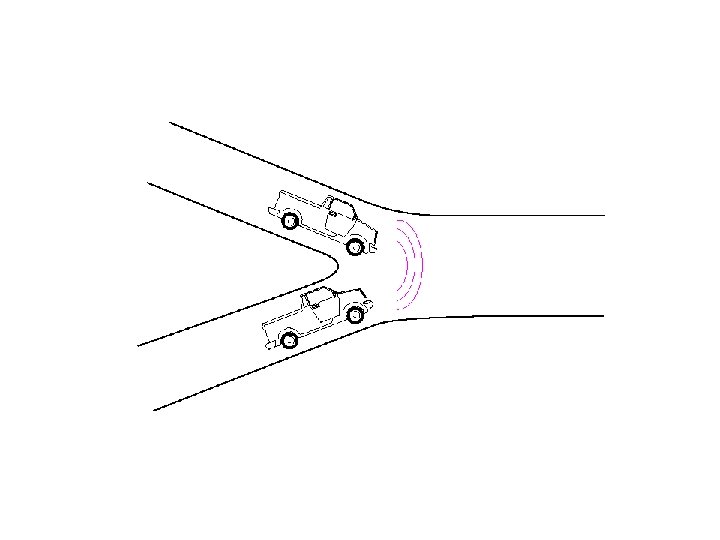
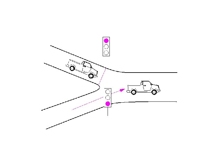
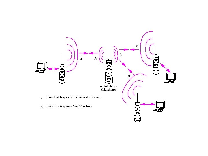
Cellular Phones

Transmission mode defines the way in which a bit group travels from one device to another. Serial/ parallel synchronous/asynchronous

Parallel and Serial Transmission

Asynchronous Transmission

Asynchronous Transmission example.

Synchronous Transmission

Simplex, Half-Duplex, or Full Duplex Transmission
 does")
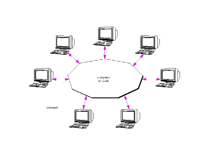
DTE Data Terminal Equipment DCE Data Circuit-terminating Equipment The DTE( ie, personal computer) does connect directly to the network, It communicates through a DCE (ie, modem). Interface Standards

EIA 232 connector
")
Sending and Receiving over an EIA 232 connection (RS 232)

Null Modem

RS 449 Interface

USB Universal Serial Bus. Overview A single USB device can be connected to the host or you may connect multiple devices using hubs. These hubs can in turn be connected in an hierarchical fashion. Up to 127 different devices can be connected to a single USB hub using an hierarchical arrangement.

Connecting USB Devices
 for data")
A USB cable connects devices. The cable contains 4 wires. 2 (twisted) for data and a power and ground. Uses a variation of NRZ encoding 0 defined by changing signal at beginning of bit period 1 defined by keeping signal constant.

Several versions. V 2. 0 bit rate 480 Mbps Signals are equal in magnitude and opposite in polarity (a balanced signal)

Two different types o plugs.

USB Data Transfer Operates in Master/slave mode. All devices are under control of host. Data is transferred in “frames”. . not the traditional frame that we define in the context of other protocols. In USB, a frame is a 1 millisecond slice of time. During that millisecond, information can be transmitted in “packets”. All connected devices are synchronized with respect to a frame. Host handles this. continued

Host sends a special packet to all connected devices to inform them that a new frame is beginning. What happens next is under control of the host and depends on the types of devices and what data is available for transfer.
 • control • bulk • isochronous")
USB defines four different transmission types (frame types) • control • bulk • isochronous • interrupt Each corresponds to a different type of exchange and is implemented by an exchange of packets.
")
Control Transfer: USB devices are hot pluggable…new devices can be plugged in (or unplugged) without powering off the system or loading new software. Host operating system must detect when a device is added or removed. Host queries to determine device type and bit rate Device responds to host, so host can identify the device.

Bulk Transfer: Some USB devices require the transfer of large amounts of data…ie, scanners. Data is stored in packets and transferred with error detecting mechanisms implemented on the receiving end. Service is guaranteed reliable but not necessarily in a timely fashion since many devices may be competing.

Interrupt Transfers: Some peripherals operate using interrupts ie a disk controller. Generates an interrupt. USB does not operate this way. When a device has data to transfer, it simply holds the data and waits for the host to ask. This technique is called polling.
 require real time data transfer. Data must")
Isochronous Transfer: Some USB devices (microphones, speakers) require real time data transfer. Data must be sent at guaranteed intervals. Host can reserve a part of each frame (time slice) for that device and guarantee a steady flow of information.

USB Packets In general, there can be several exchanges of packets during a single frame. Three packet types: • token • data • handshake

All packet types contain a SYN field and PID, packet identification field. The SYN field allows the receiving device to synchronize its internal clock with the rate at which the bits are arriving. PID field identifies the packet type. A device can receive a packet at any time and must have some way to identify the type of packet it is getting.

TOKEN PACKET: host uses token packet to send info or requests to a USB device. Several kinds of token packets: • start of frame (SOF) Recall every devices is synchronized to the start of frame. this frame is sent to all devices.

IN packets and OUT packets: Each represents a request from the host to begin data transfer. The only difference between the two is the direction of the transfer. Out goes from host to device.

The OUT packet process. After sending an SOF packet, the host sends an OUT packet which contains the address of the target USB device. This packet also contains a CRC field for error detection. Next the host sends the data packet. If there are no errors the device sends an ACK packet. If there are errors the device sends a NAK packet and the process is repeated.

There is no address field in the data packet. The endpoint field in the OUT packet is used to direct info to a specific point on the device, particular button for example.

USB Packets

FIREWIRE: Began development in late 1980’s. A standard IEEE 1394 was adopted in 1995. Firewire has much in common with USB: • hot swappable • plug and play • serial connections • standard way to connect a wide variety of devices • relatively inexpensive to implement • Latest info: up to 63 devices • firewire is faster *at present.

Connecting firewire devices Daisy chain, max length about 4. 5 meters between pairs

Firewire uses eight wires instead of four: • two power supplies • two twisted pair; TPA and TPB • Uses “data strobe encoding” Data are encoded using a form of NRZ, 1 = high; 0=low Receiver gets data over TPA TPB is used by sender to send a strobe signal for synchronization. If data changes, strobe remains constant, if data remains constant, strobe changes. Using EXOR logic the receiver can reproduce the sender’s clock signal.

Data Strobe Encoding

Firewire is a peer-to-peer protocol Communications do not depend on a single host, such as a PC. May be daisy chained together to form a bus group The bridges isolate the groups from one another. There may be up to 63 devices in one group (uses 6 bit ID) and up to 1023 different groups (10 bit ID.

Daisy Chained Firewire Devices

Firewire Communications: Two Modes: Asynchronous Isosynchronous

Asynchronous: • • send a packet wait for response if ACK consider packet received if NACK resend Isochronous behaves as previously described.

Since communication is peer-to-peer, devices can initiate their communications at any time. How do we handle conflicts ARBITRATION; The system uses a tree structure, the device at the root is the arbiter and decides who gets access.

This is only part of the process. Two other methods are also used. Fairness arbitration: essentially a round robin process Urgent Arbitration: certain devices can be configured as urgent. This is still not isochronous. that works similarly to USB

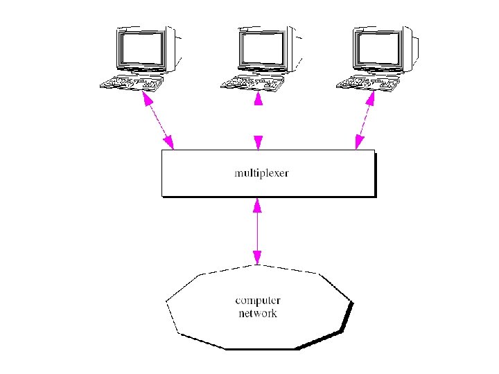
Multiplexing: Allows multiple slower speed devices to share and more fully utilize a high speed network

FREQUENCY DIVISION MULTIPLEXING: This is a technique to allow multiple messages to share a single transmission line. Signals from multiple sources each with an assigned bandwidth, these, in turn, are combined to form a more complex signal across a much larger bandwidth.

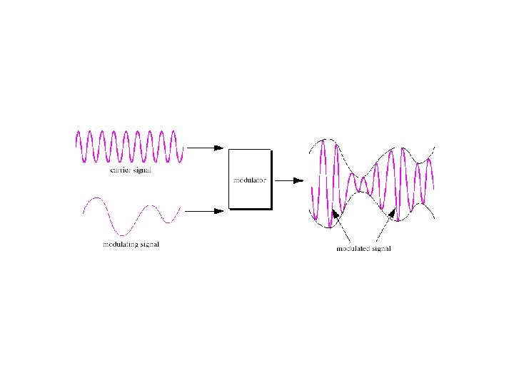
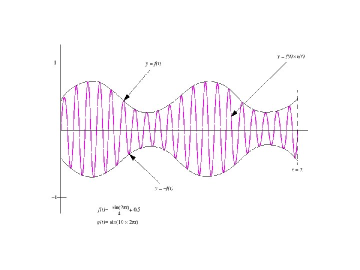
FDM process. Available bandwidth is divided into separate ranges or channels. A carrier signal is defined for each channel, that carrier frequency is modulated by the data signal for that channel.

Frequency Division Multiplexing

Time Division Multiplexing or Synchronous Time Division Multiplexing

Data Rate of output equals sum of all of the inputs for synchronous time division multiplexing Statistical TDM recognizes that all connected devices do not continuously communicate. Combine line output capacity can be less than sum of possible inputs from all sources. Must have buffering capability.

Statistical Time Division Multiplexing

For Fiber Optics: use Wavelength Division Multiplexing WDM Light consists of multiple wavelengths. The data from each of these multiple sources is encoded onto light of a particular wavelength which are, in turn, combined into a single light source. Light can be separated into its various wavelengths using prisms for example. The process is, of course, more complex than that.

Digital Carrier Standards: One approach uses T 1 transmission and DS 1 signaling. These refer to the circuit and signal respectively.

T 1: defined for voice communication 24 channels each one contains a single telephone call Uses PCM to digitize the voice data; 8 bit samples taken at 8000 samples per second. Each sample occupies one slot in a DS 1 frame ( 193 bits/ frame … 24 channels at 8 bits each with 1 bit left for framing. ) These frames are generated at the rate of 8000 per second for a total bit rate of 1. 544 Mbps.

These standards are hierarchical: T 2 is obtained by multiplexing 4 T 1’s (DS 1’s) T 3 is 28 DS 1 frames or 672 channels in each frame.
 Many levels of SONET lowest level is")
SONET: Synchronous Optical Network (Bell Communications Research) Many levels of SONET lowest level is 51. 84 Mbps
 second")
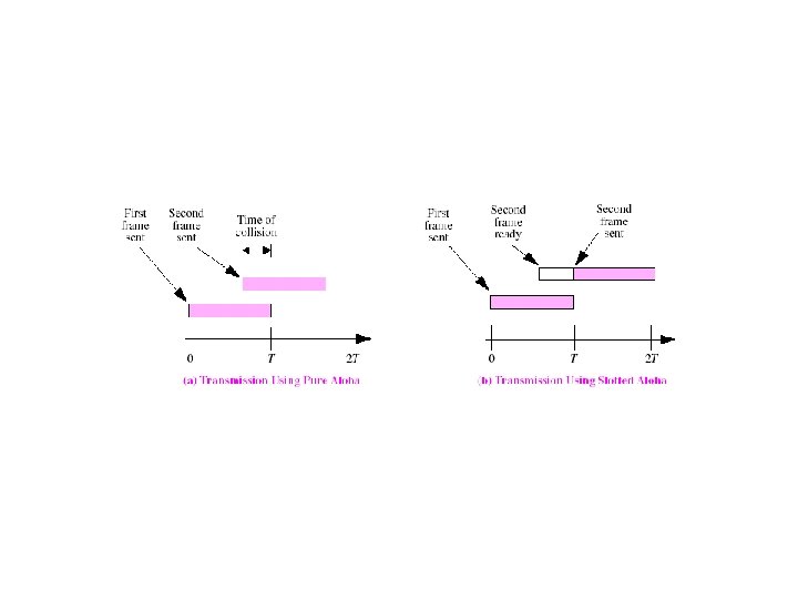
Binary Exponential Backoff Algorithm first time collision…wait 0 or 1 time slot (random) second time. . wait 0, 1, 2, 3 time slots (random) third collision. . wait 0 -7 slots (random) in general, increase value of n upon each collision and wait a randomly chosen 0 – 2 n-1 slots n = 10 0 -1023 slots after 16 collisions, give up.

END OF CHAPTER 4
- Slides: 75