Chapter 30 Electronic Fuel Injection Electronic Fuel Injection


 • During closed loop the PCM relies on input from sensors")


 • The amount of fuel injected depends on fuel pressure and")

 • The PCM increases or decreases idle air bypass depending")

 – TP sensors are used to clarify load and operating conditions. –")


 • The system allows for short term (STFT) and long term")
 • • • Used to move from carburetors to fuel")
 • At least one injector per cylinder. • Delivers fuel")
 • Sequential Injection (SFI) – Each injector is fired individually")


 Features • Gasoline Direction Injection (GDI) – Allows for very")


- Slides: 46
Chapter 30 Electronic Fuel Injection
Electronic Fuel Injection • The ideal fuel ratio is called stoichiometric. • This means all of the fuel and oxygen are completely consumed during combustion. • The ideal environment rarely exists. • The FI system adjusts to changes for starting, maximum power, and maximum economy.
Basic EFI • The PCM must know the amount of air entering the engine. • In MAP sensor systems, air flow is calculated based on intake manifold pressure and RPM – called a speed density system. • MAF sensor systems directly measure incoming air flow.
Basic EFI (cont’d) • During closed loop the PCM relies on input from sensors to adjust the air/fuel ratio. • The PCM uses inputs and look-up tables in memory to determine the ideal mixture. • During starting and wide-open throttle the system is in open loop.
Open and Closed Loop
Fuel Injectors • Electromechanical devices that meters and atomize fuel
Fuel Injectors (cont’d) • The amount of fuel injected depends on fuel pressure and injector pulse width time. • Typical pulse width is 1 – 10 ms at full load. • Primary factors are load and engine temperature. • Injector design and fuel additives help reduce injector tip deposits and clogging.
Idle Speed Control • On non-ETC engines, idle speed controlled with bypass air
Idle Speed Control (cont’d) • The PCM increases or decreases idle air bypass depending on engine speed, temperature, and load. • During cold starts, the PCM keeps idle speed high to raise catalytic converter temperature.
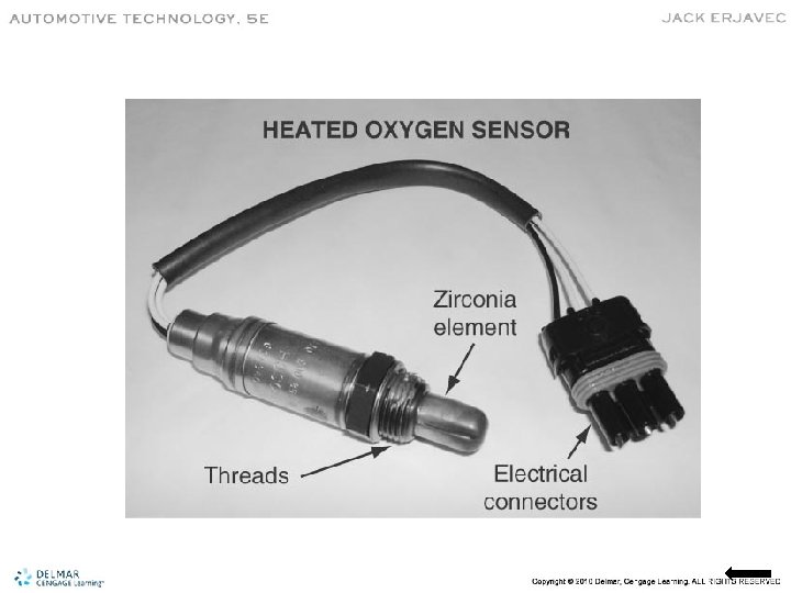
Inputs • Injector control based on sensor input – MAF sensors measure incoming air volume and density. – MAP sensors detect changes in intake manifold pressure. – O 2 sensors monitor exhaust oxygen content. – IAT sensors measure incoming air temperature. – ECT sensors monitor engine coolant temperature.
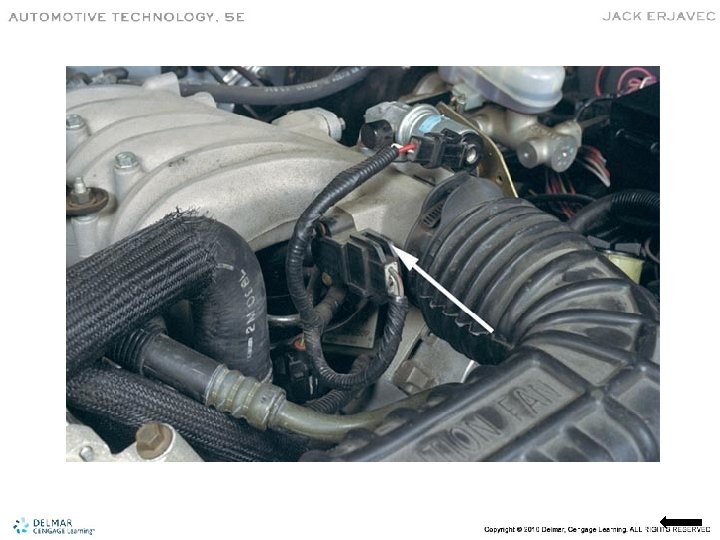
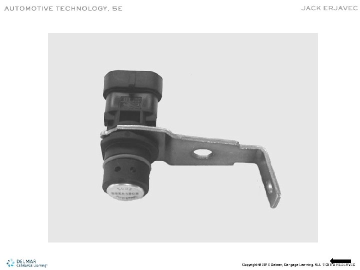
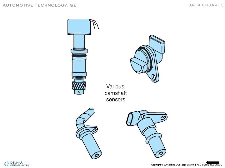
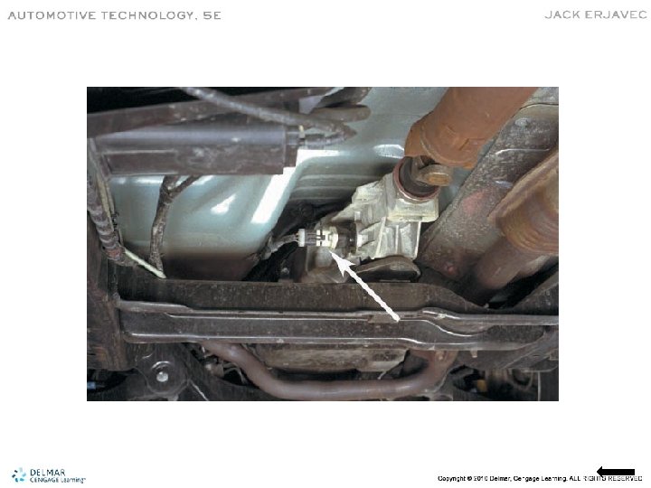
Inputs (cont’d) – TP sensors are used to clarify load and operating conditions. – CKP sensors monitor engine speed. – CMP sensors used to synchronize injector firing. – VSS is used to further define operating conditions.
Starting Mode • Fuel pump activated for two seconds and after CKP reference received. • PCM uses CKP to determine firing order. • Injector pulse width determined by: – ECT, MAF, IAT, and TP
Run Mode • Once a predetermined RPM is reached, system goes into open loop. • Injector pulse width set by: – MAF, IAT, ECT, TP • Closed loop begins based on input from the ECT and O 2 sensors.
Acceleration Mode • Based on signals from TP and MAF. • To compensate, the PCM increases injector pulse width. • Once the PCM determines the vehicle is no longer accelerating, the system returns to run mode.
Deceleration Mode • Inputs from MAF and TP used to determine deceleration. • PCM reduces injector pulse width. • Some systems complete shut the injector off during rapid deceleration.
Fuel Trim • PCM constantly monitors HO 2 S or air-fuel ratio sensors in closed loop. • Alters injector pulse width to provide the best driveability, economy, and emission control. • Expressed as a percentage. • Base pulse width is 0 percent.
Fuel Trim (cont’d) • The system allows for short term (STFT) and long term (LTFT) changes. • LTFT are changes to set a new pulse width.
Throttle Body Injection (TBI) • • • Used to move from carburetors to fuel injection. Use one or two injectors over the throttle plate. Not as efficient as port fuel injection. No longer in use. Fuel pressure typically 10 – 15 psi.
Port Fuel Injection (PFI) • At least one injector per cylinder. • Delivers fuel just outside combustion chamber. • Allows for good atomization. • Several different types used over years: – Multiport injection (MPI) – Sequential fuel injection (SFI)
Sequential Fuel Injection (SFI) • Sequential Injection (SFI) – Each injector is fired individually just before the intake valve for that cylinder opens • Typically use MAF sensors • Injectors fire according to CKP
Throttle Body • Controls air entering the engine and vacuum in the intake. • May contain a MAP sensor, IAC assembly, throttle plate(s), and TP sensor. • Many throttle body bores and plates coated with a special coating to prevent carbon buildup.
Fuel Delivery • • • Injectors controlled separately by PCM. Fuel supplied to the injectors by the fuel rail. The rail may contain a pressure test port. V engines usually have left and right rails. Some engines use variable intake runners for high and low speed operation.
Typical Fuel Rail
Pulsation Damper • Reduces pulsations caused by rapid opening and closing of injectors
Injector Control • Injector opening timed to occur before the intake valve opens. • SFI engines require CKP and CMP input to fire each injector.
Pressure Regulators • MPI injector tips are located in the intake manifold where constant changes in vacuum affect fuel delivery. • The fuel pressure regulator adjusts fuel pressure to maintain a constant pressure drop for each injector.
Returnless Systems • Most newer systems have the pressure regulator as part of the fuel sender/pump. • Only the fuel needed by the engine is filtered and sent to the injectors.
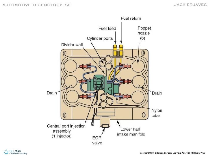
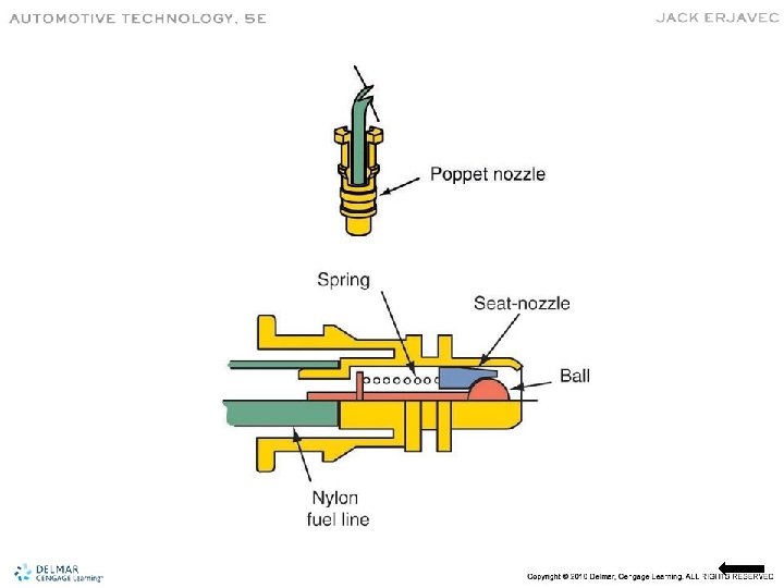
Central Multi-Port Fuel Injection • • • Uses one central injector. Fuel is delivered to individual poppet nozzles. Fuel pressure is higher than most PFI systems. Poppet nozzles snap into lower intake. Each nozzle contains a check ball and spring. The nozzle opens when pressure exceeds 37 – 43 psi.
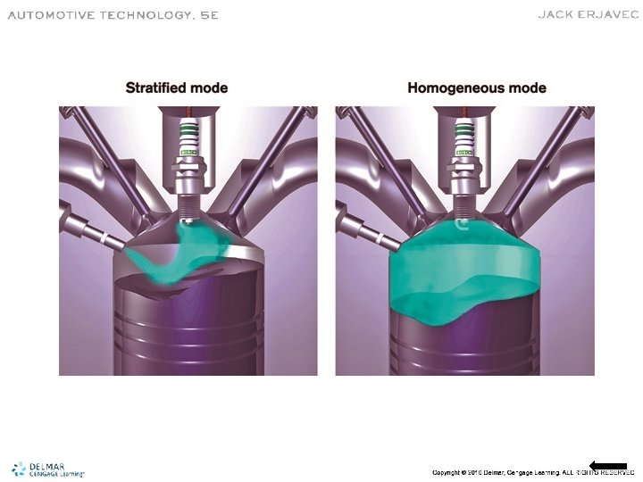
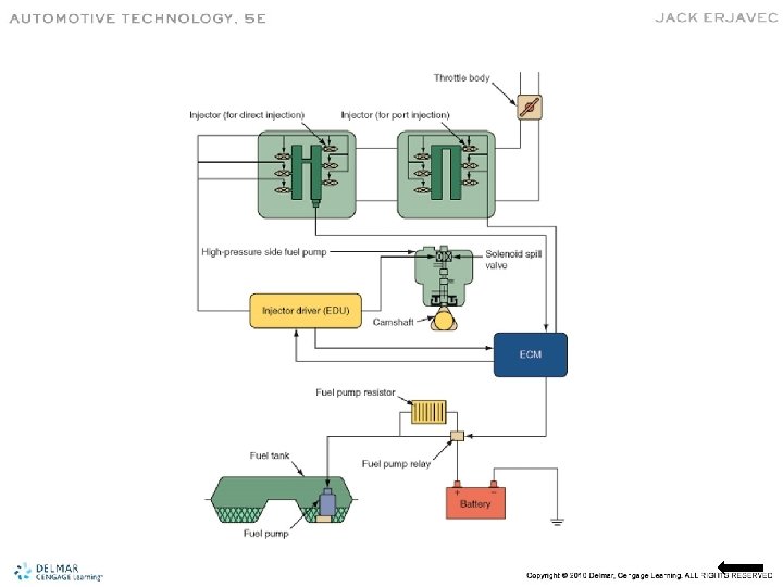
Gasoline Direct-Injection Systems • Used for many years on diesel engines. • Highly pressurized fuel is sprayed directly into the cylinders.
Gasoline Direct Injection (GDI) Features • Gasoline Direction Injection (GDI) – Allows for very lean air/fuel mixtures – Increases volumetric efficiency – Uses very high fuel pressures (typically between 400 and 1500 psi) – System operates similarly to diesel injection systems
Operational Modes • Lean Burn – Can run as high as 60: 1 • Stoichiometric – During medium load • Full Power – During heavy loads and hard acceleration
Advantages of GDI • • Increased fuel economy High power output Increases engine volumetric efficiency Lowers engine thermal loss Decreases emissions Allows higher compression Reduces most turbo lag when turbocharged
Light-Medium Duty Diesel Fuel Injection • GDI systems are very similar to modern light and medium duty diesel systems. • To meet OBD standards, diesel control systems use same inputs as gas engines. • Fuel rail pressure can range from 2000 to 25, 000 psi.
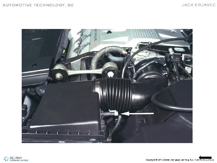
Mass Airflow Sensor
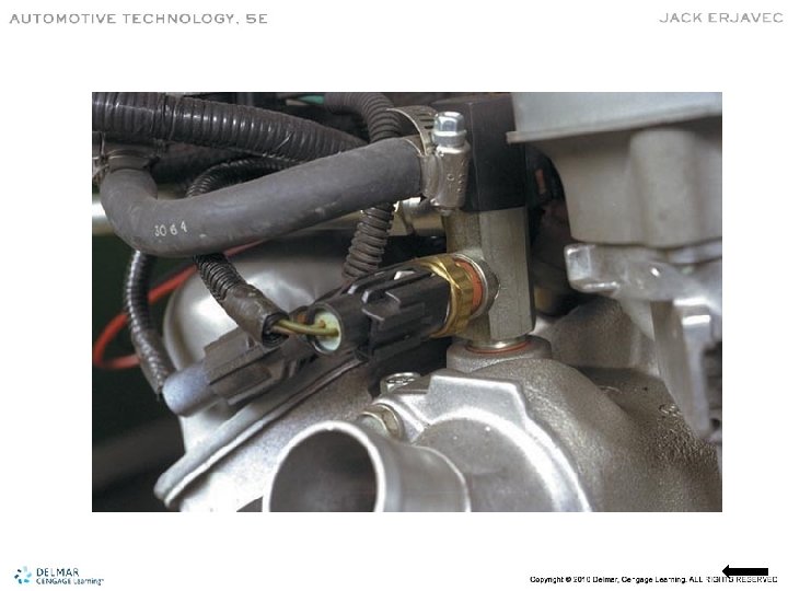
MAP Sensor