ELECTRONIC FUEL INJECTION EFI Electronic fuel injection In
")


 x (Factor A) x (Factor B) In order")


- Slides: 28
ELECTRONIC FUEL INJECTION (EFI)
Electronic fuel injection • In trying to keep up with emissions and fuel efficiency laws, the fuel system used in modern cars has changed a lot over the years. The 1990 Subaru Justy was the last car sold in the United States to have a carburetor; the following model year, the Justy had fuel injection. But fuel injection has been around since the 1950 s, and electronic fuel injection was used widely on European cars starting around 1980. Now, all cars sold in the United States have fuel injection systems. The Fall of the Carburetor • For most of the existence of the internal combustion engine, the carburetor has been the device that supplied fuel to the engine. On many other machines, such as lawnmowers and chainsaws, it still is. But as the automobile evolved, the carburetor got more and more complicated trying to handle all of the operating requirements. For instance, to handle some of these tasks, carburetors had five different circuits:
CIRCUITS • Main circuit - Provides just enough fuel for fuel-efficient cruising • Idle circuit - Provides just enough fuel to keep the engine idling • Accelerator pump - Provides an extra burst of fuel when the accelerator pedal is first depressed, reducing hesitation before the engine speeds up • Power enrichment circuit - Provides extra fuel when the car is going up a hill or towing a trailer • Choke - Provides extra fuel when the engine is cold so that it will start
In order to meet stricter emissions requirements, catalytic converters were introduced. Very careful control of the air-to-fuel ratio was required for the catalytic converter to be effective. Oxygen sensors monitor the amount of oxygen in the exhaust, and the engine control unit (ECU) uses this information to adjust the air-to-fuel ratio in real-time. This is called closed loop control -- it was not feasible to achieve this control with carburetors. There was a brief period of electrically controlled carburetors before fuel injection systems took over, but these electrical carbs were even more complicated than the purely mechanical ones. At first, carburetors were replaced with throttle body fuel injection systems (also known as single point or central fuel injection systems) that incorporated electrically controlled fuel-injector valves into the throttle body. These were almost a bolt-in replacement for the carburetor, so the automakers didn't have to make any drastic changes to their engine designs. Gradually, as new engines were designed, throttle body fuel injection was replaced by multi-port fuel injection (also known as port, multi-point or sequential fuel injection). These systems have a fuel injector for each cylinder, usually located so that they spray right at the intake valve. These systems provide more accurate fuel metering and quicker response.
When You Step on the Gas The gas pedal in your car is connected to the throttle valve -- this is the valve that regulates how much air enters the engine. So the gas pedal is really the air pedal. When you step on the gas pedal, the throttle valve opens up more, letting in more air. The engine control unit (ECU, the computer that controls all of the electronic components on your engine) "sees" the throttle valve open and increases the fuel rate in anticipation of more air entering the engine. It is important to increase the fuel rate as soon as the throttle valve opens; otherwise, when the gas pedal is first pressed, there may be a hesitation as some air reaches the cylinders without enough fuel in it.
The Injector
Injector • A fuel injector is nothing but an electronically controlled valve. It is supplied with pressurized fuel by the fuel pump in your car, and it is capable of opening and closing many times per second. When the injector is energized, an electromagnet moves a plunger that opens the valve, allowing the pressurized fuel to squirt out through a tiny nozzle. The nozzle is designed to atomize the fuel -- to make as fine a mist as possible so that it can burn easily.
PULSE WIDTH • The amount of fuel supplied to the engine is determined by the amount of time the fuel injector stays open. This is called the pulse width, and it is controlled by the ECU.
• The injectors are mounted in the intake manifold so that they spray fuel directly at the intake valves. A pipe called the fuel rail supplies pressurized fuel to all of the injectors.
• In order to provide the right amount of fuel, the engine control unit is equipped with a whole lot of sensors
Engine Sensors • In order to provide the correct amount of fuel for every operating condition, the engine control unit (ECU) has to monitor a huge number of input sensors • Mass airflow sensor • Oxygen sensor(s) • Throttle position sensor • Coolant temperature sensor • Manifold absolute pressure sensor • Voltage sensor • Engine speed sensor
Engine Controls and Performance Chips The algorithms that control the engine are quite complicated. The software has to allow the car to satisfy emissions requirements for 100, 000 miles, meet EPA fuel economy requirements and protect engines against abuse. And there are dozens of other requirements to meet as well. The engine control unit uses a formula and a large number of lookup tables to determine the pulse width for given operating conditions. The equation will be a series of many factors multiplied by each other. Many of these factors will come from lookup tables. We'll go through a simplified calculation of the fuel injector pulse width. In this example, our equation will only have three factors, whereas a real control system might have a hundred or more.
Pulse width = (Base pulse width) x (Factor A) x (Factor B) In order to calculate the pulse width, the ECU first looks up the base pulse width in a lookup table. Base pulse width is a function of engine speed (RPM) and load (which can be calculated from manifold absolute pressure). Let's say the engine speed is 2, 000 RPM and load is 4. We find the number at the intersection of 2, 000 and 4, which is 8 milliseconds. RPM Load 1 2 3 4 5 1, 000 1 2 3 4 5 2, 000 2 4 6 8 10 3, 000 3 6 9 12 15 4, 000 4 8 12 16 20
In the next examples, A and B are parameters that come from sensors. Let's say that A is coolant temperature and B is oxygen level. If coolant temperature equals 100 and oxygen level equals 3, the lookup tables tell us that Factor A = 0. 8 and Factor B = 1. 0. function of load and RPM, and that pulse width = (base pulse width) x (factor A) x (factor B), the overall pulse width in our example So, since we know that base pulse width is a equals: 8 x 0. 8 x 1. 0 = 6. 4 milliseconds A Factor A B Factor B 0 1. 2 0 1. 0 25 1. 1 1 1. 0 50 1. 0 2 1. 0 75 0. 9 3 1. 0 100 0. 8 4 0. 75
From this example, you can see how the control system makes adjustments. With parameter B as the level of oxygen in the exhaust, the lookup table for B is the point at which there is (according to engine designers) too much oxygen in the exhaust; and accordingly, the ECU cuts back on the fuel. Real control systems may have more than 100 parameters, each with its own lookup table. Some of the parameters even change over time in order to compensate for changes in the performance of engine components like the catalytic converter. And depending on the engine speed, the ECU may have to do these calculations over a hundred times per second.
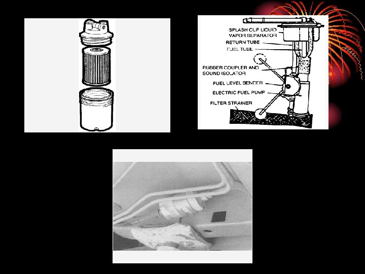
The fuel delivery system consists of all the components which supply the engine with fuel. This includes the tank itself, all the lines, one or more fuel filters, a fuel pump (mechanical or electric), and the fuel metering components (carburetor or fuel injection system). Fuel tanks are normally located at the rear of the vehicle, although on rear or mid engine vehicles they are usually located at the front. The tank contains a fuel gauge sending unit, a filler tube and on most fuel injected vehicles, a fuel pump. In most tanks, there is also a fine mesh screen "sock" attached to the pickup tube. This is used to filter out large particles which could easily clog the fuel lines, fuel pump and fuel filter.
Since the advent of emission controls, tanks are equipped with a control system to prevent fuel vapor from being discharged into the atmosphere. A vent line in the tank is connected to an activated carbon or charcoal filled canister in the engine compartment. Vapors from the tank are stored in this canister, until they can be purged later for combustion in the engine. On many carbureted engines, the float bowl is also vented to this canister. Fuel pumps Mechanical pumps are usually found on carbureted engines or on engines that utilize a mechanical fuel injection system.
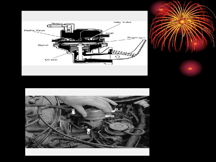
Mechanical fuel pumps on carbureted engines are usually mounted on the side of the engine block or cylinder head and operated by an eccentric on the engine's camshaft. The rocker arm of the pump rests against the camshaft eccentric, and as the camshaft rotates, it actuates the rocker arm. Some engines use a pushrod between the rocker arm and camshaft eccentric. Inside the fuel pump, the rocker arm is connected to a flexible diaphragm. A spring, mounted underneath, maintains pressure on the diaphragm. As the rocker arm is actuated, it pulls the diaphragm down and then releases it. Once the diaphragm is released, the spring pushes it back up. This continual diaphragm motion causes a partial vacuum and pressure in the space above the diaphragm. The vacuum draws the fuel from the tank and the pressure pushes it toward the carburetor or injection pump. A check valve is used in the pump to prevent fuel from being pumped back into the tank.
Certain mechanical fuel injection systems also utilize a mechanical fuel pump, typically some diesel engines and early gasoline fuel injection systems. Many of them use a fuel pump essentially identical to the carbureted fuel system's. Some, however, use a vane type fuel pump mounted directly to the injection pump/fuel distributor assembly. The injection pump/fuel distributor assembly is driven by the timing belt, chain or gears which in turn drives the fuel pump. The vanes draw the fuel in through the inlet port then squeeze the fuel into a tight passage. The fuel then exits pressurized through the outlet port. Electric pumps There are two general types of electric fuel pumps: the impeller type and the bellows type. Electric pumps can be found on all types of fuel systems.
The impeller type pump uses a vane or impeller that is driven by an electric motor. These pumps are often mounted in the fuel tank, though they are sometimes found below or beside the tank. The vanes or impeller draw the fuel in through the inlet port then squeeze the fuel into a tight passage. This pressurizes the fuel. The pressurized fuel then exits through the outlet port.
The bellows type pump is rare. This pump is ordinarily mounted in the engine compartment and contains a flexible metal bellows operated by an electromagnet. As the electromagnet is energized, it pulls the metal bellows up. This draws the fuel from the tank into the pump. When the electromagnet is de-energized, the bellows returns to its original position. A check valve closes to prevent the fuel from returning to the tank. The only place for the fuel to go now is through the outlet port. Fuel filters In addition to the mesh screen attached to the pickup tube, all fuel systems have at least one other filter located somewhere between the fuel tank and the fuel metering components. On some models, the filter is part of the fuel pump itself, on others, it is located in the fuel line, and still others locate the filter at the carburetor or throttle body inlet.
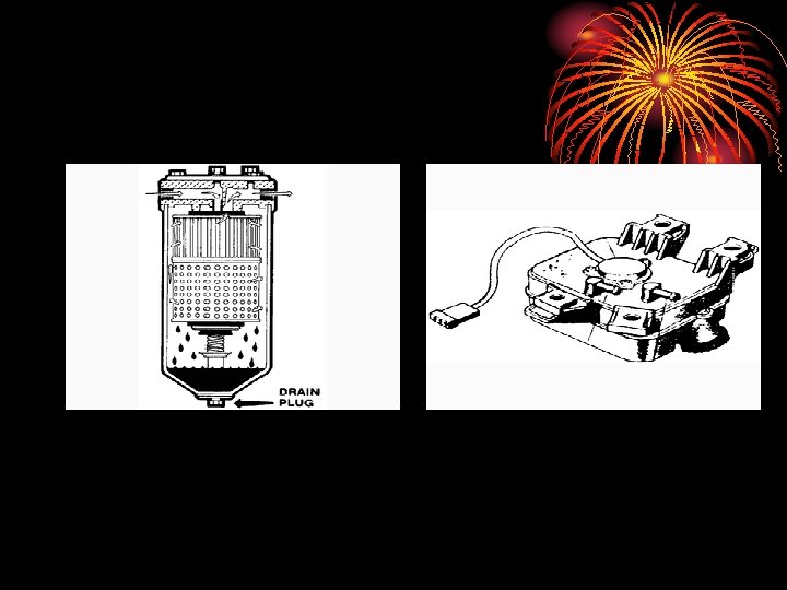
Inline and spin-on filters are located between the fuel pump and fuel metering components. They are connected to fuel lines either by clamps, banjo bolts, flare fittings or quick-disconnect fittings. Most are "throw-away" units with a paper element encased in a housing. Some have a clear plastic housing that allows you to view the amount of dirt trapped in the filter. Some filters consist of a replaceable pleated paper cartridge installed in a permanent filter housing. Their use is limited mostly to diesel and heavy-duty gasoline engines.
Carburetor/Throttle Body Inlet Filters Fuel filters can also be located in the carburetor or throttle body inlet. For carburetors, they consist of a small paper or bronze filter that is installed in the inlet housing. They are extremely simple in design and are about as efficient as an inline type. The bronze filter is the least common and must be installed with the small cone section facing out. One type is held in place by a threaded metal cap that attaches to the fuel line and screws into the carburetor fuel inlet. On another type, the fuel filter threads directly into the carburetor. On throttle body units, these filters are used as a supplement to the primary inline filter. They usually consist of a conical screen, similar in appearance to an air conditioning orifice tube. They can be accessed after removing the fuel line from the throttle body unit.
Fuel/water separator This is usually found on diesel cars and trucks. It can either be part of the fuel filter housing or it can be a separate remote unit all together. Most operate as a twostage filter. The lower stage removes dirt particles down to about 1 micron in size and allows the water to form large droplets. In the second stage, fuel freely passes through the filter, but water will not. Water collects in the bottom of the filter housing, and a drain plug on the bottom of the housing is usually provided. The separate units are usually mounted next to the fuel tank. They collect water as it settles out of the fuel tank. Some may light a warning lamp on the dash when it requires draining.