
EPA Compliant Fuel Systems IBEX Sep 28 2010
EPA Compliant Fuel Systems IBEX Sep 28, 2010 Sean Whelan P. E. 1
Agenda 1. Which diurnal system should I choose 2. What is Automatic Shut off/no spit back & how do I meet it 3. Automatic shut off in cars & trucks 4. Venting and Thermal Expansion 5. Engine Performance & Fuel Line Pressure Drop 6. Safety Considerations 7. Technical Considerations 2
Which Architecture do I choose? Diurnal Systems (all) • Can I fit a new tank with diurnal components mounted? • How do I maintain accessibility of all attachments? Carbon Canister System • Can I fit a carbon canister in my boat? • How do I prevent liquid gas and water from entering the canister? Pressure Release System • Can I prevent fuel line from pressurizing or do I need rigid fuel lines? • Can my new tank assembly withstand the pressure cycles over time? • Is there room for my tank to swell under pressure without contacting deck or hull? • Do I have sufficient pressure drop budget in my engine(s)?
What Is Automatic Shut Off
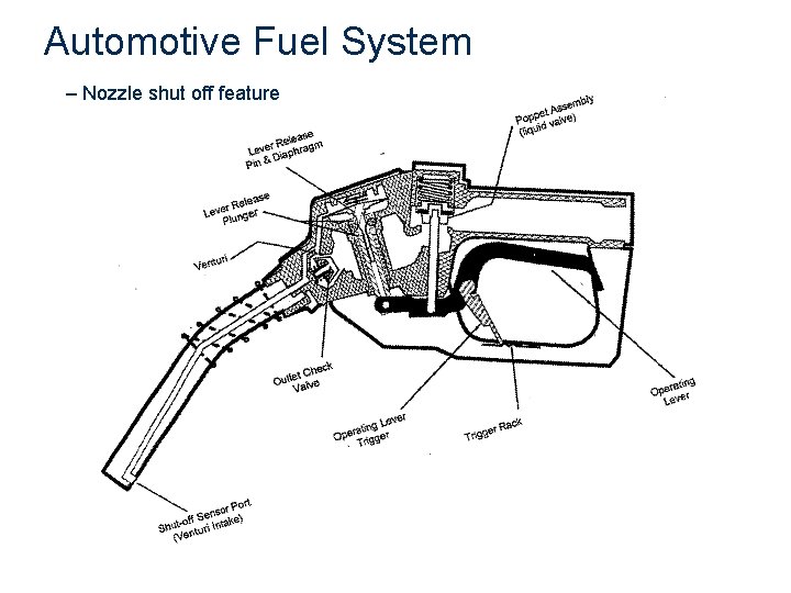
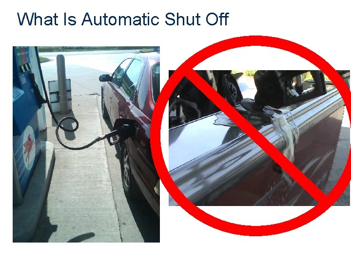
Automotive Fuel System – Nozzle shut off feature
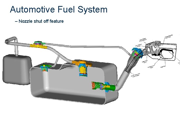
Automotive Fuel System – Nozzle shut off feature
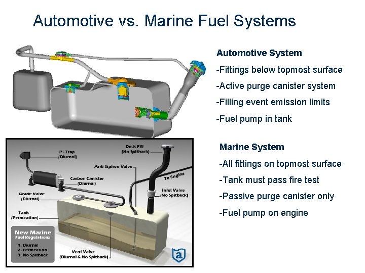
Automotive vs. Marine Fuel Systems Automotive System -Fittings below topmost surface -Active purge canister system -Filling event emission limits -Fuel pump in tank Marine System -All fittings on topmost surface -Tank must pass fire test -Passive purge canister only -Fuel pump on engine 7
Refueling Considerations • How will the system handle high and low RVP fuels? • How will the system handle high and low temperature refueling events? • Will my boat be compatible with marina fuel fills of larger sizes? • Will my customer be safe after filling boat with a jerry can?
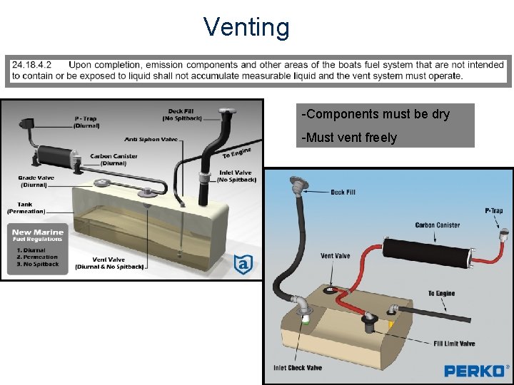
Venting -Components must be dry -Must vent freely
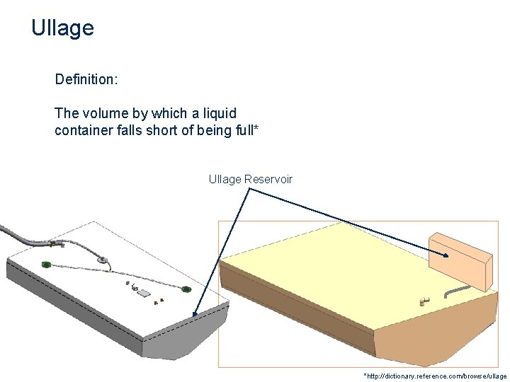
Ullage Definition: The volume by which a liquid container falls short of being full* Ullage Reservoir *http: //dictionary. reference. com/browse/ullage
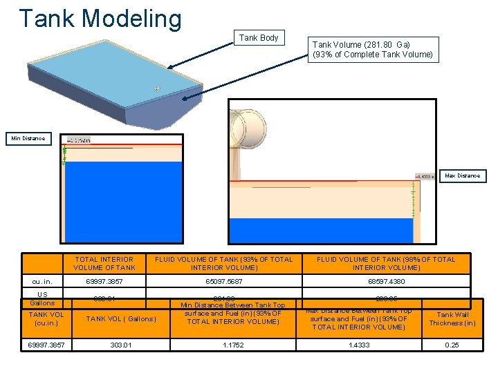
Tank Modeling Tank Body Tank Volume (281. 80 Ga) (93% of Complete Tank Volume) Min Distance Max Distance TOTAL INTERIOR VOLUME OF TANK FLUID VOLUME OF TANK (93% OF TOTAL INTERIOR VOLUME) FLUID VOLUME OF TANK (98% OF TOTAL INTERIOR VOLUME) cu. in. 69997. 3857 65097. 5687 68597. 4380 US Gallons 303. 01 TANK VOL (cu. in. ) TANK VOL ( Gallons) 281. 80 Min Distance Between Tank Top surface and Fuel (in) (93% OF TOTAL INTERIOR VOLUME) 69997. 3857 303. 01 1. 1752 296. 95 Max Distance Between Tank Top surface and Fuel (in) (93% OF TOTAL INTERIOR VOLUME) Tank Wall Thickness (in) 1. 4333 0. 25
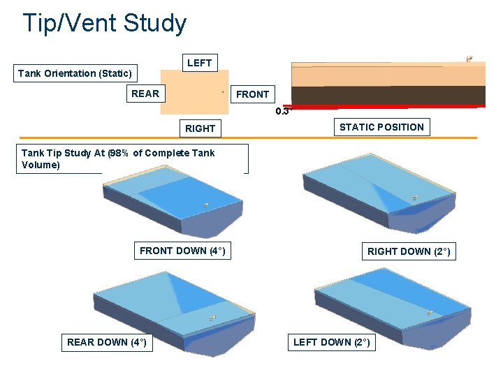
Tip/Vent Study LEFT Tank Orientation (Static) REAR FRONT 0. 3° RIGHT STATIC POSITION Tank Tip Study At (98% of Complete Tank Volume) FRONT DOWN (4°) REAR DOWN (4°) RIGHT DOWN (2°) LEFT DOWN (2°)
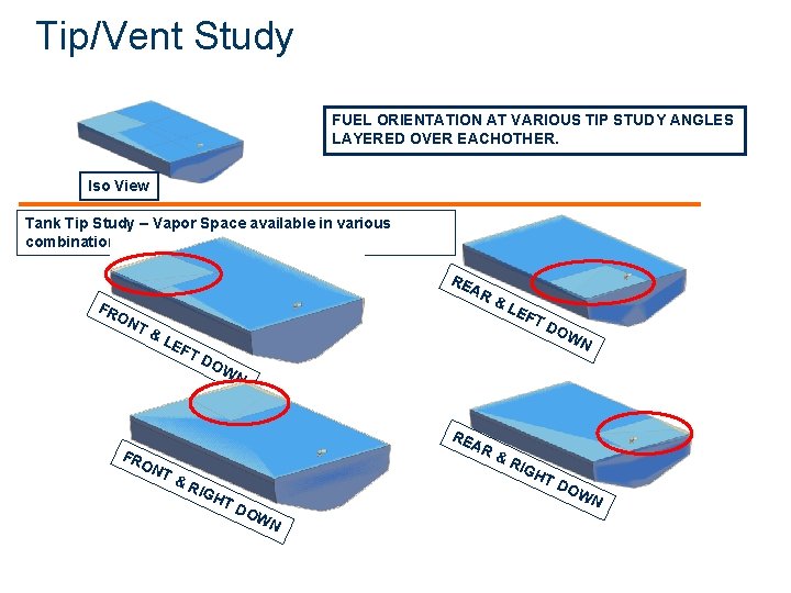
Tip/Vent Study FUEL ORIENTATION AT VARIOUS TIP STUDY ANGLES LAYERED OVER EACHOTHER. Iso View Tank Tip Study – Vapor Space available in various combinations FR RE AR & ON T& LE FT DO AR ON T& FT DO WN WN RE FR LE RIG HT D OW N &R IGH TD OW N
Venting Considerations • How does my fuel system create ullage? • How does my system allow for venting at ABYC H 24 angles? • What happens at angles beyond H 24? • How do I prove that my fleet vents safely for every model?
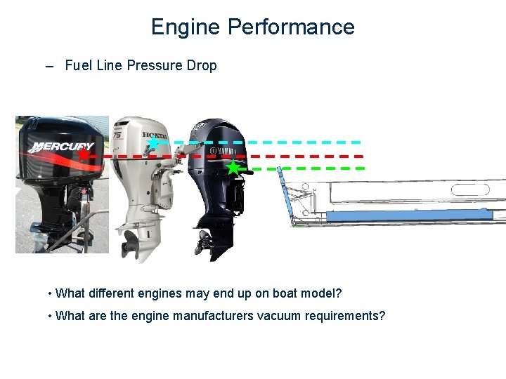
Engine Performance – Fuel Line Pressure Drop • What different engines may end up on boat model? • What are the engine manufacturers vacuum requirements?
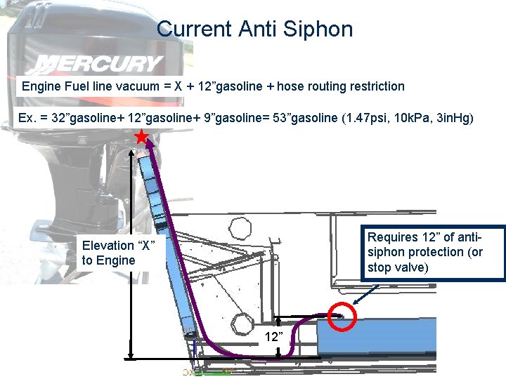
Current Anti Siphon Engine Fuel line vacuum = X + 12”gasoline + hose routing restriction Ex. = 32”gasoline+ 12”gasoline+ 9”gasoline= 53”gasoline (1. 47 psi, 10 k. Pa, 3 in. Hg) Requires 12” of antisiphon protection (or stop valve) Elevation “X” to Engine 12”
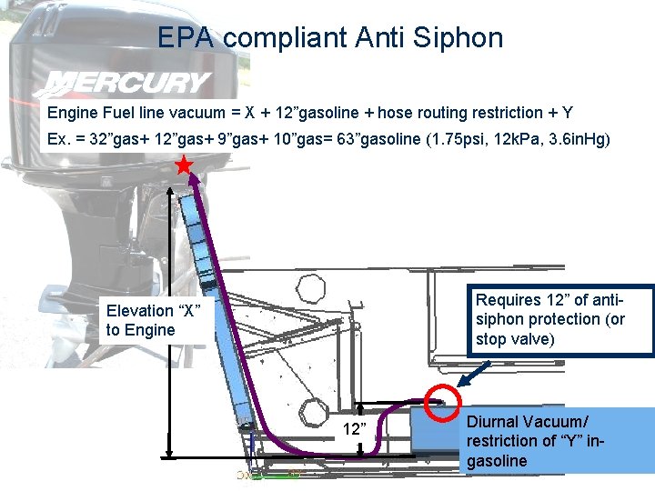
EPA compliant Anti Siphon Engine Fuel line vacuum = X + 12”gasoline + hose routing restriction + Y Ex. = 32”gas+ 12”gas+ 9”gas+ 10”gas= 63”gasoline (1. 75 psi, 12 k. Pa, 3. 6 in. Hg) Requires 12” of antisiphon protection (or stop valve) Elevation “X” to Engine 12” Diurnal Vacuum/ restriction of “Y” ingasoline
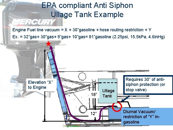
EPA compliant Anti Siphon Ullage Tank Example Engine Fuel line vacuum = X + 30”gasoline + hose routing restriction + Y Ex. = 32”gas+ 30”gas+ 9”gas+ 10”gas= 81”gasoline (2. 25 psi, 15. 5 k. Pa, 4. 6 in. Hg) Elevation “X” to Engine 18” 12” Ullage Tank Requires 30” of antisiphon protection (or stop valve) Diurnal Vacuum/ restriction of “Y” ingasoline
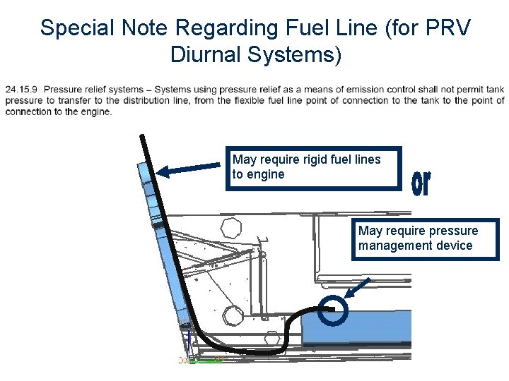
Special Note Regarding Fuel Line (for PRV Diurnal Systems) May require rigid fuel lines to engine May require pressure management device
Engine considerations • What different engines may end up on boat model? • What are the engine manufacturers vacuum requirements? • What is elevation of engine hook ups? • Do I have sufficient pressure drop budget for the EPA Diurnal system I want? • What is the tank vacuum with EPA diurnal system? • What is the additional fuel pressure drop with EPA diurnal system?
Safety Considerations • What is preventing over pressurization of the tank? • What safety methods and strategies prevent fuel from entering into the bilge? • What happens when a customer fills a tank in an extreme circumstance beyond ABYC & EPA specifications? (i. e. 65°F temperature swing) • Will the new fuel systems allow engines to operate properly under all conditions? • Is there a single component that can cause system to fail or is there redundancy built in?
Technical Considerations 1) Refueling with no spit-back 2) Engine fuel line pressure drop 3) Hot Fuel Handling 4) Extreme Vessel angles/ attitudes 5) Jerry Can filling event 6) Non-automatic nozzle filling event 7) Vapor Condensation/ liquid accumulation 8) Expected CARB requirements 9) Pressure Lifecycle 10) Fill Level Repeatability 22
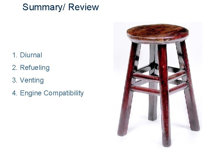
Summary/ Review 1. Diurnal 2. Refueling 3. Venting 4. Engine Compatibility 23

Questions? 24
Appendix 25
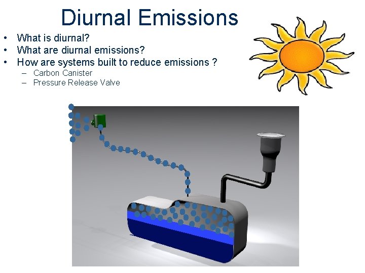
Diurnal Emissions • What is diurnal? • What are diurnal emissions? • How are systems built to reduce emissions ? – Carbon Canister – Pressure Release Valve
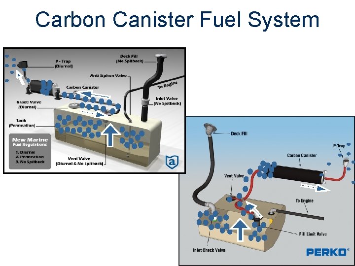
Carbon Canister Fuel System
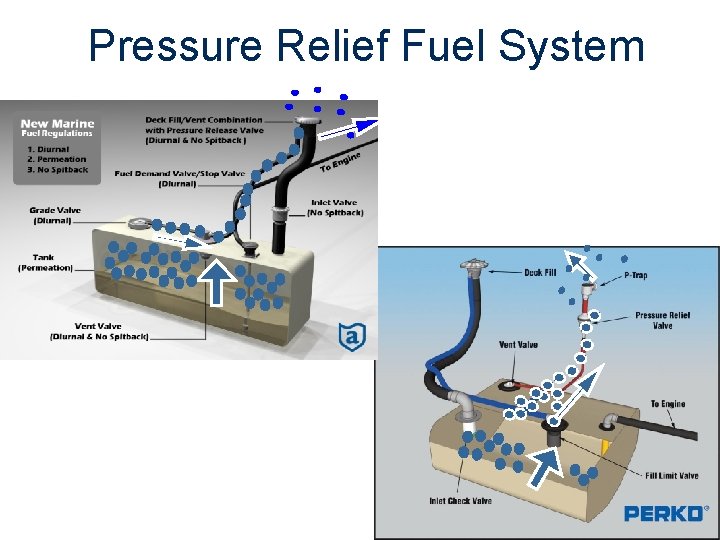
Pressure Relief Fuel System
- Slides: 28