Fuel element FE Heatemitting element Nuclear fuel fuel
 Heat-emitting element • Nuclear fuel - fuel assemblies (FA), consisting of")


 of the VVER-1000 reactor")


 reactor")
 • The system")


 The reactor control system is not only")
 is a structure that unites")


 of the reactor is designed: •")


;")

 • The range of")
 • It is mainly intended")


- Slides: 47
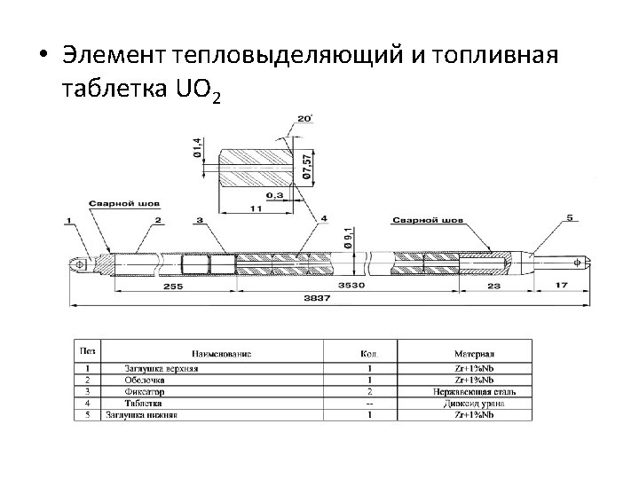
Fuel element (FE) Heat-emitting element • Nuclear fuel - fuel assemblies (FA), consisting of fuel elements (fuel elements) containing tablets from uranium dioxide, slightly enriched in 235 th isotope. • The fuel element (FE) is a sealed tube of zirconium doped with niobium to increase ductility.
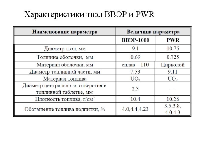
• The melting point of the material is about 1900 ° C, at a temperature above 350 ° C the strength properties deteriorate. • The thickness of the shell is 0. 65 mm, • outer diameter of the tube is 9. 1 mm. • The length of the fuel element is 3800 mm, the mass is 2. 1 kg. • Inside are uranium tablets and a spring in the upper part, which compensates for their thermal displacements.
• The pellet contains tablets of uranium dioxide with a density of 10. 4 -10. 6 g / cm³, • each with an outside diameter of 7. 57 mm and a height of 20 mm. • In the middle of the tablet there is a hole 1. 2 -1. 4 mm in diameter, the edges are chamfered. • The gap between the tablet and the cladding, as well as the central opening, is designed to increase the tablet as a result of radiation swelling.
• The total length of the column of tablets is 3530 mm (at the capacity of 30 mm). • Tablets occupy 70% of the space inside the fuel element, the rest of the space is occupied by gases. • In the manufacture of fuel elements, helium is injected to a pressure of 20 -25 kgf / cm², • In the process of operation, gaseous fission products are added to it (the pressure increases to 50 -80 kgf / cm 2). • When working at power, the average temperature in the center of the tablets is 15001600 ° C, on the surface - about 470 ° C.
• As the shell material, the zirconium alloy E 110 was used with 1% niobium. • An important improvement was the use of a burnishing absorber, gadolinium oxide, introduced directly into the fuel matrix • They allow to reduce the excessive reactivity of fresh fuel with high enrichment
6
9
• he non-fluid fuel assemblies used in VVER 1000 are hexagonal. • The length of the assembly is about 4. 5 m, weight - 760 kg, volume - 80 liters, size "turnkey" - 234 mm. • Their total number in the core is 163. • Each consists of 312 fuel rods and has 18 tubular channels to enter the working elements of the control system. • The step of placing the fuel rods is 12. 75 mm.
• The nominal water flow through each fuel assembly is about 500 m³ / h, • its average speed is 5. 6 m / s. • Each hydraulic turbine is powered by a hydraulic ejection force of approximately 450 kg.
• The main part of the fuel assemblies consists of a bundle of fuel rods, each of which is fixed in the lower part to the shank of the fuel assemblies. • Above the bundle of elements through the springs rests against the head, the maximum travel of the springs is 22 mm. • The frame structure is 18 tubular channel guides and 12 -15 spacing grids.
Central tube with in-core measuring sensors. • All intra-reactor sensors are assembled into measuring probes, which are installed in the central tubes of TVS in the amount of 64 pieces. They contain 7 sensors of neutron flux (with a long emitter not exceeding 50 mm), input and output low-inertia thermocouples.
• All FAs are equipped with channels for regulators, but there are only 61 clusters (fuel assemblies - 163). • Rods are a thin-walled tube made of zirconium with a diameter of 8. 2 mm, with a column height of absorbing material of 3740 mm, • in the quality of which boron carbide is used.
• Each regulating organ contains 18 rod absorbing elements which are integrated constructively by means of a gripper head, otherwise called a traverse. • As a structural element, the cluster head is a central bushing, from which cantilevered ribs with holes for installation of PEL rods leave.
• Each absorbing member is a sealed shell in the form of a rod consisting of a stainless tube • (internal diameter 7 mm, external - 8. 2 mm, wall thickness 0. 6 mm), • which is filled with a material that absorbs neutrons well.
• The cluster (control organ) of the VVER-1000 reactor
• A general view of an absorbent member comprising an absorbent material of boron carbide
• Location of regulatory bodies 19
• For the convenience of management, the PRs are grouped into 10 groups, one of which is used for operational regulation, • 9 others - as an emergency protection and the solution of some specific problems, for example, suppression of xenon oscillations. • The velocity of the groups is 20 mm / s (<0. 02 $/c). • The rate of fall is 1 -1. 2 m / s.
Emergency protection equipment • Emergency protection ensures the termination of the fission chain reaction in the reactor in the event of an emergency situation. • At the signal of the “emergency protection”, the drives are de-energized and the control relay drops into the active zone within 4 seconds. • The effectiveness of “emergency protection” is 5%.
• Preventive protection system. • The system of the ( «ПЗ» ) reactor is designed: • «ПЗ-1» -I for unloading the reactor by acting on the control group of the control system with deviation of the parameters beyond the established limits; • «ПЗ-2» to prohibit unloading of the reactor if the parameters deviate beyond specified limits. • Under the action of the «ПЗ-1» signal, the control group of the control system is entered at operating speed. • Actions of the «ПЗ-1» operator can be duplicated by a key.
• The system of accelerated unit unloading ( «УРБ» ) • The system is designed for rapid discharge of the reactor in the following cases: • switching-off of 2 Main circulation pumps from four working and neutron power more than 75% of the nominal. • When the BDS is operating, the 1 st group of the control system falls. • Correction of the reactor power to the set power values is carried out by the POM - power limiting regulator. • The operator can duplicate the BDS with a key.
• CONTROL SYSTEM • The source of information about the state of the reactor are the ionization chambers measuring the neutron flux. • In order to ensure the fulfillment of all the tasks assigned to the management system, the system as a whole is executed according to the principle • multichannel construction of the measuring part, • multichannel information processing with channel health monitoring and the use of reliable reliability criteria • and power backup of all systems.
• The control system monitors the reactor power according to the signals of the IR (ionization chambers), the proportionality of the current to which the neutron flux is provided by the characteristics of the IR and measurement channels as a whole. • The IR signals entering the control system are adjusted to match thermal capacity of the reactor installation. • In a generalized form, the structure of the control systems • includes • The measuring part, • logical part, • electromechanical part (control systems and rod position indicators).
• Сontrol and protection system (СPS) The reactor control system is not only a system that is important for safety, • but also - the main system of operational support of nuclear safety along with the system of liquid regulation.
• The system of control and regulation (CPS) is a structure that unites • object of control (OS) and special technical means in technologically organized feedback (OS), to which the control object (OS) is covered. • This feedback is intended in the management process to correct those natural feedbacks that the reactor possesses as a physical object.
• Due to the continuous measurement of the reactor period (which is an indicator of the rate of change in power) • and comparing the measured value with the setpoint, • control signals are generated for the movement of the control system in the event of a deviation in the rate of change in the power of the reactor (in transient regimes) • from the permissible value determined by the operating procedure.
• The power settings can be changed in an orderly manner as the power of the switchgear changes and depending on the parameters of the second circuit. • The main purpose of CPS is in providing nuclear safety of the reactor and regulating its capacity.
• The control system and protection (CPS) of the reactor is designed: • - for the launch of a nuclear reactor and its output for power; • - for operational maneuvers with the capacity of the reactor and stabilizing it at a given level; • - for operative regulation of reactor power in accordance with a given power;
• - to compensate for slow changes in the reactivity margin; • - for the constant issuance of information on the position of each regulatory body in the control computing system and the information and computer complex of the SVRC; • - for emergency protection of a nuclear reactor against a nuclear threat.
• VVER-1000 reactor control and protection system • The hardware part of the VVER-1000 CPS consists of the following functional subsystems: • Subsystem of extra-zonal neutron detectors (ND); • The subsystem of neutron flux monitoring equipment;
• a subsystem of emergency and preventive protection ( «AЗ» and «ПЗ» ); subsystem of automatic power controller ( «APМ» ); • subsystem of the device for unloading and power limitation ( «РOM» ); • subsystem of accelerated block unloading ( «УРБ» ); • subsystem of group and individual management; • a subsystem for diagnosing the operation of the control system.
• The mechanical part of the VVER-1000. Consists of the following functional subsystems: • subsystem of electromagnetic stepper drives; • subsystem of regulatory authorities ( «ОР» ); • subsystem of monitoring the spatial position of regulatory bodies.
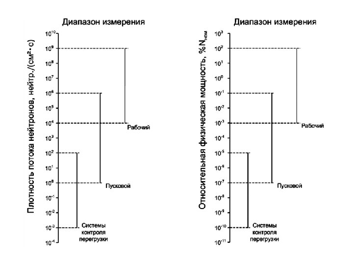
• Ranges of neutron flux density measurements (reactor power) • The range of neutron flux density measurement is divided into subbands: • - Intermediate range ( «ДП» ); • - Energy range, or working ( «ДЭ» , «ДР» ). • These ranges are conditional and overlap
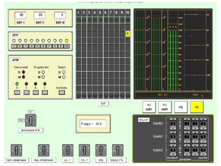
• Automatic reactor power regulator ( «АРМ» ) • It is mainly intended for stabilizing the reactor power at a given level and bringing the reactor power in line with the power of the turbogenerator
• The main technical task of AWS is to free the operator from constant routine monitoring of changes in neutron power or pressure in the main steam manifold. • And also to ensure the correct transition process in unforeseen situations associated with a sudden change in operating modes.
• In the automatic control mode according to APM signals, control is carried out only by groups. • During the control signal, the buzzer sounds for movement of the OP group.
part of the first nuclear reactor loop 43
• Fig. 1 shows configurations of the core and fuel assemblies of VVER-1000 reactor. • Core (163 FA) FA (312 FE)
• Fig. 2 shows configurations of the core and fuel assemblies of PWR for Gösgen NPP located in Sweden. • Core (177 FA) FA (205 FE)
Structural characteristics of VVER and PWR core Name of the parameter Total number of FA in the core, items Value of the parameter VVER PWR 163 177 Number of FA with аbsorbing rods of control and protection systems, items 61 49 Number of FA with burnable poison rods (for 3 year old core and core of the 1 st year) Height of heated part (in cold state), m 54 - 3. 53 3. 55 Pitch between fuel assemblies, m 0. 236 0. 215 Flow section of the core in the heated part, m 2 Coolant flow through the core, kg/s 4. 17 4. 41 17650 15984 Reactor heating capacity, MW 3000 46
• Characteristics of FA for PWR and VVER Name of the parameter Pitch of the same size as the wrench, mm Fuel assembly pitch, mm Number of fuel assemblies, items Number of tubes for absorbing elements, items Number of tubes for neutron measurement channel, items Length of the active part of fuel element, mm Number of distance grids, item Material of the grid Value of the parameter VVER-1000 VVER 234 215. 6 12. 75 312 14. 30 205 18 20 1 1 3530 (3550) 3550 (3564) 14 (12) 6 Steel (Zirconium) Zirconium 47