AnNajah National University Faculty of Engineering Civil Engineering


 FOR BLOCK A")


")


")


IN BLOCK C Mat 1 plan Mat 1 displacement")
 in x-axis")


- Slides: 61
An-Najah National University Faculty of Engineering Civil Engineering Department Terra Santa School Structural Design and Analysis Prepared By: Bara Shawahna Khaled Malhis Nadeem AL-Masri Supervised By : Dr. Mahmud Dwaikat
OUTLINE q Introduction & general description of the project q 3 D modeling q Shear walls design q Design of columns q Design of beams q Slabs design q Foundation design
INTRODUCTION Our Graduation project is the design of a school in Jericho named as Terra Santa School. This school was designed by Al-Diyar Consultant and we will check on their design. The school consists of three floors with total plan area of (3866. 5 m 2).
Scope of work
Methodology SAP 2000 program will be used as main analysis tool. ACI 318 -08 for design. Live loads are taken from ASCE 7 -05 code. UBC 97 for seismic design.
MATERIALS USED IN THE PROJECT:
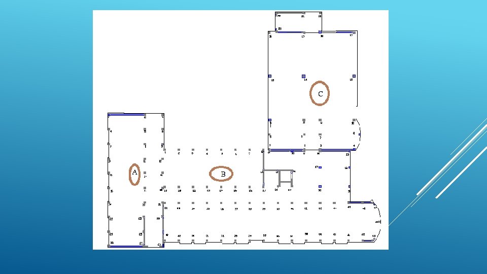
STRUCTURAL SYSTEMS For each block we chose the following floor system: 1. Block A ( one way ribs slab ) 2. Block B ( one way ribs slab ) 3. Block C ( two way ribs slab ) Blocks A & B. It’s very clear to see that block A , B has a uniform grid for columns with clear path of loading (one-way), therefore, we took the architectural layout for the columns. Ribbed slabs are known for their economic efficiency. The thickness calculation follows the ACI-318 code Block C has a different shape and dimensions and according to ACI – code requirements the slab should be designed as two-way ribbed slab for economic and deflection requirements. This is because the spans of each panel in Block C have approximately equal lengths.
LOADS Dead load: Own weight for one way slabs = 3. 54 k. N/m 2. Own weight for two way slabs = 4. 86 k. N/m 2. Super imposed load = 3 k. N/m 2. Live load: for all the class room = 2 KN/m 2. for corridors = 5 KN/m 2.
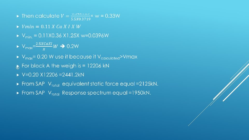
ANALYSIS AND DESIGN AGAINST SEISMIC LOADS We will design the seismic load by using SAP 2000. Several methods is used in SAP for seismic which is: Dynamic analysis: 1. Response spectrum. 2. Time history. Equivalent static force Equivalent static method will be used for comparison [Block A only] and as a cross-check on the results of response spectrum analysis. Because response spectrum is more realistic and covers the modal shapes of the building, we will use it as a main tool for seismic design.
The seismic force effect on the structure can be translated to equivalent lateral force at the base of the structure and then this force will be distributed to the different stories and then to the vertical structural elements (frames and/ or shear walls). This method is best applied to Regular Structure only.
DESIGN FOR EARTHQUAKE BY EQUIVALENT LATERAL FORCE METHOD (STATIC METHOD) FOR BLOCK A
SEISMIC ZONE FACTOR Z From this map the project in Jericho Z = 0. 3
CV AND CA TABLE Soil type D CV=0. 54 Soil type D Ca=0. 36
IMPORTANCE FACTOR TABLE I = 1. 25
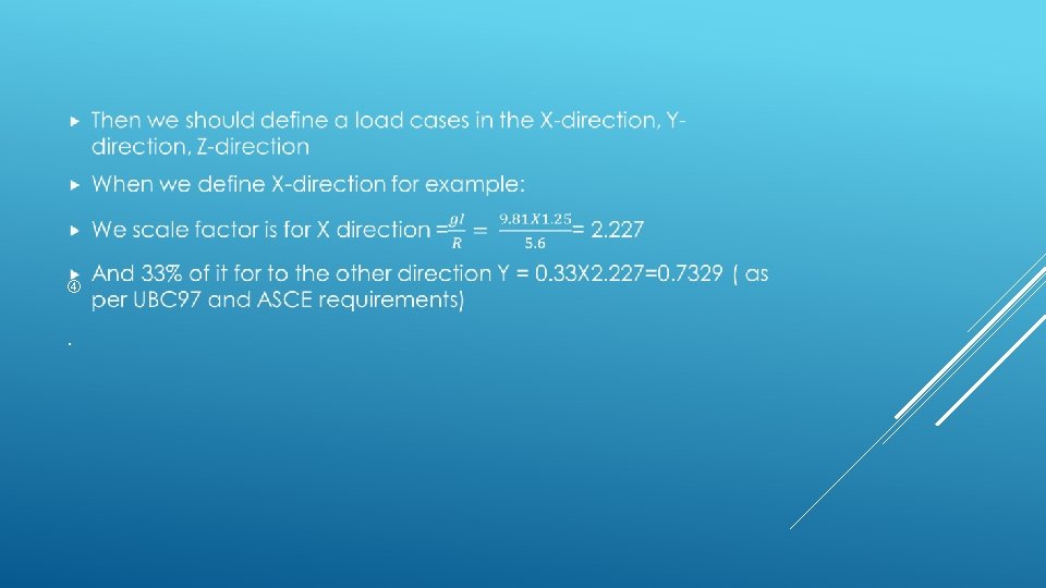
RESPONSE MODIFICATION FACTOR “R” TABLE The overall system is dual system R for building between (4. 2 -6) =5. 6
T CALCULATION
RESPONSE SPECTRUM METHOD We use sap to design and analyze the project the design response spectrum is shown in
We find CA=0. 36, CV=0. 54 Then we have this curve
3 D MODELING STRUCTURE OVERVIEW
BLOCK B
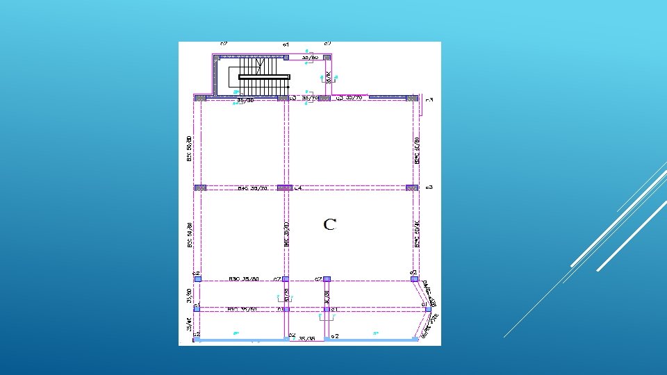
BLOCK C
COMPATIBILITY CHECK
EQUILIBRIUM CHECK FOR BLOCK A Dead load: 1. Slab dead load = area X slab own weight per square meter =1185. 84 X 3. 54=4136. 4 k. N 2. Shear wall load = walls volume X concrete weight per volume = 28. 7 X 0. 3 X 15 X 25=3288. 75 k. N 3. Columns dead load = column volume X concrete weight per volume = 30 X 15 X 0. 4 X 25=1800 k. N 4. Beams dead load = beams volume X concrete weight per volume = 3691. 4 k. N 5. Total dead load = 12917. 6 k. N 6. Total dead load form SAP = 12956. 699 7. % Error = 0. 3% which is acceptable
Live load: Structure area X live load per square meter =1185. 84 X 5 =5929. 2 k. N Live load from SAP = 5929. 2 k. N % Error = 0 Superimposed dead load: Structure area X superimposed load per square meter = 1185. 84 X 4. 5 = 5336. 28 k. N Superimposed load from SAP = 5336. 2 k. N % Error = 0
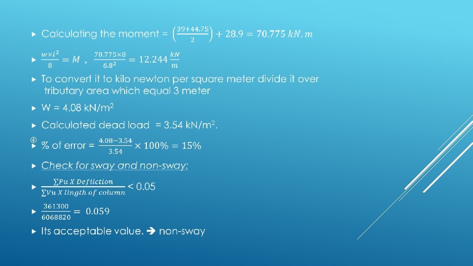
MOMENT EQUILIBRIUM CHECK We take block A as example to do this check. In this check we take the moment from 3 D modeling and find the weight and then comparing it with the hand calculated weight Moment resulted from dead load in block A in beam B 1 is:
DESIGN OF SHEAR WALLS
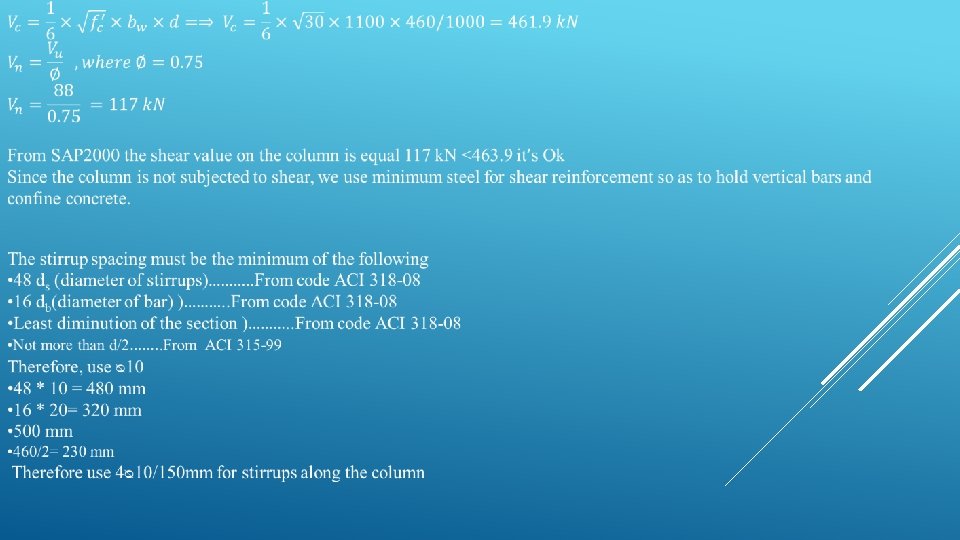
DESIGN OF COLUMNS
DESIGN OF THE COLUMNS AGAINST SEISMIC LOAD
From SAP 2000 and 3 D-model we take Pu=8287 and it equal ��Pn then we go to the interaction diagram and take the steel ratio value= 0. 012 ��Pn/bh=15 ¥=h-2 couver/h = 0. 9 Mu/bh 2=1. 44 = 0. 2 ksi =2. 15 ksi
Column Dimension Main Steel Stirrups C 1 40 X 40=1600 8ᴓ 20 1ᴓ 10/150 mm C 2 50 X 50=2500 12ᴓ 18 3ᴓ 10/150 mm C 3 85 X 50=4250 18ᴓ 18 3ᴓ 10/150 mm C 4 110 X 50=5500 28ᴓ 18 4ᴓ 10/150 mm
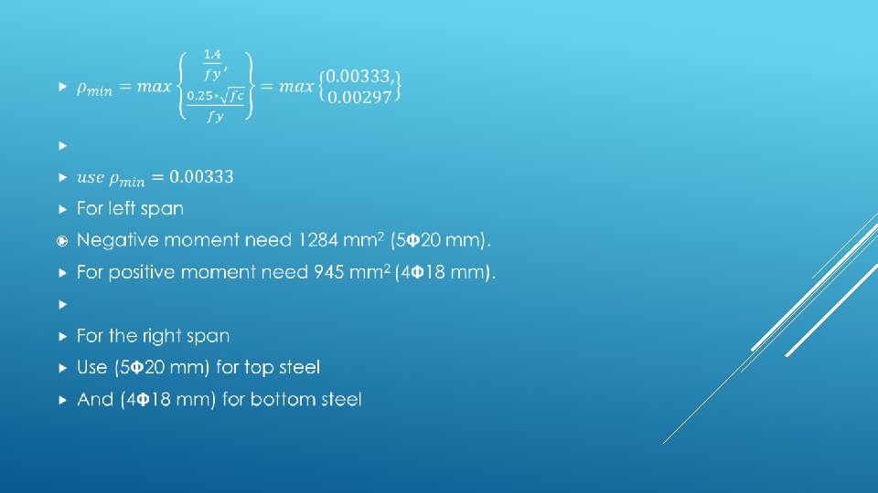
DESIGN OF BEAMS Beam distribution and categories
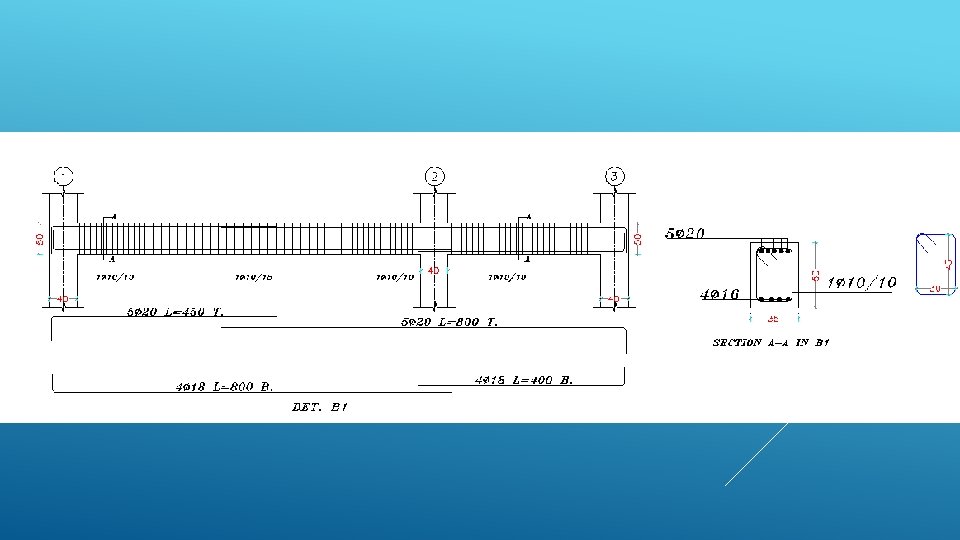
FOR BEAM B 1 AT BLOCK A UNDER SEISMIC LOAD (50 X 35 CM)
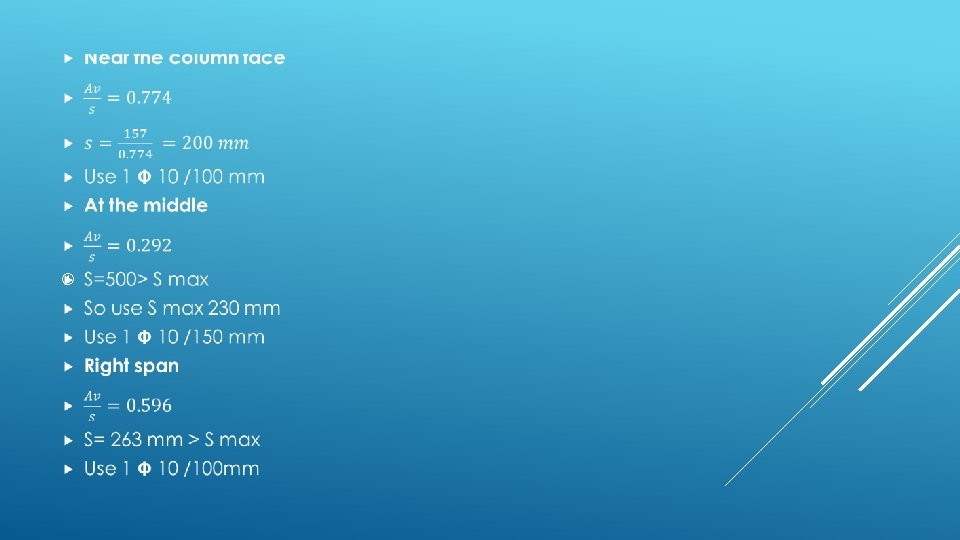
DESIGN FOR SHEAR
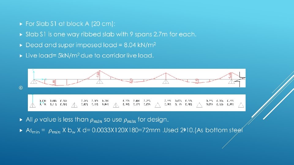
SLAB DESIGN The maximum span length is about 2. 7 m as shown in Block A, B Map, and therefore thickness of the slab (assumed one-way ribbed) according to the table will be L /18. 5 =15 cm and we used 20 cm for block A& B(S 1).
The maximum span length is about 7. 55 m as shown in Block C Map, and therefore thickness of the slab two-way ribbed according to the table will be Ln /30 =25. 1 cm and we used 30 cm.
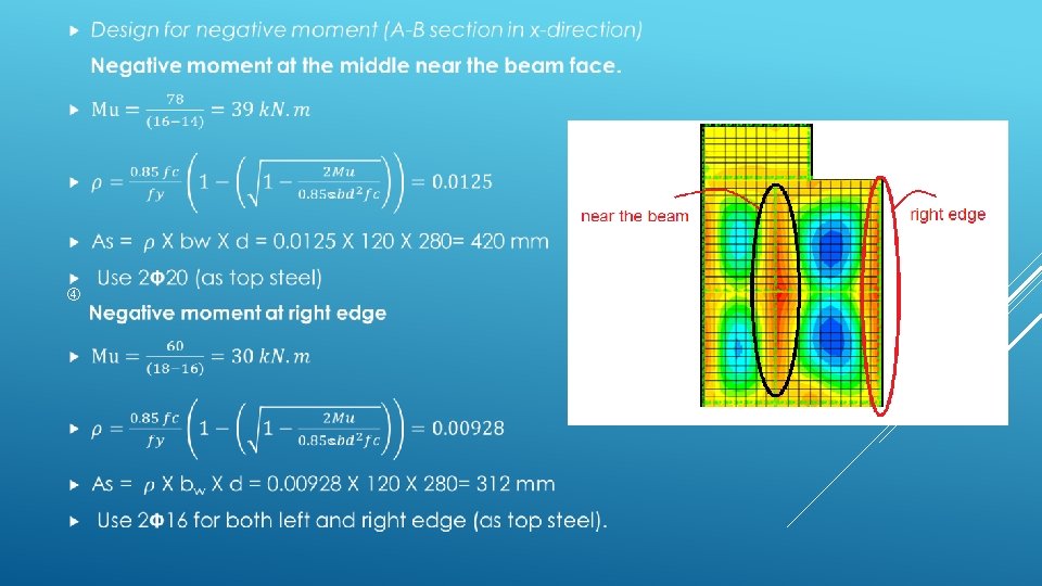
DESIGN FOR TWO WAY RIBBED SLAB IN BLOCK C m 11 (x-direction moment)
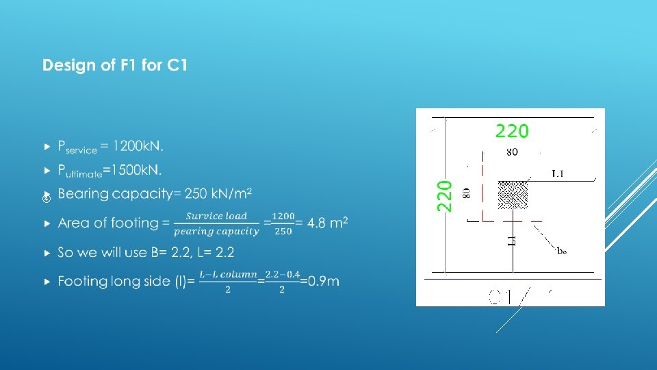
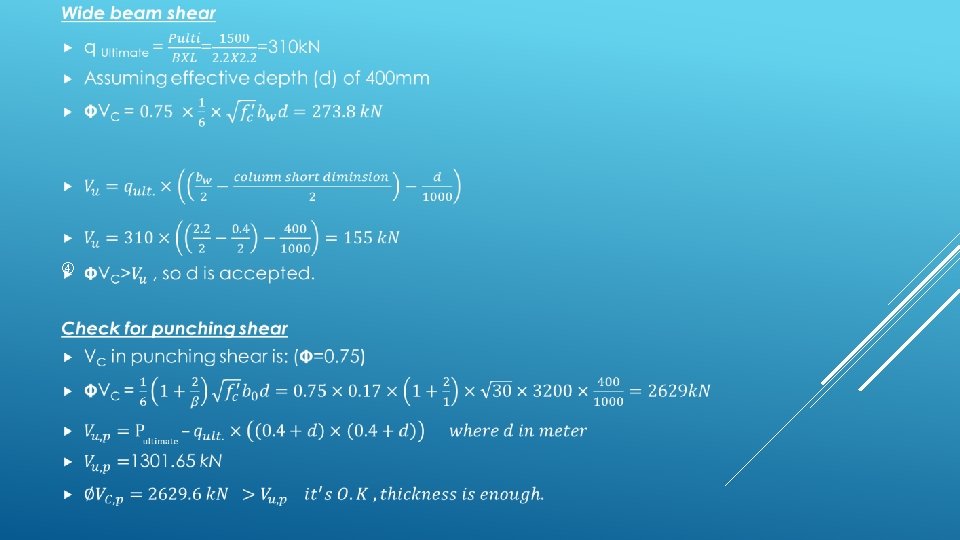
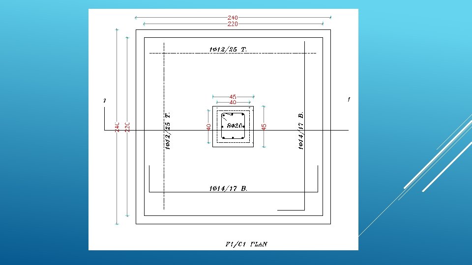
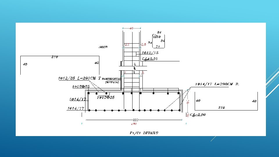
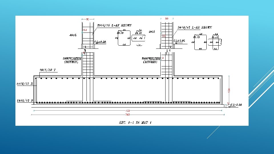
Foundation
footing number F 1 F 2 F 3 F 4 p service 1200 2860 4000 6200 p ultimate 1500 3720 5227 8245 footing area 4. 8 11. 44 16 24. 8 b l d As As, min 2. 2 3. 5 4 5 400 500 600 900 843 1862 2273 2507 864 1044 1224 1764
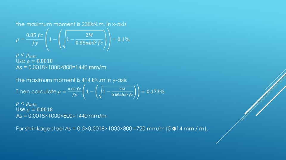
DESIGN OF MAT (1)IN BLOCK C Mat 1 plan Mat 1 displacement
moment (m 11) in x-axis
C 2 C 1
THANK YOU