AnNajah National University Faculty of Engineering Civil Engineering


 :")
")
")
:")

 Yielding strength")


 : The structure has a period T =0. 477 seconds")
 : 1 KN/m 2 load applied over")


 bars Negative")
 for shear: An-najah National university")
 for shear: An-najah National university")

: An-najah National university")


 An-najah National university")


- Slides: 72
An-Najah National University Faculty of Engineering Civil Engineering Department Three Dimensional Design of Al-sakhl Residential Building Under Gravity and Seismic Loads Prepared by: Abdulkarim Ghozzi Ali Sawalha Anas Alawneh Mohammad Yaseen Supervisor: Dr. Mahmoud Dweikat.
Introduction. Review of 3 D Modeling Seismic Analysis Final design and details
Project description � � The building is located in Rafedia-Nablus The building consists of 8 floors, of which 2 are underground basement floors. The total floor areas of the building are 4786 m 2. It has two parts separated by a construction joint.
Ø Basement 2 floor (Residential apartments) :
Ø Basement 1 Floor ( Parking )
Ø Ground floor (commercial stores)
Ø Repeated floor (Residential apartments):
Ø Assumptions for Design: 8 12
Ø Structural Materials: üReinforced concrete ü Steel (Rebar, shrinkage mesh and stirrups) Yielding strength (Fy) = 420 MPa. Modulus of elasticity (Es) = 200 GPa 13
Ø Non-Structural Materials:
Ø Load Assumptions: 11 16
Ø Soil Property ü Allowable bearing capacity of soil=250 KN/m² ü Surcharge Load is assumed to be 20 KN/m² ü Unit weight of soil (�����) = 18 KN/m 3 15
Ø 3 D Model 52
ØSlab modifiers One Way Ribbed Slab An-najah National university One Way Solid Slab 14
Also, for beams , columns and shear walls the modifiers are as follows: Beams: v. Torsional constant: 0. 35 v. Moment of inertia about 2 axis: 0. 35 v. Moment of inertia about 3 axis: 0. 35 Columns: v. Torsional constant: 0. 7 v. Moment of inertia about 2 axis: 0. 7 v. Moment of inertia about 3 axis: 0. 7 Shear Walls: v. Torsional constant: 0. 7 v. Moment of inertia about 2 axis: 0. 7 v. Moment of inertia about 3 axis: 0. 7 An-najah National university 15
Checks Compatibility: 65
Equilibrium:
Stress strain relationship check Check slab Check Beam Check Column 68
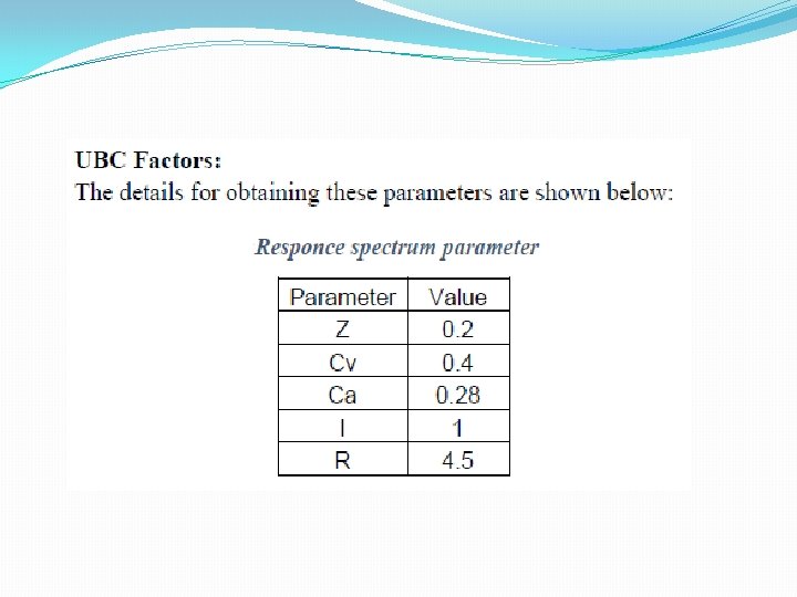
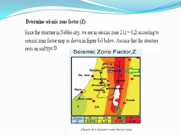
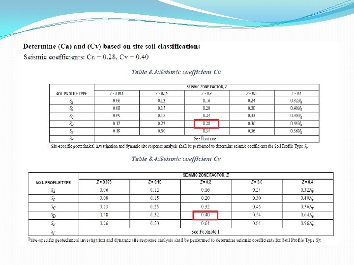
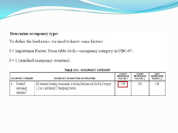
ØDynamic Analysis q UBC 97 code q Response spectrum analysis method An-najah National university 17
Ø Check Period (T) : The structure has a period T =0. 477 seconds T = 0. 48 sec T method A :
Determine response modification factor ( R ) : 1 KN/m 2 load applied over the area. X-Direction : Total reaction for shear wall = 1732. 4 KN …………. >75% Total reaction for column = 448. 88 KN Total reaction = 2181. 26 KN Also in Y-direction …… >75% To decide the type of wall we checked the axial stress: 0. 06 * 28 = 1. 68 Mpa Stresses > 1. 68 Mpa , then bearing wall
27
Ø Modal case:
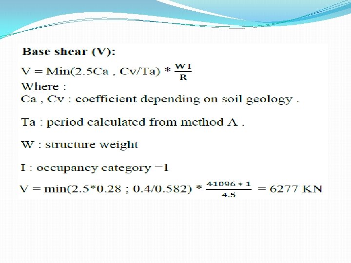
Using response spectrum to determine the design base shear:
Ø Define Response in ETABS program
Ø Define load cases
ØDefine load cases
35
Ø Load combinations
ØCheck Drift : 37
Ø Design of structural elements Slabs Beams Columns
Design of slabs The structural system for the basement one is one way solid slab(20 cm) with drop beams. Solid slab in block B, story 2. An-najah National university 52
ØAnalysis and Design for flexure An-najah National university 56
For positive moment. The values of M 22 for the story two An-najah National university 41
For negative moment. 56
For negative moment. An-najah National university 43
For negative moment. An-najah National university 44
zone # Moment sign Bar 1, 2 - ve moment 1ɸ 12/200 mm 3, 4 - ve moment 1ɸ 10/160 mm other - ve moment 1ɸ 10/200 mm An-najah National university 45
58
Ø Design Of Beams Ø Final output was taken from 3 -D model. The following figure shows the final locations and layout of beams in the repeated floor Beams must be designed against moment and shear. The values for these forces are obtained from 3 D model An-najah National university
ØAnalysis and Design for flexure and shear Design for flexure: An-najah National university
ØAnalysis and Design for flexure An-najah National university 56
ØAnalysis and Design for flexure An-najah National university 56
ØAnalysis and Design for flexure An-najah National university 56
Design for flexure: Longitudinal reinforcement for B 5 location As (mm 2) bars Negative – Left 686 5Ø 14 B 5 Positive 686 5Ø 14 Negative -Right 1626 7Ø 18 An-najah National university
Design beam (B 5) for shear: An-najah National university
Design beam (B 5) for shear: An-najah National university
Seismic requirement: An-najah National university
ETABS design result for this beam (B 5): An-najah National university
Design of columns An-najah National university
Sway –Non sway Check In the X-direction: In the Y-direction: Slenderness Check Take Column in block B An-najah National university
Designing the Column under axial force and moment: The Ultimate forces on the column: Pu= 2351 KN. Mu= 59 KN. m < Mmin= Pu (0. 015+0. 03 h) = 2351 * (0. 015 + (0. 03*0. 8)) = 91. 69 KN. m Use M = 91. 69 KN. m An-najah National university
An-najah National university
by using the interaction diagrams: Now: ρ = 0. 01 As = 0. 01 * 800 * 300 = 2400 mm 2. As from ETABS = 2400 mm 2. . An-najah National university
Seismic requirement: So = Min { 300/2 = 150 8*14 =112 24*10 = 240 300 } So = 112 mm use So = 110 mm S 1 = Min { 300 16*14 = 224 48*10 = 480 } S 1 = 224 mm use S 1 = 220 mm lo = Max {800 ((3250 -320=2930) /5) = 586 } lo = 800 mm An-najah National university
A longitudinal section in column (C 3) An-najah National university
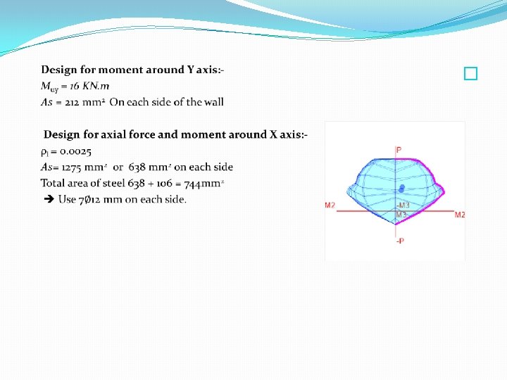
Design of shear wall �
Design of mat footing Thickness = 1000 mm Checks: Check stress under mat foundation: 2 �� allowable = − 250 k. N/m 2 �� maximum = − 162 k. N/m 2 �� minimum = − 5 k. N/m
Check punching shear for mat foundation: Ultimate punching shear-to-punching shear capacity ratios
Reinforcement of Footings
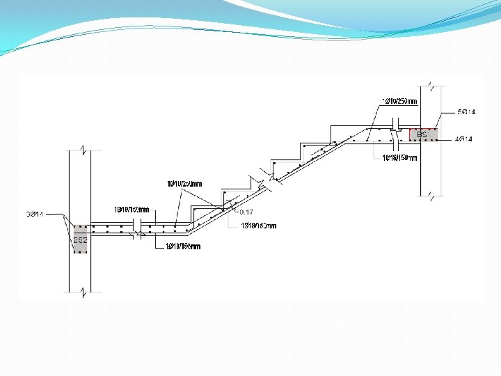
Design of stairs Own weight = 6 KN/m SID = 4 KN/m Live = 5 KN/m Vu = 55. 4 KN ɸ Vc = 86 KN OK Mu = 73 KN. m Use 1 Ø 18 / 150 mm
120