AnNajah National University Faculty of Engineering Civil Engineering


 Rectangular Combined Footing b) Trapezoidal Combined footing c)")
 The radial")

.")

 � Atterberg")
 Plasticity Index (m) Content")
 Cohesion (Kg/cm 2) Angle of internal Friction Ф(ο) 1 0.")


 L (m) provide area F")


 L (m) d (cm) h")


- Slides: 36
An-Najah National University Faculty of Engineering Civil Engineering Department Zara Center New Building Footing Design Prepared by Mohammad Samaaneh Supervisor Dr. Sami Hijjawi
Chapters Chapter One : Introduction Chapter Two : Literature Review Chapter Three : Site Investigation & Soil report Chapter Four : Design of Foundations Chapter Five : References & Appendices
Chapter One : Introduction � Project title : Zara center � Nablus – Palestine � A multistory building lies to the south of Rafidia street in Nablus city , this building consist of seven stories , and described as commercial building. � This graduation project deals with the following main topics: � � Selection of foundation type. Geotechnical and structural design of footing alternatives.
General Requirement for footing �Footing area must be able to carry load and transfer it safely to the soil. �Footing must be able to prevent structure movement, sliding and overturning. �Footing settlement and differential settlement must be acceptable for footing and total structure. � Structure safety must be first.
Chapter Two : Literature Review Soil Mechanics � Types of soil � Specification of soil � Shear Strength of soil � Soil compaction � Slope stability � Soil settlement (compressibility of soil) � Site investigation
Foundations Isolated Footings Combined Footings a) Rectangular Combined Footing b) Trapezoidal Combined footing c) Strap or Cantilever Footing Mat or Raft Foundations Pile foundations Settlements of Foundations
Load Transfer �The triangle zone ACD immediately under the foundation. � 2) The radial shear zones ADF and CDE, with the curves DE and DF being arcs of logarithmic spiral. � 3) Two triangular Rankine passive zones AFH and CEG
Chapter Three Site Investigation & Soil Report �The geotechnical conditions of the site were studied through comprehensive site investigation, carried out on August – 2007 by Hijjawi Construction Labs.
The purpose of site investigation �Determine the type of foundation required (shallow or deep). �Make a recommendation on the allowable bearing capacity of the soil. �Location of the groundwater level. �Identification and solution of excavation problems
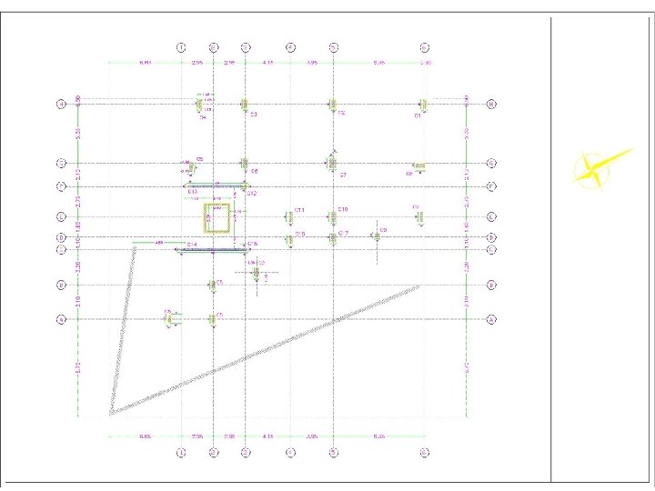
Boreholes
LABORATORY TESTING � Natural moisture contents � Grain size distribution (sieve analysis) � Atterberg limits (Liquid and Plastic) � Direct shear test
Results Borehole Depth Moisture % passing sieve Liquid limit (%) Plasticity Index (m) Content (%) #200 0. 00 – 2. 5 8. 5 68. 3 42. 4 13. 27 2. 5 - 9. 0 10. 9 66. 5 44. 3 14. 36 0. 0 – 4. 6 12. 1 52. 5 47. 6 14. 83 4. 6 – 9. 0 12. 8 59. 6 42. 8 11. 34 0. 0 – 1. 0 7. 9 43. 8 25. 6 8. 79 1. 0 – 14. 0 10. 9 63. 7 43. 1 12. 16 (PI) No. 1 2 3 Summary of test results
Borehole No. Elevation (m) Cohesion (Kg/cm 2) Angle of internal Friction Ф(ο) 1 0. 5 31 26 2 1. 0 28 24 3 0. 5 20 28 Summary of shear test results
Allowable Bearing Capacity The recommended bearing capacity is 2. 8 Kg/cm 2 for Isolated footing The recommended bearing capacity is 3. 0 Kg/cm 2. for Mat foundation
Chapter Four Design of Foundation �Structural Analysis: �Columns loads calculated using hand calculations (Tributary area) and these values checked by program “SAP 2000”, where the structure carried the following loads : �Dead Load (own weight). �Super imposed dead load =250 kg/m 2. �Live loads =250 kg/m 2.
Load Combinations: • Pu =1. 4 Dead. • Pu =1. 2 Dead + 1. 6 Live. Materials f’c =240 kg/cm 2 ( B 300 ) fy = 4200 kg/cm 2
Design of Single footings �Area of footings �Required area = Service load/qall �Required area = area which allowable for settlement
Area of Single footing Footing Required area B (m) L (m) provide area F 1 8. 1 2. 8 3. 0 8. 4 F 11 7. 1 2. 7 7. 29 F 2 12. 7 3. 8 14. 44 F 12 3. 8 2. 0 4 F 3 10. 8 3. 0 3. 6 10. 8 F 13 3. 7 2. 0 4 F 4 6. 3 2. 5 6. 25 F 14 3. 1 1. 8 3. 24 F 5 4. 9 2. 3 3. 3 7. 59 F 15 2. 9 1. 8 3. 24 F 6 9. 3 3. 0 3. 4 10. 2 F 16 6. 6 2. 7 7. 29 F 17 4. 8 2. 3 5. 29 F 7 14. 9 4. 2 17. 64 F 18 6. 4 2. 2 3. 0 6. 6 F 8 11. 3 3. 5 12. 25 F 19 4. 1 2. 3 5. 29 F 9 12. 1 3. 5 12. 25 F 20 11. 7 3. 5 12. 25 F 10 6. 9 2. 7 7. 29 F 21 4. 3 2. 3 5. 29
Thickness of single footing � Depth of footing controlled by: � Wide beam shear (one way action) �Vu = qu * L �Φ *Vc = 0. 75 * 0. 53√f'c *B*d *10 �Punching shear (two way action ) �Vu = qu (B*L – ( (b+d)*(h+d) ) � Φ*Vc = Φ (0. 34)√f'c*bo*d
Reinforcement of single footings �Mu = qu *L 2 / 2 �ρ= 0. 85 f'c ( 1 - (√(1 -(2. 61*Mu ) ) ) fy Ast = ρ *b*d Ast min = 0. 0018 Ag f'c*b*d 2
Summary of Dimensions for Single footing Footing B (m) L (m) d (cm) h (cm) F 1 2. 8 3. 0 53 60 F 2 3. 8 63 70 F 3 3. 0 3. 6 58 65 F 4 2. 5 43 50 F 7 4. 2 71 80 F 8 3. 5 58 65 F 9 3. 5 71 80 F 14 1. 8 38 45 F 15 1. 8 38 45 F 18 2. 2 3. 0 53 60 F 19 2. 3 43 50 F 20 3. 5 71 80 F 21 2. 3 43 50
Summary of Reinforcement Footing Reinforcement in short direction Reinforcement in long direction Dowel reinforcement F 1 16Φ 18 12Φ 18 4Φ 20 F 2 28Φ 18 21Φ 18 6Φ 20 F 3 19Φ 18 6Φ 20 F 4 14Φ 18 9Φ 18 4Φ 20 F 7 30Φ 18 26Φ 18 6Φ 25 F 8 24Φ 18 18Φ 18 6Φ 20 F 9 27Φ 18 23Φ 18 6Φ 20 F 14 10Φ 14 4Φ 14 F 15 10Φ 14 4Φ 14 F 18 13Φ 18 6Φ 20 F 19 8Φ 18 4Φ 20 F 20 24Φ 18 20Φ 18 8Φ 25 F 21 8Φ 18 4Φ 20
Design a small mat footing �Small mat is used to connect column 5 , 6 , 12 , 13 in addition to the wall. �Mat thickness controlled by wide beam shear , and punching shear , punching shear is more critical �Vu=Pu-qu*d
Use 80 cm thickness of the small mat
Small mat Reinforcement Section Form Y 1 to. Y 2 Top steel Bottom steel 1 0 – 1. 4 11 Φ 30/m 4Φ 25/m 2 1. 4 – 4. 2 5Φ 25/m 7Φ 25/m Small Mat Reinforcement in x-direction Section Form X 1 to. X 2 Bottom steel Top steel 1 0– 1 6 Φ 25/m 4Φ 25/m 2 1 – 4. 8 4Φ 25/m 3 4. 8 – 6. 4 8 Φ 25/m 4Φ 25/m Small Mat Reinforcement in y-direction
Settlement of small mat Using SAP 2000 settlement values as in the following table location Settlement (mm) Below column 5 15. 7 Below column 6 13. 3 Below wall 18. 1 Below column 12 15. 8 Below column 13 18. 9 Max Below corner 20. 0 Settlement values are acceptable
Design of combined footings �In this project , note that there is overlapping between footing 10, 17 & 11, 16 , so this footing will be design as combined footing. �It is important to avoid differential settlement by coincidence center of mass of footing and center of loads affecting on the footing
Thickness & Reinforcement Combined footing designed as a beam in the long direction & as an isolated footing in the short direction Combined footing Thickness Longitudinal reinforcement Short direction reinforcement combined 1 50 cm 16 Φ 25 14 Φ 18 (column 10) 10 Φ 18 ( column 17) combined 2 50 cm 20Φ 25 9 Φ 18
Design of wall footing �Wall width = service load /allowable bearing capacity �Use B=1. 8 m �Wall thickness controlled by wide beam shear �Use h = 45 cm �Steel reinforcement � 23 Φ 14 (1 Φ 18 /18 cm c/c) ( in the short direction) � 8 Φ 14 (1 Φ 18 /20 cm c/c) ( in the long direction)
Design of mat foundation �Mat thickness controlled by wide beam shear, and punching shear , punching shear is more critical �Vu=Pu-qu*d �Thickness can be determined by check column with high load and minimum area �Stress (pressure) under mat foundation <qall
Use 110 cm Thickness of mat
Steel Reinforcement: �Using SAP 2000, Bending moment values determined, there for the amount of required steel is also determined. �The mat divided into strips in order to put the required amount of steel in the required place ( more economical)
Section Form Y 1 to. Y 2 Bottom steel Top steel 1 0– 1 9Φ 25/m 5 Φ 25/m 2 1 - 5. 5 5 Φ 25/m 3 5. 5 – 10 6 Φ 25/m 4 10 – 15 6 Φ 25/m 6Φ 25/m 5 15 – 18 5 Φ 25/m 7 Φ 25/m 6 18 - 19. 85 8 Φ 25/m 7 Φ 25/m Mat Reinforcement in x-direction
Section Form X 1 to. X 2 Bottom Steel Top steel 1 0– 6 5 Φ 25/m 2 6 – 10 5 Φ 25/m 3 10 – 13 5 Φ 25/m 4 13 – 17. 5 5 Φ 25/m 5 17. 5 – 21 5 Φ 25/m 5Φ 25/m 6 21 – 23. 8 8 Φ 25/m 6 Φ 25/m Mat Reinforcement in Y-direction
Thank you for listening