AnNajah National University Faculty of Engineering Civil Engineering


 � “IBC -2009” (International")


 program")


 Ground 1 0 4.")
 Dead load (ton) Accumulative Height (m)")


- Slides: 63
An-Najah National University Faculty of Engineering Civil Engineering Department Design of Al-Ahd Building Prepared by: - Osama Raddad - Musab Eleyan -Abd Al-haleem yahya -Rami Assaf - Ahmad Abu Mwais Supervisor : Wael Abu Asab
Outline: �Introduction �Loads �Preliminary Design �Static Design �Wind and Earthquake load �Slab and Beam �Footing
1. Introduction
General Introduction �AL-Ahd building is twenty four stories of reinforced concrete building located in Bethlehem city. �the average elevation of each story 3 m, ground floor of 3. 75 m height to be used for commercial goods and basement floor of 3 m height to be used for garage and storage.
General introduction, cont. � In this project we study the building from mainly structural, architectural points of view. � The structural design of the project will consist of 3 parts: - Static Design Analysis of the structural elements under gravity loads - Dynamic Design analysis of the structural elements under dynamic loads - Structural Modeling - the process at which the physical structure is represented by mathematical model
Project Description �Design codes �Materials �Structural system �Slab system �Loading �Computer programs �Loads combination
Design codes � “ACI -2011” (American Concrete Institute Code 2011) � “IBC -2009” (International Building Code 2009) �ASCE for design loads �Jordanian code
Materials �
Structural System Shear Wall �shear wall system this type is easy to construct, and the material that use in this system is available, but this type is a very difficult to open a window and door in the wall so it is not provides adequate ventilation and lighting.
Slab system The slab systems to be used is two way solid slab.
Column centers plan
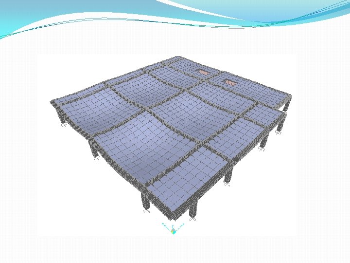
3 D Model
Design Loads �Vertical loads : Dead and Live loads �Lateral loads : Wind and Earthquake loads
Computer programs �In analysis and design: SAP 2000 (v 14. 2. 2) program
Loads combination �The load combinations are: according to ACI 318 -11 9. 2. 1: Wu= 1. 4 D. L Wu= 1. 2 D. L+ 1. 6 L. L Service load = 1. 0 D. L + 1. 0 L. L
2. Loads
Loads �Dead load and superimposed dead load: Dead load: A constant load in a structure that is due to the weight of the members superimposed dead load: is defined as any applied load other than dead load like: Plastering, tiles, paint, …etc
To find S. D. L: Material Plain concrete Reinforced concrete Glass Unit weight k. N/m 3 23. 5 24 25. 5 Mild steel 77 Hardwood 11 Softwood 8
Live Load �Live loads are the weights of people, furniture, supplies, machines, stores, … �In order to find the live loads there two ways: 1 - Codes like IBC’s table 2 - Experience
Wind Load �Building and other structures, including the main Wind - force Resisting System , shall be designed to resist wind load. - Uplift load - Shear load - Lateral Load
Earthquake Loads �Earthquake loads are dynamic loads, which acting on the whole structure, and may occur in any direction.
Structural system for shear resistance � 1. Rigid Structural Frame �Rigid frame structures provide more stability. This type of frame structures resists the shear, moment, and torsion more effectively than any other type of frame structures
Structural system for shear resistance, cont. � 2. Braced Structural Frames �It use to the resistance against the lateral forces and sideways forces due to applied load
Structural system for shear resistance, cont. � 3. Shear walls: shear walls can be used to provide stability of the building frame.
3. Preliminary Design
Preliminary Design �There are many structural systems that may be used this building structure �The following diagram shows slab systems classification based on load path and type of section: Slabs One way On way joist slab On way solid slab Tow way Two way joist slab Flat slab Two way solid slab with beam
Floor Structural system �The structural systems that was chosen for this building, A two way solid slab with dropped beams
Minimum thickness of Slab Simply supported One end continuous Two end continuous Cantilever For beam and ribbed slab L / 16 L / 18. 5 L / 21 L / 8 For solid slab L / 20 L / 24 L / 28 L / 10 Supports
Preliminary Design �Slab thicknesses For two way slab systems, we will specify the minimum slab thickness based on deflection criteria h min= 220 mm
Preliminary Design, cont. �Beams: The depth of internal beams = 60 cm The depth of external beams = 40 cm �Columns : The dimension of columns is to be assumed as 50 × 50 cm
4. Static Design �Final Dimensions element Dimensions/thickness Tow way solid slab 25 cm Main beams 80 cm width x 60 cm depth Other main beams 60 cm width x 40 cm depth All columns 50 cm x 50 cm shear wall 30 cm
�Final static design loads Slab Super imposed dead load Live load Tow way solid slab 4 k. N/m² 5 k. N/m²
Verification of SAP model � 1 -Compatibility:
� 2 -Equilibrium: �- Sap result : �- manual Calculation Load type service Hand results (KN) 13439. 52 Solid SAP results (KN) 13802. 658 Error % 2. 62
� 3. Stress- strain relationship: �This item include verification the values of moment on middle strip, column strip Load M-ve(left) (k. N. m/m) M+ve (k. N. m/m) M-ve(right) (k. N. m/m) Sap Result 303. 69 252. 43 234. 2 521. 4 Hand Result 291. 16 307. 23 291. 16 598. 4 Error 4. 1 17. 8 19. 5 16. 6
�After achieving compatibility, equilibrium and stress strain relationship, we are confident that the model works well and we can start static design.
5. Wind & Earthquake load �By calculating the Wind load and Earthquake load The following results was obtained
Calculation of wind load: �Equation that use in this calculation qz = 0. 613*kz*kzt*kd*v 2*I �where : kz will find by using table 6. 3 in code ASCE kzt can be assume 1 kd with value of 0. 85 I for tower equal 2
Wind Load NO. of floor Accumulative Height kz qz P(N/mm^2) Ground 1 0 4. 77 0. 575 665. 653 452. 644 2 9. 19 0. 7 563. 7636 383. 3592 3 13. 12 0. 78 628. 1937 427. 1717 4 17. 05 0. 83 668. 4625 454. 5545 5 20. 98 0. 89 716. 7851 487. 4139 6 24. 88 0. 93 749. 0002 509. 3201 7 28. 78 0. 97 781. 2153 531. 2264 8 32. 68 1. 01 813. 4303 553. 1326 9 36. 58 1. 04 837. 5916 569. 5623 10 40. 48 1. 06 853. 6992 580. 5154 11 44. 38 1. 1 885. 9142 602. 4217 12 48. 28 1. 13 910. 0755 618. 8514 13 52. 18 1. 15 926. 183 629. 8045 14 56. 08 1. 18 950. 3443 646. 2342 15 59. 98 1. 19 958. 3981 651. 7107 16 63. 88 1. 21 974. 5056 662. 6638 17 67. 78 1. 23 990. 6132 673. 617 18 72. 01 1. 25 1006. 721 684. 5701 19 75. 94 1. 28 1030. 882 700. 9998 20 80. 63 1. 3 1046. 99 711. 9529
Earthquake load: NO. of floor Area ( m^2) Dead load (ton) Accumulative Height (m) W* h Wx Fx (ton) Ft(ton) Vx(ton) 1 596. 8 447. 6 4. 77 2135. 052 8608. 8 62. 9728 54. 78 117. 7528 2 576. 3 432. 225 9. 19 3972. 148 8161. 2 115. 0169 54. 78 232. 7697 3 598. 5 448. 875 13. 12 5889. 24 8176. 575 164. 5119 54. 78 397. 2816 4 600. 5 450. 375 17. 05 7678. 894 8159. 925 213. 3549 54. 78 610. 6365 5 600. 5 450. 375 20. 98 9448. 868 8158. 425 262. 4846 54. 78 873. 1211 6 600. 5 450. 375 24. 88 11205. 33 8158. 425 311. 2783 54. 78 1184. 399 7 600. 5 450. 375 28. 78 12961. 79 8158. 425 360. 0719 54. 78 1544. 471 8 600. 5 450. 375 32. 68 14718. 26 8158. 425 408. 8655 54. 78 1953. 337 9 600. 5 450. 375 36. 58 16474. 72 8158. 425 457. 6591 54. 78 2410. 996 10 600. 5 450. 375 40. 48 18231. 18 8158. 425 506. 4527 54. 78 2917. 449 11 600. 5 450. 375 44. 38 19987. 64 8158. 425 555. 2463 54. 78 3472. 695 12 600. 5 450. 375 48. 28 21744. 11 8158. 425 604. 04 54. 78 4076. 735 13 600. 5 450. 375 52. 18 23500. 57 8158. 425 652. 8336 54. 78 4729. 568 14 600. 5 450. 375 56. 08 25257. 03 8158. 425 701. 6272 54. 78 5431. 196 15 600. 5 450. 375 59. 98 27013. 49 8158. 425 750. 4208 54. 78 6181. 617 16 600. 5 450. 375 63. 88 28769. 96 8158. 425 799. 2144 54. 78 6980. 831 17 600. 5 450. 375 67. 78 30526. 42 8158. 425 848. 008 54. 78 7828. 839 18 519. 9 389. 925 72. 01 28078. 5 8158. 425 900. 9304 54. 78 8729. 769 19 427. 9 320. 925 75. 94 24371. 04 8218. 875 957. 1391 54. 78 9686. 908 20 352 264 80. 63 21286. 32 8287. 875 1024. 783 54. 78 10711. 69
6. Slab and Beam
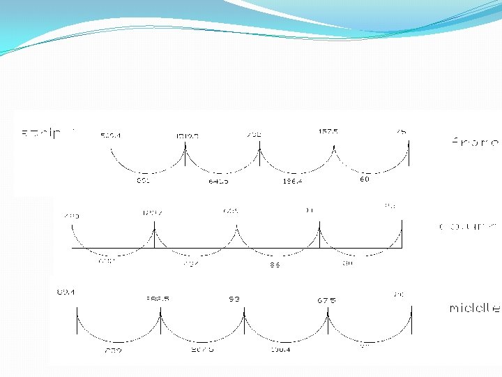
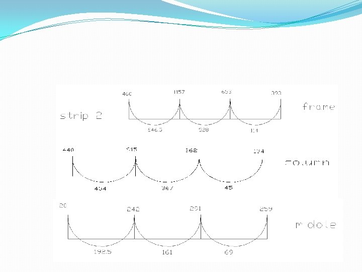
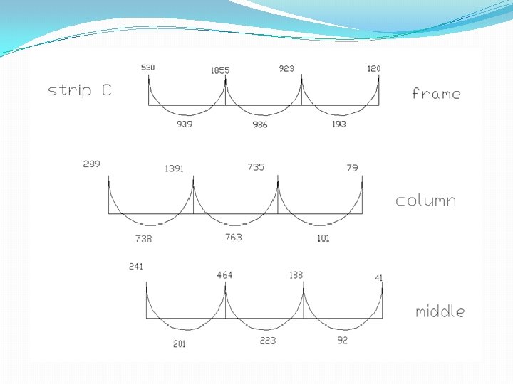
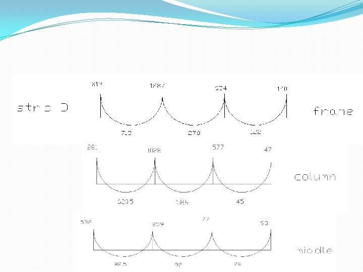
�For Slab: Because the type of slab is two way in the project, more than one strip is taken in each direction as frame and the value of moment in each frame shown as follow:
Frame 2 :
Frame C :
Frame D :
Layout of beams
�For Beams: Beams are the structural elements that transmit the tributary loads from floor slabs to vertical supporting columns. Beam 3 moment
Design of Beams: Name beam 1 beam 2 beam 3 beam 4 beam 5 beam 6 beam 7 beam 8 beam 9 beam 10 beam 11 beam 12 Mu (Kn. m) 64. 5 99 387 639 548 897. 6 400 711. 4 66 116 54 81 61 115 54 73 132 63. 9 490 916 618 555 186 345 b (mm) 600 800 800 800 600 600 800 800 800 600 d (mm) 400 600 600 600 400 400 600 600 600 400 steel ratio 0. 00178 0. 00276 0. 00362 0. 00613 0. 00521 0. 00883 0. 00375 0. 00687 0. 00182 0. 00325 0. 00149 0. 00225 0. 00168 0. 00322 0. 00149 0. 00202 0. 00121 0. 00058 0. 00463 0. 00903 0. 00591 0. 00528 0. 00531 0. 01033 As (mm^2) 792 1739. 75 2940. 48 2500. 06 4238. 77 1800. 29 3296. 76 792 792 1584 2223. 46 4334. 00 2838. 13 2533. 66 1274. 04 2479. 92 moment sign positive negative positive negative positive negative
analysis of beams for shear: The value of Vu for each beam are taken from SAPas follow: For external beam, ф. Vc =127 k. N For internal beam , ф. Vc = 317 KN Beam 1: Vu =54. 2 KN ф. Vc =127 k. N No need for shear reinforcement Beam 2: Vu =390 KN ф. Vc = 317 Kn Need for shear reinforcement Beam 3: Vu =546 KN ф. Vc = 317 Kn Need for shear reinforcement
Beam 4: Vu =421 KN ф. Vc = 317 Kn Need for shear reinforcement Beam 5: Vu =85 KN ф. Vc = 127 Kn Need minimum shear reinforcement Beam 6: Vu =96 KN ф. Vc = 127 Kn Need minimum shear reinforcement
Beam 7: Vu = 111 KN ф. Vc = 127 Kn Need minimum shear reinforcement Beam 8: Vu =269 KN ф. Vc = 317 Kn Need minimum shear reinforcement Beam 9: Vu =81. 3 KN ф. Vc = 127 Kn Need minimum shear reinforcement
Beam 10: Vu =466. 8 KN ф. Vc = 317 Kn Need for shear reinforcement Beam 11: Vu =571 KN ф. Vc = 317 Kn Need for shear reinforcement Beam 12: Vu =175 KN ф. Vc = 127 Kn Need for shear reinforcement
7. Footing �Layout of columns
loads on columns and shear wall Column number area load total load on column no. of shear wall area load 1 17 204. 68 4912. 32 1 10. 4 125. 216 2 7. 5 90. 3 2167. 2 2 15. 7 189. 028 3 1 12. 04 288. 96 3 30. 15 363. 006 4 32. 8 394. 912 9477. 888 4 32. 3 388. 892 5 47 565. 88 13581. 12 5 22. 3 268. 492 6 25. 4 305. 816 7339. 584 6 34. 4 414. 176 7 2 24. 08 577. 92 7 34. 3 412. 972 8 8. 5 102. 34 2456. 16 8 12. 4 149. 296 9 5. 5 66. 22 1589. 28 9 7. 3 87. 892 10 14 168. 56 4045. 44 10 5. 8 69. 832 11 5. 2 62. 608 1502. 592 11 10. 1 121. 604 12 20. 3 244. 412 5865. 888 12 8 96. 32 13 20. 1 242. 004 5808. 096 13 4. 7 56. 588 14 8. 7 104. 748 2513. 952 14 5. 3 63. 812 15 44. 8 539. 392 12945. 408 15 5 60. 2 16 5. 7 68. 628 1647. 072 16 3. 7 44. 548 17 6. 9 83. 076 1993. 824 17 8. 1 97. 524 18 64. 5 776. 58 18637. 92 18 4. 9 58. 996 19 66. 3 798. 252 19158. 048 19 1. 4 16. 856 20 5. 7 68. 628 1647. 072 20 6. 64 79. 9456 21 16. 1 193. 844 4652. 256 22 14. 8 178. 192 4276. 608 23 4. 8 57. 792 1387. 008
Footing Analysis: �The total area of footing = 285. 55+217. 76= 503. 31 m 2 �The area of the first floor is 594. 6 m 2 �Total area of footing = 72. 64% > 65% so mat foundation is the most suitable for this case.
�The most Critical column was chosen is the column that carries the largest load, Pu = 19158 KN �Practical thickness of mat foundation is calculated by using this equation �hmin = 15*sqrt(pu) = 15*sqrt(19158 ) = 2076 mm used h = 2. 1 m
In project 2 , we will study the following: • Design of 3 D static • Design of 3 D dynamic • Design of mat foundation • Design of stairs • Design of columns and shear walls • Design of swimming pool