AnNajah National University Faculty of Engineering Civil Engineering


 üASCE 7")


 equal to L/33")

: We chose the critical beam span")


 - Shopping and restaurants")


- Slides: 38
An-Najah National University ﺟﺎﻣﻌﺔ ﺍﻟﻨﺠﺎﺡ ﺍﻟﻮﻃﻨﻴﺔ Faculty of Engineering ﻛﻠﻴﺔ ﺍﻟﻬﻨﺪﺳﺔ Civil Engineering Department Graduation Project Analysis and Design of Al-Assi Mall Supervisor: Dr. Shaker Bitar. Prepared by: Hala Bouzia Mohammed Bayyari Muzna Masri
Outline 1. Introduction. 2. Preliminary design. 3. Three Dimensional structural analysis. 4. ETABS model checks.
Introduction Project description : üA commercial building located in Nablus , Palestine. üconsist of ten floors with total area of 11313. 82 m². üThe building will be assessed as a parking facility at the heart of the commercial center in Nablus.
Architectural plan for Base Floor
Architectural plan for Ground Floor
Architectural plan for First Floor
Architectural plan for Second to Seventh Floor
Architectural plan for Eighth Floor
• Codes and Standards: üACI 318 -14 (American concrete institute ) üASCE 7 -16 (American Society Of Civil Engineers ) üAASHTO (American Association of State Highway and Transportation ) • Materials : 1. Structural : ü Reinforcement steel ü Concrete 2. Non Structural Material Density KN/m 3 Fill 16 Mortar 23 Plaster 23 Tile 25
• Gravity loads : ü Live Load : Parking (2. 0 k. N/m 2) Shopping and restaurants (5. 0 k. N/m 2) Stair(5. 0 k. N/m 2) ü Super Impose Dead Load: Parking(1. 0 k. N/m 2) Shopping , restaurants & Stair (2. 5 k. N/m 2) üSlab Own Weight (8. 75 k. N/m 2)
Geometry design of Parking Garage In our project we found that the parking doesn’t satisfy AASHTO specifications of : 1) Ramp slope 2) Ramp width 3) Turning circles Some of criteria we used: Ramp width ramp width = 7. 0 m Ramp slope In AASHTO the maximum allowable slope is about 16% Ramp Slope% From ground 15. 9 & 10 From first (& all other ramps the same) 15
Plan before modification Plan after modification
section for building before modification
First ramp after modified second ramp after modification Computer programs: ETAPS 2016 is used to analyze and design the structural elements (3 D). sp. Slab is used to analysis and design the slabs on the project.
Equivalent frame method The slab is divided into series of two-dimensional frames in each direction, positive and negative moments are computed by an elastic frame analysis. Then, these moments are divided between middle and column strips.
To ensure if sp. SLAB software analyzed correctly we applied example 13. 3 (DESIGNE OF CONCRETE STRUCTURES 14 th edition in SI UNITS)
Preliminary design. Ø Slab System Two-way solid slab and flat plate The ratio of the long span to the short span (L/B) =1. 39 which is less than 2 so it’s preferable to design the slab as two way solid slab 11 m 7. 9 m
Preliminary design. Slab thickness In our structure the minimum thickness (t) equal to L/33 t=11/33=0. 33 m So we used t=350 mm
Preliminary design. Check slab for Punching Slab thickness t=350 mm , d=310 mm �� �������� = �� ������ Л(�� ^4)/64=1/12∗ �� ∗ ℎ b =h= 1. 051 mm Tributary area=(7. 4/2)+(11/2)∗ 7. 9 = 72. 68�� ���� = (0. 35 ∗ 25 + 1) ∗ 1. 2 + (2 ∗ 1. 6) = 14. 9 KN/m^2 ���� = (72. 68∗ 14. 9)-14. 9(1. 05+0. 31)^2= 1055. 3���� =1055. 3/0. 75=1407. 06���� �� 0 = (1051 + 310)∗ 4=5444���� , �� =310���� , �� =40, �� =1 ������ 1=[0. 17(1+1/2)∗(28^0. 5)∗ 5444∗ 310]/1000=2277. 18������ 2=[0. 083∗({40∗ 310/5444}+2)∗(28^0. 5)∗ 5444∗ 310]/1000=3170. 66������ 3=[0. 33∗(28^0. 5)∗ 5444∗ 310]/1000=2976. 71���� Minimum ������ =2277. 18���� > ���� =1407. 06���� …… OK
Preliminary design. Ø Beam dimensions Beam thickness (h): We chose the critical beam span length which is 11 m h=11/21=0. 52 m We used h=550 mm Beam width: Minimum allowable width=200 mm …. Try 300 mm
Preliminary design. Ø Columns The slenderness for columns is calculated as shown below: Assume Sway ……. . KL/R <22 K=1, L= 5. 1, r = 0. 25 D, D=1. 2 m KL/R=17 < 22 ……so we have short column Columns dimensions: 12666. 104*10^3=0. 75*0. 85[0. 85*28(Ag-0. 02 Ag)+420*0. 02 Ag] Ag=6262814. 05 mm…. . so Dmin=892. 9 mm So we take in this part of project diameter as it come from architectural drawing=1200 mm
Three Dimensional structural analysis
ØInput data of the Models. Material: f′�� = 28 MPa for columns & shear walls. f′�� = 24 MPa for beams & reinforced slabs. The modifiers of Columns, Beams, Slab and Shear wall are shown in table: But, Torsion modifiers are too small ������ = ��. ������ No need for torsional reinforcement. Section Modifiers Column 0. 7 Beam 0. 35 Slab 0. 35 Shear wall 0. 7
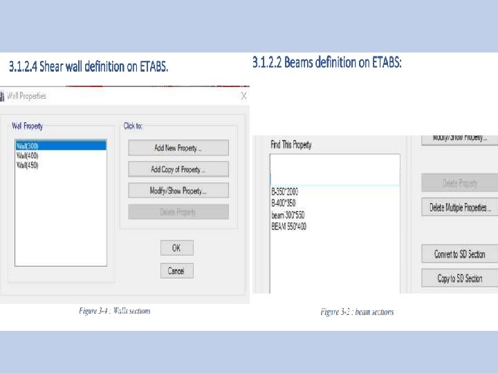
ØSections on ETABS:
Ø Loads on ETABS: üLoad Cases: Live load: -Parking ………… (2. 0 k. N/m 2) - Shopping and restaurants ………… (5. 0 k. N/m 2) - Stair………… (5. 0 k. N/m 2)
Superimposed dead load: -Parking ………… (1. 0 k. N/m 2) - Shopping and restaurants ………… (2. 5 k. N/m 2) - Stair………… (2. 5 k. N/m 2)
ETABS model checks ØDrawing structural model ØCompatibility ØExternal equilibrium ØStress Strain Check ØSlab deflection
Ø Drawing structural model
Ø Compatibility As shown in period = 0. 938 which is Acceptable
Ø External equilibrium 1. Hand calculation Dead loads = 143900. 1644 k. N Live loads = 32944. 64869 Kn 2. Etabs values:
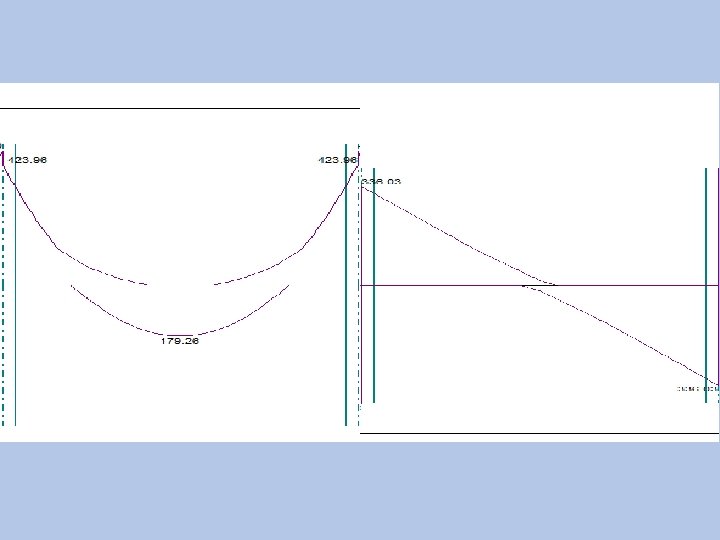
Ø Stress Strain Check. For interior span in EF frame in X-direction: E F
For moment values from sp. SLAB :
Ø Slab deflection
max ���������� = 7. 9 ∗ 1000 /240 = 32. 917 mm 32. 687 < 32. 917 mm 8. 596 < 32. 917 mm
CONCLUSION As a result of this stage of project: 1. we modified this building and make a proper design for its parking garage. 2. make preliminary design for building. 3. prepare this building for second stage. In the stage #2 of this project we will: 1. Design this building to gravity and seismic loads. 2. design the most suitable footing for this building.