Analisis Sistem Kendali Industri Cycloconverters Introduction Cycloconverters directly

 to ac")

 A positive center-tap thyristor converter is connected in anti-parallel with a")
")
 An integral half-cycle output wave is created which has a fundamental")
 3 to single phase conversion can be achieved using either of")
 A Thevenin equivalent circuit for the dual converter is shown below:")
 The input and output voltages are adjusted to be equal and")
 Voltage-tracking between the input and output voltages is achieved by setting")
 A 3 to 3 cycloconverter can be implemented using 18 thyristors")
 Each phase group functions as a dual converter but the firing")
 An output phase wave is achieved by sinusoidal modulation of the")
 A variable voltage, variable frequency motor drive signal can be achieved")
 A 3 to 3 bridge cycloconverter (widely used in multi-MW applications)")
 The output phase voltage v 0 can be written as: where")
 From these equations, we can write: and Thus for zero output")
 The phase group of a cycloconverter can be operated in two")
 The equivalent circuit of a phase group with an IGR is")
")
 At t=0, +ve load current is taken by the +ve converter")
 The +ve and -ve converter currents can be expressed as: The")
")
 ¡ ¡ ¡ Advantages of circulating current mode of operation, over")
 In the blocking mode of operation, no IGR is used and")
 Since the cycloconverter is usually connected directly to a motor, the")
 A major disadvantage of cycloconverters is poor DPF (displacement power factor).")
 Assume the +ve converter is operating in continuous conduction and is")
 The Fourier series of the line current is given by: where")
 Since the supply’s active and reactive power components are contributed only")
 These equations can be rewritten as: If the firing angle is")
")
 The expression for the average reactive powe contributed by the line,")
 P 0 and Q 0 are given by: and Since the")
 DPF = = = where tan = Q 0/Pi (=Q 0/P")
 This equation for DPF applies when additional phase groups are added")
 See Bose text pp. 180 -184 for methods to improve DPF.")
 The control of a cycloconverter is very complex. A typical variable")
 Generator bus with regulated voltage but variable frequency (1333 -2666 Hz)")
 3 sinusoidal control signals are generated through the vector rotator. The")
 Details of modulator are shown below:")
.")
 A matrix of nine switches where any input phase can be")
")
 Matrix converters offer the advantage over thyristor cycloconverters of being able")

- Slides: 62
Analisis Sistem Kendali Industri Cycloconverters
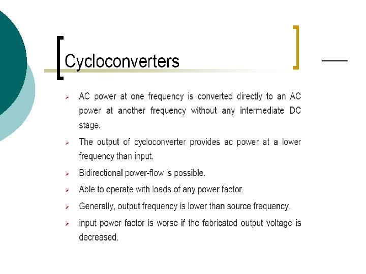
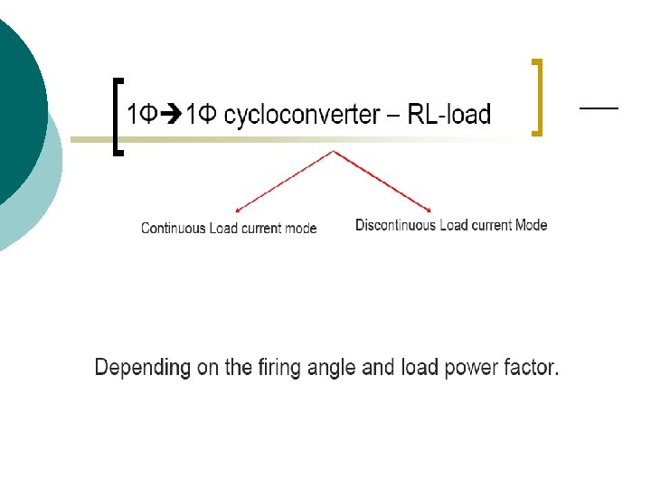
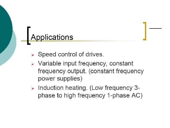
Introduction Cycloconverters directly convert ac signals of one frequency (usually line frequency) to ac signals of variable frequency. These variable frequency ac signals can then be used to directly control the speed of ac motors. Thyristor-based cycloconverters are typically used in low speed, high power (multi-MW) applications for driving induction and wound field synchronous motors.
Phase-Controlled Cycloconverters The basic principle of cycloconversion is illustrated by the single phase-to-single phase converter shown below.
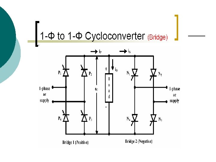
Phase-Controlled Cycloconverters (cont’d) A positive center-tap thyristor converter is connected in anti-parallel with a negative converter of the same type. This allows current/voltage of either polarity to be controlled in the load. The waveforms are shown on the next slide.
Phase-Controlled Cycloconverters (cont’d)
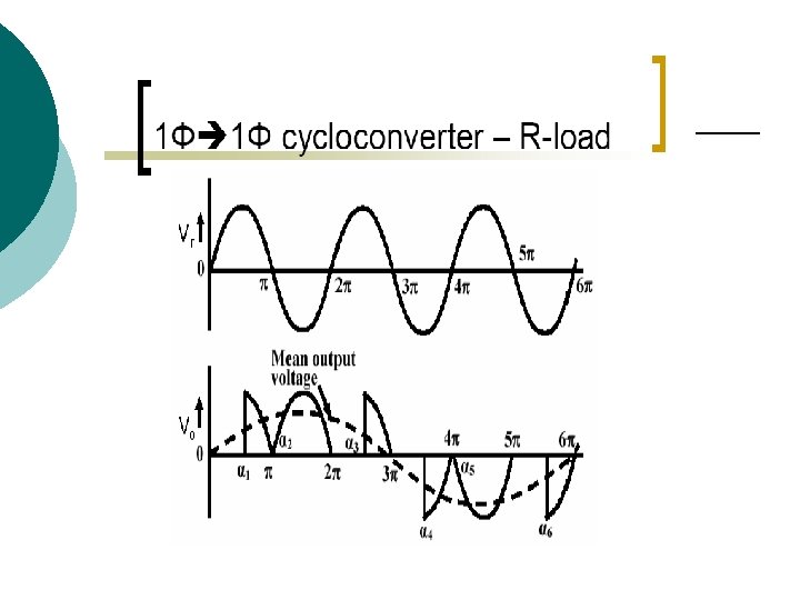
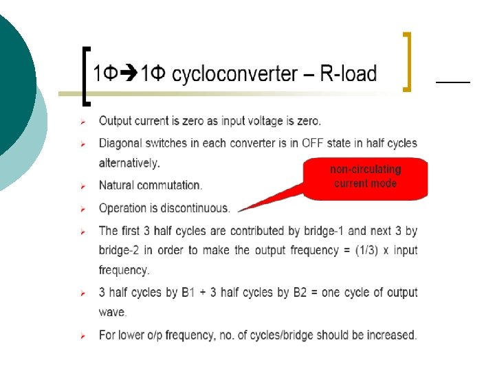
Phase-Controlled Cycloconverters (cont’d) An integral half-cycle output wave is created which has a fundamental frequency f 0=(1/n) fi where n is the number of input half-cycles per half-cycle of the output. The thyristor firing angle can be set to control the fundamental component of the output signal. Step-up frequency conversion can be achieved by alternately switching high frequency switching devices (e. g. IGBTs, instead of thyristors) between positive and negative limits at high frequency to generate carrier-frequency modulated output.
Phase-Controlled Cycloconverters (cont’d) 3 to single phase conversion can be achieved using either of the dual converter circuit topologies shown below:
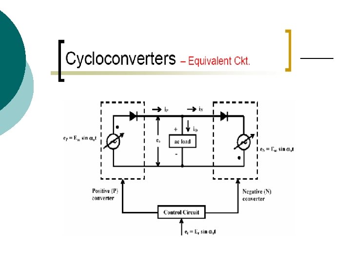
Phase-Controlled Cycloconverters (cont’d) A Thevenin equivalent circuit for the dual converter is shown below:
Phase-Controlled Cycloconverters (cont’d) The input and output voltages are adjusted to be equal and the load current can flow in either direction. Thus, where Vd 0 is the dc output voltage of each converter at zero firing angle and p and N are the input and output firing angles. For a 3 halfwave converter Vd 0 =0. 675 VL and Vd 0 = 1. 35 VL for the bridge converter (VL is the rms line voltage).
Phase-Controlled Cycloconverters (cont’d) Voltage-tracking between the input and output voltages is achieved by setting the sum of the firing angles to . Positive or negative voltage polarity can be achieved as shown below:
Phase-Controlled Cycloconverters (cont’d) A 3 to 3 cycloconverter can be implemented using 18 thyristors as shown below:
Phase-Controlled Cycloconverters (cont’d) Each phase group functions as a dual converter but the firing angle of each group is modulated sinusoidally with 2 /3 phase angle shift -> 3 balanced voltage at the motor terminal. An inter-group reactor (IGR) is connected to each phase to restrict circulating current.
Phase-Controlled Cycloconverters (cont’d) An output phase wave is achieved by sinusoidal modulation of the thyristor firing angles.
Phase-Controlled Cycloconverters (cont’d) A variable voltage, variable frequency motor drive signal can be achieved by adjusting the modulation depth and output frequency of the converter. The synthesized output voltage wave contains complex harmonics which can be adequately filtered out by the machine’s leakage inductance.
Phase-Controlled Cycloconverters (cont’d) A 3 to 3 bridge cycloconverter (widely used in multi-MW applications) can be implemented using 36 thyristors as shown below:
Phase-Controlled Cycloconverters (cont’d) The output phase voltage v 0 can be written as: where V 0 is the rms output voltage and 0 is the output angular frequency. We can also write: where the modulation factor, mf is given by:
Phase-Controlled Cycloconverters (cont’d) From these equations, we can write: and Thus for zero output voltage, mf=0 and P= N= /2. For max. phase voltage, mf=1 => P=0, N= . See below figure for P and N values for mf=0. 5 and 1.
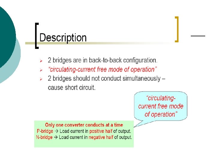
Phase-Controlled Cycloconverters (cont’d) The phase group of a cycloconverter can be operated in two modes: 1) Circulating current mode 2) Non-circulating current (blocking) mode In the circulating current mode, the current continuously circulates between the +ve and -ve converters. Although the fundamental output voltage waves of the individual converters are equal, the harmonics will cause potential difference which will result in short-circuits without an IGR.
Phase-Controlled Cycloconverters (cont’d) The equivalent circuit of a phase group with an IGR is shown below. The inclusion of an IGR leads to self-induced circulating current as illustrated in the next slide.
Phase-Controlled Cycloconverters (cont’d)
Phase-Controlled Cycloconverters (cont’d) At t=0, +ve load current is taken by the +ve converter only (i. P=i 0). From 0 -> /2, rising +ve load current will create a +ve voltage drop (v. L=Ldi 0/dt) in the primary winding of the IGR. This creates a -ve voltage drop in the secondary winding of the IGR -> DN reverse biased. no current flow in the -ve converter. At /2, i 0 peaks at Im-> v. L=0. After this v. L tends to reverse polarity inducing current in the -ve converter. Voltage across IGR becomes clamped to 0 -> self-induced circulation current between +ve and -ve converters.
Phase-Controlled Cycloconverters (cont’d) The +ve and -ve converter currents can be expressed as: The self-induced circulating current is simply i. P-i. N. In practice, the waves will not be pure sine waves but include a ripple current. Practical waveforms are shown on the next slide.
Phase-Controlled Cycloconverters (cont’d)
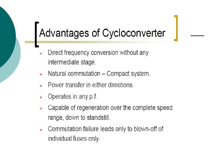
Phase-Controlled Cycloconverters (cont’d) ¡ ¡ ¡ Advantages of circulating current mode of operation, over blocking mode include: Output phase voltage wave has lower harmonic content than in blocking mode. Output frequency range is higher. Control is simple. Disadvantages Bulky IGR increases cost and losses. Circulating current increases losses in thyristors. Over-design increases cost.
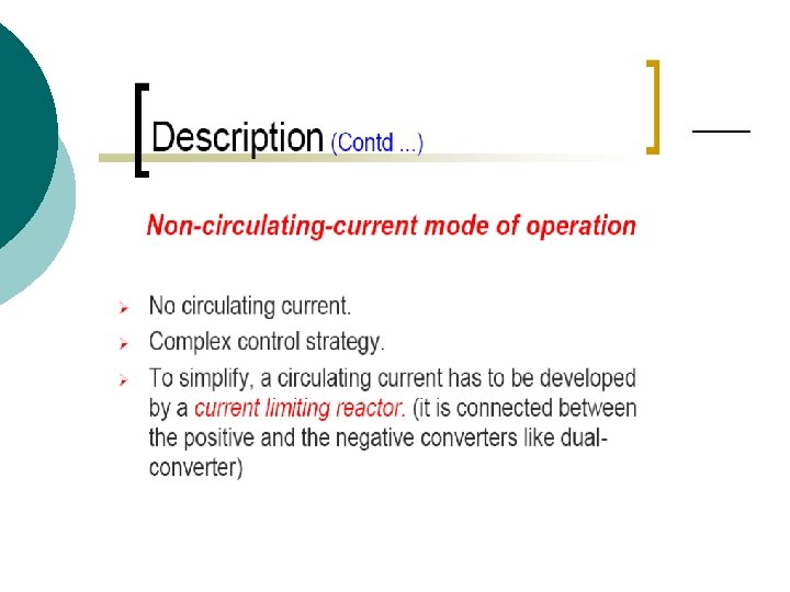
Phase-Controlled Cycloconverters (cont’d) In the blocking mode of operation, no IGR is used and only one converter is conducting at any time. Zero current crossing detection can be used to select +ve or -ve converter conduction as shown below:
Phase-Controlled Cycloconverters (cont’d) Since the cycloconverter is usually connected directly to a motor, the harmonics from the converter will induce torque pulsations and machine heating resulting in increased machine losses. Also, since the cycloconverter is essentially a matrix of switches without energy storage (neglecting IGR) Pin=Pout. Thus distortions in the output voltage waveform reflect back into the line input. See text for a discussion of the load voltage and line harmonics.
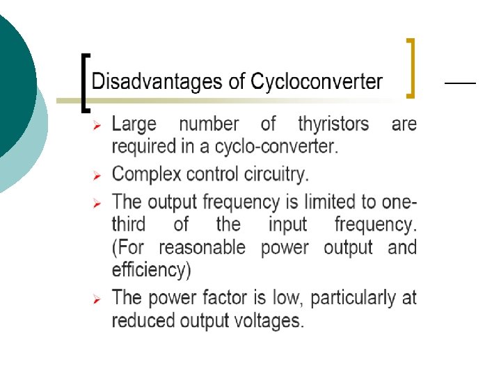
Phase-Controlled Cycloconverters (cont’d) A major disadvantage of cycloconverters is poor DPF (displacement power factor). To calculate DPF, consider a phase group of an 18 -thyristor cycloconverter shown below.
Phase-Controlled Cycloconverters (cont’d) Assume the +ve converter is operating in continuous conduction and is connected to a high inductance load and assume that the cycloconverter is operating at low frequency. Segments of the output current and voltage waves are as shown below:
Phase-Controlled Cycloconverters (cont’d) The Fourier series of the line current is given by: where i 0 is the load current and is the supply frequency. The current wave has a dc component and a fundamental component with a lagging phase angle, P.
Phase-Controlled Cycloconverters (cont’d) Since the supply’s active and reactive power components are contributed only by the fundamental current, the instantaneous active Pi’ and reactive power Qi’ for the positive converter is given by: where Vs =rms line voltage.
Phase-Controlled Cycloconverters (cont’d) These equations can be rewritten as: If the firing angle is constant, the converter acts as a rectifier and Vd=Vd 0 cos P and i 0=Id. In a cycloconverter P and i 0 vary sinusoidally and so Pi’ and Qi’ are also modulated. We need to average these parameters to determine loading on the source.
Phase-Controlled Cycloconverters (cont’d)
Phase-Controlled Cycloconverters (cont’d) The expression for the average reactive powe contributed by the line, Qi, is given by: where = load power factor angle. Performing the integration above yields: where P 0, Q 0 are the real and reactive output power phase, respectively.
Phase-Controlled Cycloconverters (cont’d) P 0 and Q 0 are given by: and Since the real output power = real input power, we can write: The input DPF can be expressed as: DPF = cos i =
Phase-Controlled Cycloconverters (cont’d) DPF = = = where tan = Q 0/Pi (=Q 0/P 0)
Phase-Controlled Cycloconverters (cont’d) This equation for DPF applies when additional phase groups are added or if a 36 -thyristor implementation is considered. mf=1 was assumed in this derivation. For mf 1: The maximum value of line DPF is 0. 843.
Phase-Controlled Cycloconverters (cont’d) See Bose text pp. 180 -184 for methods to improve DPF.
Phase-Controlled Cycloconverters (cont’d) The control of a cycloconverter is very complex. A typical variable speed constant frequency (VCSF) system is shown below:
Phase-Controlled Cycloconverters (cont’d) Generator bus with regulated voltage but variable frequency (1333 -2666 Hz) is fed to the cycloconverter phase groups. (A generator speed variation of 2: 1 is assumed). The dual converter in each phase group uses a low-pass filter to generate a sinusoidal signal. modulator receives biased cosine waves from generator bus voltage and sinusoidal control signal voltages to generate thyristor firing angles.
Phase-Controlled Cycloconverters (cont’d) 3 sinusoidal control signals are generated through the vector rotator. The feedback voltage Vs is generated from the output phase voltages.
Phase-Controlled Cycloconverters (cont’d) Details of modulator are shown below:
Matrix Converters These types of cycloconverters use highfrequency, self-controlled ac switches (e. g. IGBTs). A 3 to 3 converter is shown below:
Matrix Converters (cont’d) A matrix of nine switches where any input phase can be connected to any output phase. The switches are controlled by PWM to fabricate an output fundamental voltage whose amplitude and frequency can be varied to control an ac motor. The output waveform synthesis is shown on the next slide.
Matrix Converters (cont’d)
Matrix Converters (cont’d) Matrix converters offer the advantage over thyristor cycloconverters of being able to produce unity PF line current. However, compared to PWM voltagefed converters, the parts count is significantly higher.
High-Frequency Cycloconverters See Bose text pp. 186 -189