Vocoders 1 The Channel Vocoder analyzer n The
- Slides: 23
Vocoders 1
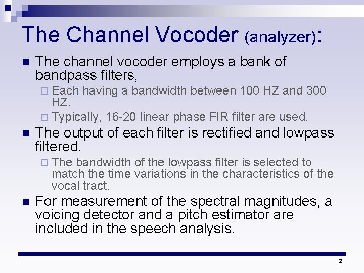
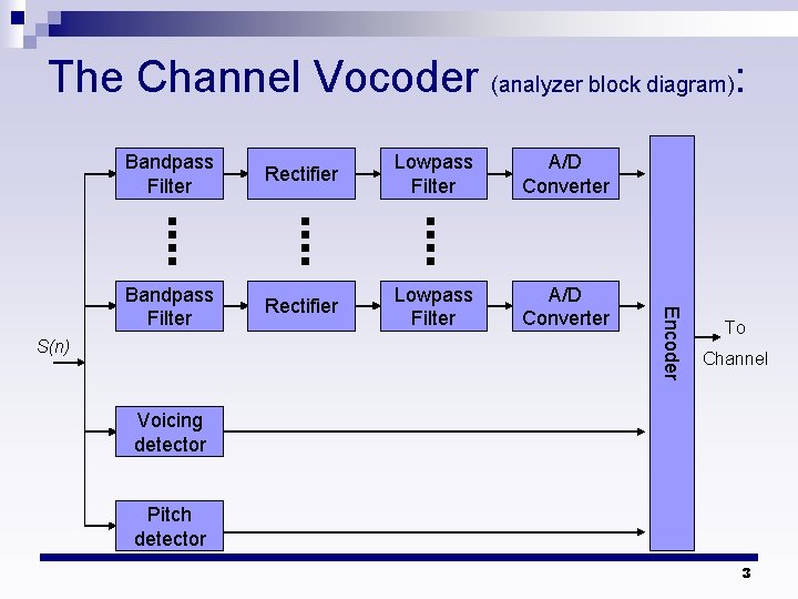
The Channel Vocoder (analyzer): n The channel vocoder employs a bank of bandpass filters, ¨ Each having a bandwidth between 100 HZ and 300 HZ. ¨ Typically, 16 -20 linear phase FIR filter are used. n The output of each filter is rectified and lowpass filtered. ¨ The bandwidth of the lowpass filter is selected to match the time variations in the characteristics of the vocal tract. n For measurement of the spectral magnitudes, a voicing detector and a pitch estimator are included in the speech analysis. 2
The Channel Vocoder (analyzer block diagram): Rectifier Lowpass Filter A/D Converter Bandpass Filter Rectifier Lowpass Filter A/D Converter S(n) Encoder Bandpass Filter To Channel Voicing detector Pitch detector 3
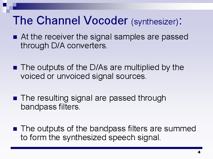
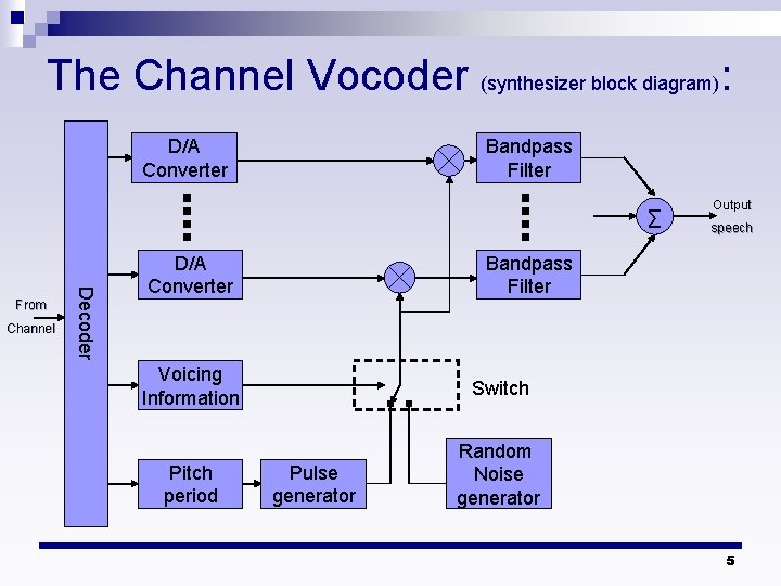
The Channel Vocoder (synthesizer): n At the receiver the signal samples are passed through D/A converters. n The outputs of the D/As are multiplied by the voiced or unvoiced signal sources. n The resulting signal are passed through bandpass filters. n The outputs of the bandpass filters are summed to form the synthesized speech signal. 4
The Channel Vocoder (synthesizer block diagram): D/A Converter Bandpass Filter ∑ Channel Decoder From D/A Converter Output speech Bandpass Filter Voicing Information Switch Pitch period Random Noise generator Pulse generator 5
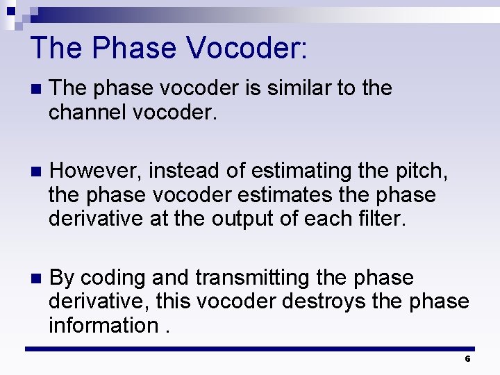
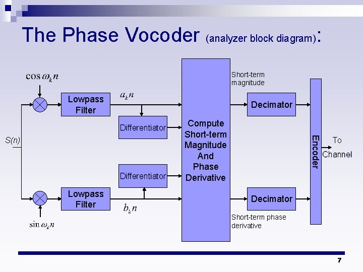
The Phase Vocoder: n The phase vocoder is similar to the channel vocoder. n However, instead of estimating the pitch, the phase vocoder estimates the phase derivative at the output of each filter. n By coding and transmitting the phase derivative, this vocoder destroys the phase information. 6
The Phase Vocoder (analyzer block diagram): Short-term magnitude Lowpass Filter Decimator Differentiator Lowpass Filter Encoder S(n) Compute Short-term Magnitude And Phase Derivative To Channel Decimator Short-term phase derivative 7
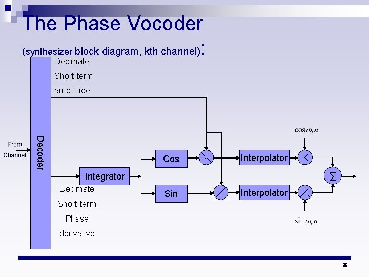
The Phase Vocoder (synthesizer block diagram, kth channel): Decimate Short-term amplitude Channel Decoder From Cos Interpolator ∑ Integrator Decimate Sin Interpolator Short-term Phase derivative 8
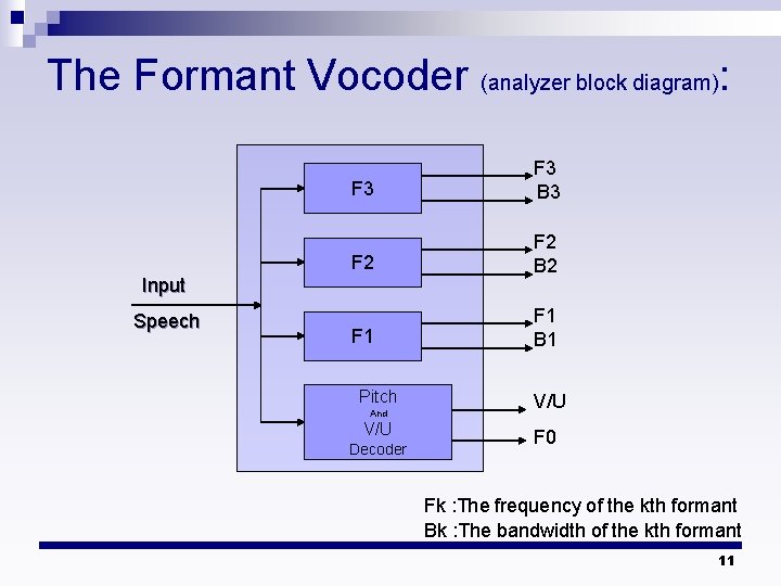
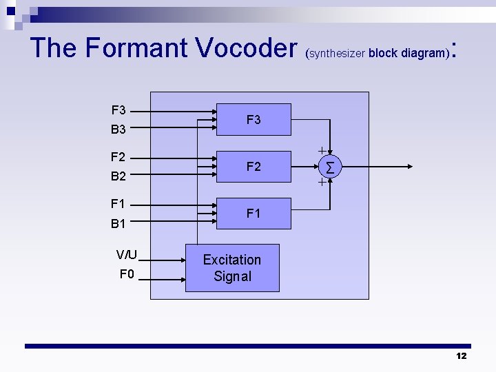
The Formant Vocoder: n The formant vocoder can be viewed as a type of channel vocoder that estimate the first three or four formants in a segment of speech. n It is this information plus the pitch period that is encoded and transmitted to the receiver. 9
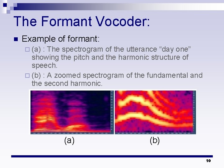
The Formant Vocoder: n Example of formant: ¨ (a) : The spectrogram of the utterance “day one” showing the pitch and the harmonic structure of speech. ¨ (b) : A zoomed spectrogram of the fundamental and the second harmonic. (a) (b) 10
The Formant Vocoder (analyzer block diagram): F 3 B 3 F 2 B 2 F 1 B 1 Input Speech Pitch And V/U Decoder V/U F 0 Fk : The frequency of the kth formant Bk : The bandwidth of the kth formant 11
The Formant Vocoder ( F 3 B 3 F 2 B 2 F 1 B 1 V/U F 0 synthesizer block diagram) : F 3 F 2 ∑ F 1 Excitation Signal 12
Linear Predictive Coding: n The objective of LP analysis is to estimate parameters of an all-pole model of the vocal tract. n Several methods have been devised for generating the excitation sequence for speech synthesizes. n LPC-type of speech analysis and synthesis are differ primarily in the type of excitation signal that is generated for speech synthesis. 13
LPC 10: n This methods is called LPC-10 because of 10 coefficient are typically employed. n LPC-10 partitions the speech into the 180 sample frame. n Pitch and voicing decision are determined by using the AMDF and zero crossing measures. 14
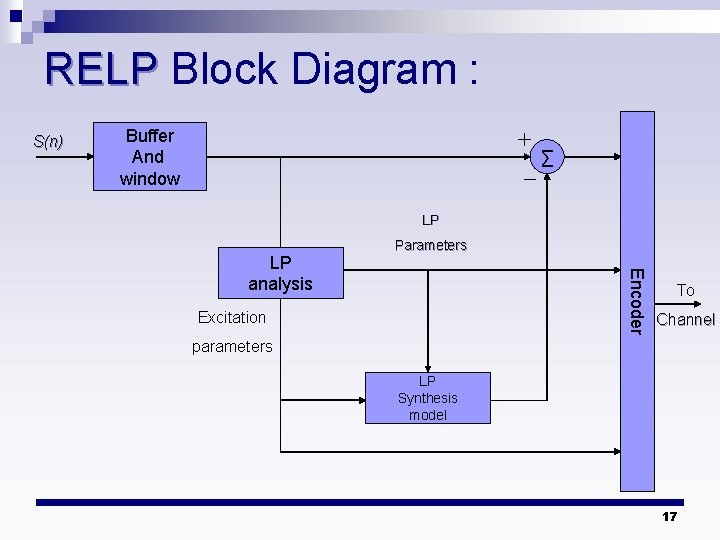
Residual Excited LP Vocoder: n Speech quality in speech quality can be improved at the expense of a higher bit rate by computing and transmitting a residual error, as done in the case of DPCM. n One method is that the LPC model and excitation parameters are estimated from a frame of speech. 15
Residual Excited LP Vocoder: n The speech is synthesized at the transmitter and subtracted from the original speech signal to form the residual error. n The residual error is quantized, coded, and transmitted to the receiver n At the receiver the signal is synthesized by adding the residual error to the signal generated from the model. 16
RELP Block Diagram : S(n) Buffer And window ∑ LP Encoder LP analysis Parameters Excitation To Channel parameters LP Synthesis model 17
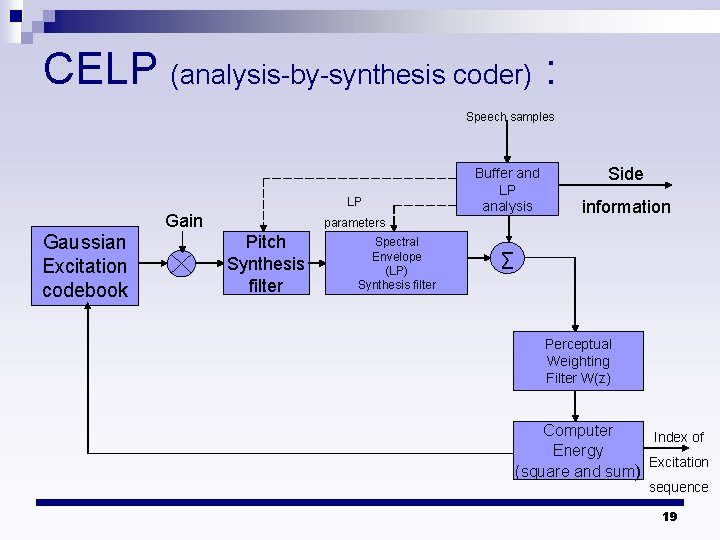
Code Excited LP: n CELP is an analysis-by-synthesis method in which the excitation sequence is selected from a codebook of zero-mean Gaussian sequence. n The bit rate of the CELP is 4800 bps. 18
CELP (analysis-by-synthesis coder) : Speech samples LP Gaussian Excitation codebook Gain Buffer and LP analysis parameters Pitch Synthesis filter Spectral Envelope (LP) Synthesis filter Side information ∑ Perceptual Weighting Filter W(z) Computer Index of Energy Excitation (square and sum) sequence 19
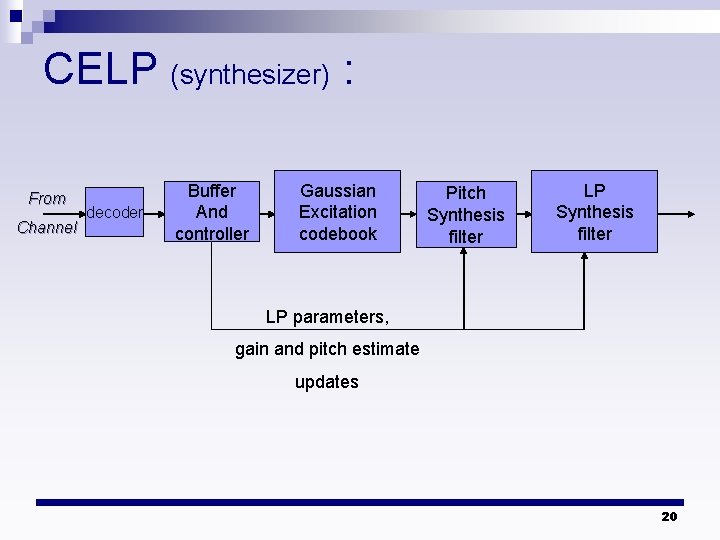
CELP (synthesizer) : From Channel decoder Buffer And controller Gaussian Excitation codebook Pitch Synthesis filter LP parameters, gain and pitch estimate updates 20
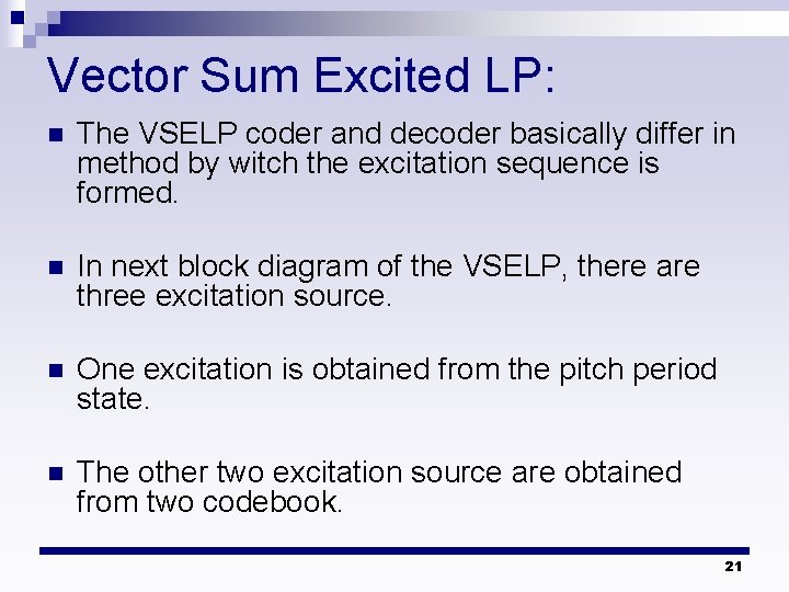
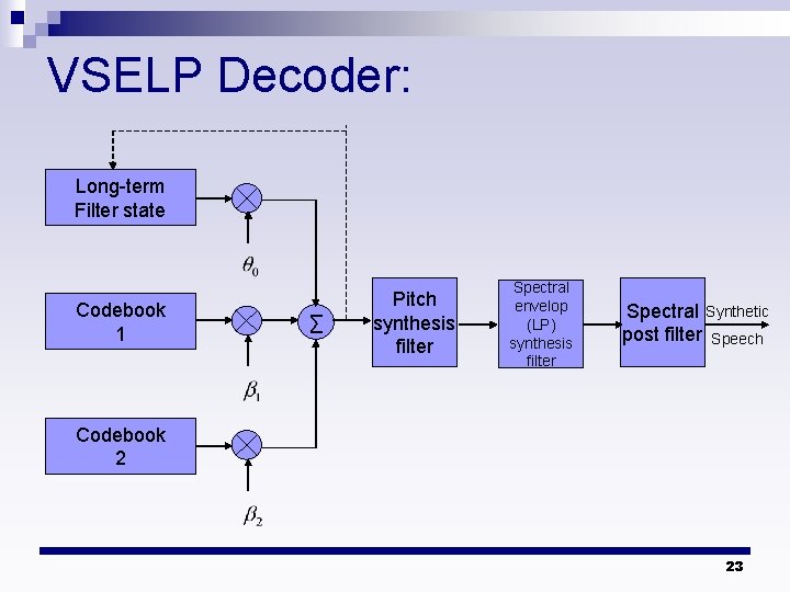
Vector Sum Excited LP: n The VSELP coder and decoder basically differ in method by witch the excitation sequence is formed. n In next block diagram of the VSELP, there are three excitation source. n One excitation is obtained from the pitch period state. n The other two excitation source are obtained from two codebook. 21
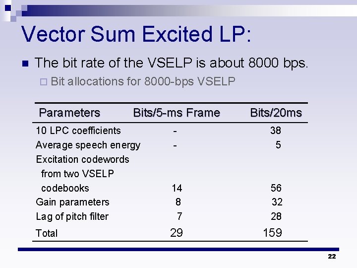
Vector Sum Excited LP: n The bit rate of the VSELP is about 8000 bps. ¨ Bit allocations for 8000 -bps VSELP Parameters Bits/5 -ms Frame Bits/20 ms 10 LPC coefficients Average speech energy Excitation codewords from two VSELP codebooks Gain parameters Lag of pitch filter - 38 5 14 8 7 56 32 28 Total 29 159 22
VSELP Decoder: Long-term Filter state Codebook 1 ∑ Pitch synthesis filter Spectral envelop (LP) synthesis filter Spectral Synthetic post filter Speech Codebook 2 23