
Vocoders 1 The Channel Vocoder analyzer n The
- Slides: 5
Vocoders 1
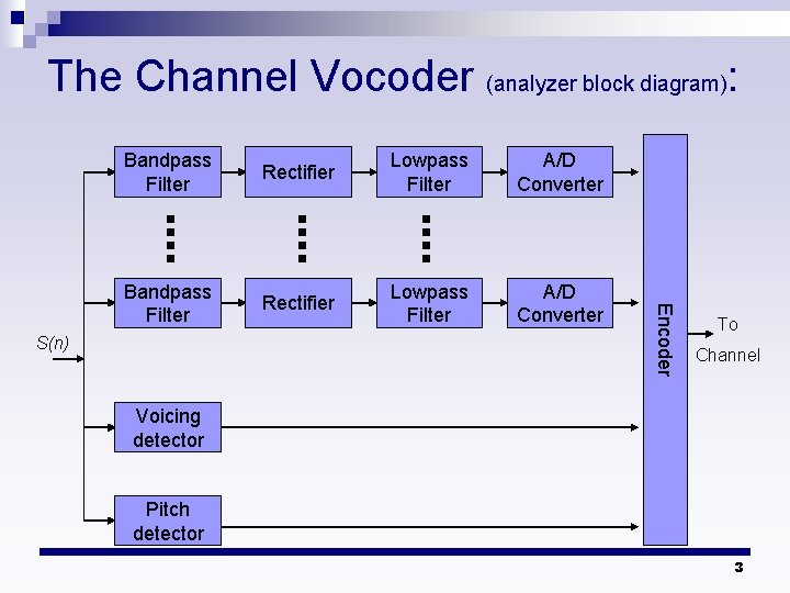
The Channel Vocoder (analyzer): n The channel vocoder employs a bank of bandpass filters, ¨ Each having a bandwidth between 100 HZ and 300 HZ. ¨ Typically, 16 -20 linear phase FIR filter are used. n The output of each filter is rectified and lowpass filtered. ¨ The bandwidth of the lowpass filter is selected to match the time variations in the characteristics of the vocal tract. n For measurement of the spectral magnitudes, a voicing detector and a pitch estimator are included in the speech analysis. 2
The Channel Vocoder (analyzer block diagram): Rectifier Lowpass Filter A/D Converter Bandpass Filter Rectifier Lowpass Filter A/D Converter S(n) Encoder Bandpass Filter To Channel Voicing detector Pitch detector 3
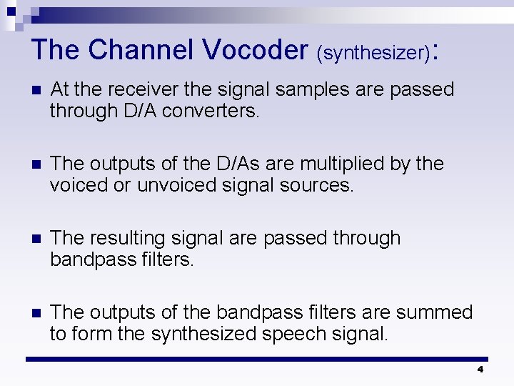
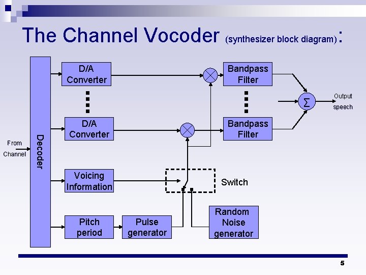
The Channel Vocoder (synthesizer): n At the receiver the signal samples are passed through D/A converters. n The outputs of the D/As are multiplied by the voiced or unvoiced signal sources. n The resulting signal are passed through bandpass filters. n The outputs of the bandpass filters are summed to form the synthesized speech signal. 4
The Channel Vocoder (synthesizer block diagram): D/A Converter Bandpass Filter ∑ Channel Decoder From D/A Converter Output speech Bandpass Filter Voicing Information Switch Pitch period Random Noise generator Pulse generator 5