US 06 CMIC 24 FERMENTATION TECHNOLOGYII UNIT3 Industrial


 One widely used method of assessment")
 BOD test takes 5 days it")


")

")


 increases")


 • Biologically aerated filters are a relatively recent development based")

 • In this treatment method a unit composed")


 reported the successful application of thermophilic anaerobic digestion")

 • In this system (originally developed in the Nether")


 cited an unpublished 1949 survey of American distilleries which showed")


- Slides: 84
US 06 CMIC 24 FERMENTATION TECHNOLOGY-II UNIT-3: Industrial effluent treatment • Nature of effluent generated by fermentation industries - Page no. 313 • Dissolve oxygen as an indicator of water quality. - Page no. 314 • Site surveys, Strength of fermentation effluent. - Page no. 314 -316 • Treatment and disposal of industrial effluents- Sea and rivers, Spray irrigation, Land fills and incineration, disposal of effluent in sewers. - Page no. 316 -318 • Effluent treatment processes: Physical, Chemical and Biological. - Page no. 318 -326 • By products- Distilleries and Breweries. - Page no. 316 -327 Books name: “Principles of fermentation technology, Stanbury, Whitaker and Hall “
Nature of effluent generated by fermentation industries • EVERY fermentation plant utilizes raw materials which are converted to a variety of products. Depending on the individual process, varying amounts of a range of waste materials are produced. • Typical wastes might include unconsumed inorganic and organic media components, microbial cells and other suspended solids, filter aids, waste wash water from cleansing operations, cooling water, water containing traces of solvents, acids, alkalis, human sewage, etc. • Historically, it was possible to dispose of wastes directly to a convenient area of land or into a nearby watercourse. This cheap and simple method of disposal is now very rarely possible, nor is it environmentally desirable. • With increasing density of population and industrial expansion, and greater awareness of the damage caused by pollution, there is a need for treatment and controlled disposal of waste.
• Water authorities and similar bodies have become more active in combating pollution caused by domestic and industrial wastes. • Legislation in all developed countries now regulates the discharge of wastes. • In the UK, much of the legislation pertaining to waste disposal and pollution is embraced by the Environmental Pollution Act 1990 (HMSO, 1990, 1991). • With liquid wastes, it may be possible to dispose of untreated effluents to a municipal sewage treatment works (STW). • Obviously, much will depend on the composition, strength and volumetric flow rate of the effluent. • STWs are planned to operate with an effluent of a reasonably constant composition at a steady flow rate. • Thus, if the discharge from an industrial process is large in volume and intermittently produced it may be necessary to install storage tanks on site to regulate the effluent flow.
• In some locations, municipal sewers are not available or the effluent may be of such a composition that the wastewater treatment company or regulatory authority requires some form of pretreatment before discharge to its sewers. • In these cases an effluent-treatment plant will have to be installed at the factory. • Whatever the pollutant load of the liquid effluent, its discharge to a sewer will be a cost centered activity, and will incur charges from the treatment company. • Normally, fermentation effluents do not contain toxic materials which directly affect the aquatic flora or fauna. Unfortunately, most of the effluents do contain high levels of organic matter which are readily oxidized by microbial attack and so drastically deplete the dissolved oxygen concentration in the receiving water unless there is a large dilution factor.
• Effluent may be treated in a variety of ways, as will be outlined later in this chapter. • In a number of processes it may be possible to recover waste organic material as a solid and sell it as a by-product which may be an animal feed supplement or a nutrient to use in fermentation media. • The marketable by product helps to offset the cost of the treatment process. It is now recognized that water is no longer a cheap raw material. • Obviously the introduction of good "housekeeping will lead to reductions in the volume of water used and the volume of effluent for treatment and final discharge. • Recycling and reuse of materials, waste minimization, waste reduction at source and integrated pollution control are now very important factors to consider in the design and operation of any manufacturing facility, and may be the subject of new legislation in this field.
DISSOLVED OXYGEN CONCENTRATION AS AN INDICATOR OF WATER QUALITY • Since oxygen is essential for the survival of most macroorganisms, it is important to ensure that there adequate levels of dissolved oxygen in rivers, lakes, reservoirs, etc. , if they are to be managed satisfactorily. Ideally, the oxygen concentration should be at least 90% of the saturation concentration at the ambient temperature and salinity of the water. • It is therefore important to know how effluents containing soluble and particulate organic matter can influence the dissolved oxygen concentration.
• • • Biochemical oxygen demand (BOD) One widely used method of assessment is the biochemical oxygen demand (BOD), which is a measure of the quantity of oxygen required for the oxidation of organic matter in water, by micro-organisms present, in a given time interval at given temperature. The oxygen concentration of the a effluent, or a dilution of it, is determined before and after incubation in the dark at 20 C for 5 days. The oxygen decrease can then be determined titrimetrically and the results presented as mg of oxygen consumed per dm 3 of sample. Mineral nutrients and a suitable bacterial inoculum is usually added to the initial sample to ensure optimal growth conditions. This test is only an estimate of biodegradable material, hence recalcitrant or inhibitory compounds might be over looked.
• • • Chemical oxygen demand" (COD) BOD test takes 5 days it may be necessary to resort to the chemical oxygen demand" (COD), a chemical test which only takes a few hours to complete. The test is based on treating the sample with a known amount of boiling acidic potassium dichromate solution for 2. 5 to 4 hours and then titrating the excess dichromate with ferrous sulphate or ferrous ammonium sulphate. The oxidized organic matter is taken as being proportional to the potassium dichromate utilized. Most compounds are oxidized virtually to completion in this test, including those which are not biodegradable. In circumstances where substances are toxic to microorganisms, the COD test may be the only suitable method available for assessing the degree of treatment required.
• The BOD: COD ratios for sewage are normally between 0. 2: 1 and 0. 5: 1. The ratio values for domestic sewage may be fairly steady. • When industrial effluents of variable composition and loading are discharged, the ratio may fluctuate considerably. • Very low BOD-COD ratios will indicate high concentrations of non biodegradable organic matter and consequently biological effluent treatment processes may be ineffective. • A number of alternative tests are available to indicate the oxygen demand of a wastewater, including total organic carbon (TOC) and permanganate value.
SITE SURVEYS • A complete survey of industrial operations is essential for any individual site before an economical waste treatment programme can be planned. • It is desirable to divide the facility into as many units as possible, as knowledge of the various material streams may show unexpected losses of finished product, solvent wastage, excessive use of water or unnecessary contamination of water which might be recycled, recovered or reused within the site. • The factors, and concentrations, (listed in Table) must be known at all production rates under which an individual unit may operate in a representative time period. • The survey may indicate a need for better control of water usage and should identify sources of uncontaminated and contaminated water that might be reused in the factory. • Concentrated waste streams should be kept separate if they contain materials that can be profitably recovered.
Factors to investigate in a site survey Daily flow rate Fluctuations in daily, weekly and seasonal flow BOD/COD Suspended solids Turbidity p. H range Temperature range Odors and tastes Color Hardness Detergents Radioactivity Presence of specific toxins or inhibitors (e. g. heavy metals, phenolics etc. ) • It in also often more economical to treat a concentrate rather than a large volume of a dilute effluent. • The various wastes may be tested in a laboratory and on a pilot scale to assess the best potential methods of chemical and biological treatment.
• Once the p. H of the effluents are known, samples may be mixed to see if a neutral p. H is reached. • A variety of tests may be used to establish methods for reducing salt concentrations, coagulating suspended particles and colloidal materials, and for breaking emulsions. • The commonly used biological tests include respirometry, aeration-flask tests and continuous-culture experiments. • Small flask respirometers and oxygen electrodes are used initially to establish the conditions to use in bio-oxidation of the effluent, and to test for the presence of toxic materials. • Large respirometers (Simpson and Anderson. 1967) are useful for predicting effluent treatment rates and oxygen requirements. • The residues in the flasks can be analyzed to see if there any recalcitrant materials. • The use of laboratory continuous-culture vessels fitted with sludge return pumps and settling tanks can provide detailed information.
• Proposed large-scale operating conditions for feed and aeration rates can be tested and their effectiveness assessed. • The results from all these experiments may help in the design of a full-scale plant. If the survey is comprehensive it should be possible to plan an overall treatment programme for a site and to establish: 1. Water sources which can be combined or reused. 2. Concentrated waste streams which contain valuable wastes to be recovered as food, animal feed, fertilizer or fuel. 3. Toxic effluents needing special treatment, or acids or alkalis needing neutralization. 4. The effluent loading expected under maximum production conditions. 5. The effluent(s) which might be discharged directly, without treatment, on to land or to a watercourse and not cause any pollution. 6. The effluent(s) which might be discharged into municipal sewers.
• • • When all the relevant information has been obtained one can predict the size and type of effluent treatment plant required, and thus its capital and operational costs. This can then be compared with water company charges to treat the waste at an STW with and without on-site treatment. It should be remembered that the water company may insist on onsite treatment before a waste is discharged to the sewer. and will in most cases set consent limits for maximum flow rates and concentrations of specific analytes.
THE STRENGTHS OF FERMENTATION EFFLUENTS • It is already evident from earlier sections of this chapter that the presence of high levels of particulate or soluble organic matter in water will result in potential high BOD. • An initial medium rich in organic matter is converted to biomass and primary and secondary metabolites. • Unfortunately, the product often represents a small proportion of the initial raw material, even in an efficiently operated fermentation. • The spent wastes remaining after the distillation of whisky may account for 90% of the initial raw organic materials, while in an antibiotic fermentation the effluent may represent in excess of 95%. • The BODs of many of these samples are much higher than that of domestic sewage and some may be comparable with strong effluents such as sulphite paper mill liquor.
• It is evident from these data that fermentation effluents may present serious potential pollution problems and may be expensive to dispose of unless well planned processes are used. • A number of steps may be taken to reduce BODs in a process. • Careful selection of raw materials may have a significant effect on the type and quantities of effluent being produced. • The cheapest raw material which meets the nutrient requirements of the micro-organisms may not be ideal if product yield, recovery cost, effluent disposal cost and possible byproduct value are considered together. • The high BOD value of fungal mycelium (40. 000 to 70, 000 mg dm-3 ) would indicate that any biomass should normally be kept separate from the remainder of an effluent and some of it may be sold as a by-product.
• It may also be worthwhile to concentrate liquid fractions, for example, industrial alcohol and distillery stillages (10, 000 to 25, 000 mg dm-3 ) will both produce dried soluble fractions which can be sold. • Metabolites or components of some fermentation effluents may be extremely toxic and polluting and will require complete destruction, for example by chemical or thermal methods, before disposal. • The need for such a treatment strategy will therefore make a significant contribution to the overall cost of the process. One such metabolite is avermectin produced by Streptomyces avermitile fermentations. Here all effluent streams from the process are captured any avermectin present chemically degraded.
Treatment and disposal of industrial effluents • The effluent disposal procedure which is finally adopted by a particular manufacturer is determined by a number of factors. • The most important is the control exercised by the relevant authorities in many countries on the quantity and quality of the waste discharge and the way in which it might be done. The range of effluent-disposal methods which can be considered is: 1. The effluent is discharged to land, river or sea in an untreated state. 2. The effluent is removed and disposed of in a landfill site or is incinerated. 3. The effluent is partially treated on site (e. g. by lagooning) prior to further treatment. 4. Part of the effluent is untreated and discharged as in 1 or 2, the remainder is treated at a sewage works or at the site before discharge.
5. All of the effluent is sent to the sewage works for treatment. 6. All the effluent is treated at the factory before discharge. DISPOSAL Seas and rivers • The simplest way of disposal will be on a sea coast or in a large estuary where the effluent is discharged through a pipeline (installed by the factory or local authorities) extending below the low-water mark. • In such a case there may be little preliminary treatment which depend on the degree of dilution in the sea water. If effluents are to be discharged into a river they must meet the requirements of the local river or drainage authorities. • In Britain there is a Royal Commission standard requiring a maximum BOD (5 days) of 20 mg dm-3 and 30 mg dm-3 of suspended solid matter (the 20: 30 standard).
Stricter standards are often applied. levels of ammoniacal nitrogen may be stipulated. As well as, often stringent upper limits for toxic metals and chemicals which might kill the fauna (particularly fish) and flora, e. g. sulphites, cyanides, phenols, copper, zinc, cadmium, arsenic, etc. Lagoons (oxidation ponds) • Lagoons, holding ponds, oxidation ponds, etc. , may be used by a number of industries if land is available at a reasonable cost. • It is a method often used in seasonal industries where capital • investment in effluent plant is difficult to justify. • The lagoon normally consists of a volume of shallow water • enclosed by watertight embankments. • Oxidation ponds are typically 1 -2 m deep. They can be designed to maintain aerobic conditions throughout, but more commonly decomposition at the surface is aerobic and that nearer the bottom is anacrobic and they are then known as facultative ponds. •
• Oxygen for aerobic degradation is provided both from the surface of the pond, and from algal photosynthesis. • Deeper ponds (known as lagoons) are mechanically agitated to provide aeration. • Lagoons are simple to build and operate, but are expensive in terms of land requirements. • They may be used as the sole method of treatment, incorporating both physical (sedimentation) and biological processes, but the effluent produced may not reach locally acceptable standards. • Alternatively they can provide an initial pretreatment or can be used to 'polish' effluent from secondary treatment processes.
Spray Irrigation • Liquid wastes can be applied directly to land as irrigation water and fertilizer when they are claimed to have a number of beneficial effects on the soil and plants. If this method of disposal is to be used, then it is necessary to have a large area of land near to a manufacturing plant in an area of low to medium rainfall. • Pipeline costs will often restrict use of this technique. • Colovos and Tinklenberg (1962) described the disposal of antibiotic and steroid wastes with BODs of 5000 to 20, 000 mg dm-3 • These wastes were initially chlorinated to lower the BOD and reduce unpleasant odors and then sprayed on to land until the equivalent of 38 mm of rainfall was reached. • This process was repeated at monthly intervals and improved plant growth When appropriate, solid wastes may be spread onto land as a fertilizer and soil conditioner.
• This practice is common with sewage sludges. • Mbagwu and Ekwealor (1990) report the use of spent brewers grains to improve the productivity of fragile soils. • Irrespective of whether the waste is liquid or solid, the concentration of heavy metals and certain organic components will require careful monitoring and control to safeguard the environment and public health. Well disposal • Disused wells, boreholes or mine shafts may provide an ideal, cheap method for disposal when the volume of waste is limited, the underground strata are suitable and the chances of contamination of water supplies utilized by water authorities are negligible. • Melcher (1962) has described the use of wells 500 -m deep for the daily disposal of: .
Acetic acid 900 kg Ammonium acetate 900 kg Sodium acetate 760 kg Sodium chloride 450 kg Sodium and ammonium bromide 225 kg • Methanol, xylene, tars and organic compounds. This mixture had a p. H of 4 to 5 and a COD of 40, 000 to 60, 000 mg dm-3 rising to 100, 000 mg dm-3 and was pumped into the wells at 50 to 100 dm-3 min-1. • Careful hydro geological surveys will be needed to prove that waste disposal in wells will not cause pollution of aquifers and threaten groundwater supplies.
Land filling • Land filling is a disposal method for municipal solid waste (MSW) and industrial waste. It utilizes natural or man made voids (e. g. disused clay pits) into which the waste is deposited. • Both solid and liquid wastes can be deposited depending on restrictions imposed by the site licence. • Strict controls exist on the amount of liquid and toxic materials which can be accepted because of the threat of groundwater pollution if leachate (a liquid having BOD levels up to 30, 000 mg dm-3) escapes from the site. • Leachate is generated from liquid deposited in the site, water entering the site naturally via precipitation or surface run-off and by anaerobic microbial action as organic matter in the landfill is degraded. • Microbial action similar to that in anaerobic digesters leads to the production of landfill gas (LFG) which, being 50 -60 methane can, if collected efficiently, provide a useful source of energy.
Incineration • A number of designs exist for the incineration of solid and/or liquid wastes either on site or at a commercial incinerator, including rotary kilns, fluidized beds and multiple hearth furnaces. • Combustion temperatures need to be carefully controlled to destroy and prevent the formation of dioxins and furans, formation of which occurs at between 300 and 800 , and total destruction is effected at temperatures above 1000 with retention time of 1 second. • Flue gases from the incinerator require cleaning to remove particulates, acid vapours, etc. using electrostatic precipitators, cyclones and wet scrubbers to comply with local environmental protection standards. • Waste disposal by incineration is currently significantly more expensive than land filling, with costs for the disposal of MSW being $37 tonne -1 for incineration compared with $10 tonne-1 for land filling.
Disposal of effluents to sewers Municipal authorities and water treatment companies which accept trade effluents into their sewage systems will want to be sure that: 1. The sewage works has the capacity to cope with the estimated volume of effluent. 2. The effluent will not interfere with the treatment processes used at the sewage works 3. There are no compounds present in the effluent which will pass through the sewage works unchanged and then cause problems when discharged into a water course. It is common practice for local authorities to demand preliminary on-site pretreatment before discharge into sewers to minimize the effects of industrial wastes. The actual pretreatment required will depend on the precise nature of the waste and may range from simple sedimentation to complex chemical and biological processes.
TREATMENT PROCESSES Fermentation wastes may be treated on-site or at an STW by any or all of the three following methods: 1. Physical treatment 2. Chemical treatment 3. Biological treatment Treatment processes may also be described in the following manner: 1. Primary treatment: physical and chemical methods, e. g. sedimentation, coagulation etc. 2. Secondary treatment; biological methods (e. g. activated sludge) conducted after primary treatment. 3. Tertiary treatment; physical, chemical or biological methods (e. g. microstrainers, sand filters and grass plot irrigation) used to improve the quality of liquor from previous stages.
4. Sludge conditioning and disposal; physical, chemical and biological methods. Anaerobic digestion is often used to condition the sludge produced in previous stages. Following dewatering (e. g. by centrifugation using a decanter centrifuge) the sludge can then be disposed of by incineration, land filling, etc. Physical treatment • The removal of suspended solids by physical methods before subsequent biological treatment will considerably reduce the BOD of the resulting effluent. • In nearly all fermentation processes the cells are separated from the liquid fraction in recovery processes, Obviously, biomass processes need not be considered, Yeast cells from other processes may be a marketable product, but microbial cells may not always be marketable, particularly when contaminated with filter aid.
In these instances, when the cells and filter aid are a waste, the recovered material may be dealt with in two basic ways: 1. The waste is disposed of without any further treatment 2. The waste bulk is reduced by mechanical dewatering with a filter press, centrifuge, rotary vacuum filter or belt press. The compressed waste is then incinerated or disposed of in a landfill site. Physical processes installed for primary effluent treatment may include the following stages: 1. Screens, to remove larger suspended and floating matter 2. Comminutors, to reduce particle size, 3. Constant velocity channels (~ 0. 3 ms) for grit removal to prevent damage to plant in later processes 4. Sedimentation tanks for the removal of finer suspended matter. These are generally circular or rectangular continuous flow tanks operating at retention times of 6 -15 hours (and designed to have a minimum retention time of 2 hours), with facility for
the continuous removal of settled sludge. Sedimentation tanks can remove 70% of the incoming suspended solids and, depending on the nature of the waste, up to 40% of its BOD load. They can be operated with or without prior chemical coagulation/flocculation. • Physical processes used in tertiary treatment to produce an effluent of better quality than the 30: 20 standard include microstrainers, slow sand filters, up flow sand filters and rapid gravity sand filters. Throughputs vary between around 3 m-2 day-1 for slow sand liters and 700 m 3 m-2 day-1 for microstrainers. Suspended solids removal is generally 50 - 70% and BOD removal around 30 -50%, depending on the technique used.
Chemical treatment • Fine suspended particles in an effluent may be removed by coagulation and/or flocculation. Coagulation is essentially instantaneous whereas flocculation requires some more time and gentle agitation to achieve "aggregation' of the particles. • Ferrous or ferric sulphate, aluminium sulphate (alum), calcium hydroxide (lime) and polyelectrolyte are often used as chemical coagulants. • A solution of coagulant of the appropriate strength for effective treatment is added to the effluent in a vigorously mixed tank, a precipitate or floc forms almost immediately and carries down the suspended solids to form a sludge. • This sludge may be drawn off, mechanically dewatered and subjected to further treatment. • The flocs formed on coagulation may be small, and will therefore require an extended period to settle, and as a consequence, for a given throughput of effluent a large sedimentation tank will be needed.
• Increasing the particle diameter by encouraging small flocs to coalesce (flocculation) increases the rate of sedimentation and thus for a given throughput, a smaller vessel can be operated. • Polyelectrolyte are commonly used as flocculants, and following addition the effluent is gently mixed (turbulent mixing would break up the flocs) by passage through sinuous flocculation channels, hydro dynamic flocculators or mechanically mixed flocculators. Biological treatment • Most organic waste materials may be degraded biologically. This process may be achieved aerobically or anaerobically in a number of ways. • The most widely used aerobic processes are trickling filters, rotating disc contactors, activated sludge processes and their modifications. The anaerobic processes (digestion, filtration und sludge blankets) are used both in the treatment of specific wastewaters and in sludge conditioning.
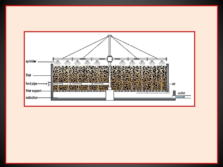
Aerobic processes TRICKLING FILTERS • The trickling filter is not one of filtration, but rather it is a fixed film bio-reactor. Settled effluent to be treated is passed down through a packed bed counter current to a flow of air. • Micro-organisms adhering to the packing matrix adsorb oxygen from the up flowing air and organic matter from the down flowing effluent; organic matter is then metabolized and the effluent stream's BOD reduced. • A conventional trickling filter usually consists of a cylindrical concrete tank 2 to 3 m in depth and 8 to 16 m in diameter. Some filters are rectangular in shape, but a rotary system allows more uniform - hydraulic loading. • The tank is packed with a bed of - stone (usually granite) or special plastic packings, the y bed being under laid with drains.
• The packing material diameter should be 50 to 100 mm to give a specific a surface of around 100 m 3 m-2, and the material should be packed to give a voidage (% air space of total bed volume) of 45 to 55%, which should minimize the risk of the spaces between the packing material becoming a blocked by the microbial film. • Synthetic packing material, although more expensive, has a higher surface area and voidage, allowing higher treatment rates per unit volume of bed and reducing the likelihood of blockages. • The trickling filter is always followed by a secondary sedimentation tank or humus tank to re move suspended matter (e. g. biofilm sloughed off the packing) from the treated effluent. • In conventionally loaded or low-rate filters, the effluent from which the suspended solids have been removed, is fed on to the upper surface of the bed by spray nozzles or mechanical distributor arms.
• The effluent trickles gradually through the bed and a slime layer of biologically active material (bacteria. fungi, algae, protozoa and nematodes) forms on the surface of the support material. • The large surface area created in the bed permits close contact between air flowing upwards through the bed, the descending effluent and the biologically active growth. • The bacteria in the biological film remove the majority of the organic loading. Complex organic materials are broken down and utilized, nitrogenous matter and ammonia are oxidized to nitrates and sulphides and other compounds are similarly oxidized. • The higher organisms (protozoa etc. ) control the accumulation of the biological film (prevents the filter from blocking) and improve the settling characteristics of the solids (humus) discharged with the filter effluent.
• The simple filter is inefficient when operated at abnormally high organic loading rates Initially, there is a very rapid build up of bacteria, fungi and algae at the top of the filter which cannot be controlled by the resident population of worms and larvae. • A trickling filter bed should remove 75 to 95% of the BOD and 90 to 95% of the suspended solids at organic loading rates of 0. 060. 12 kg BOD m-3 day-1 for conventional trickling filtration. • When part of the treated effluent is being recirculated to dilute the feed and increase the hydraulic load placed on the unit the organic loading can be increased to 0. 9 -0. 15 kg BOD m-3 day-1. • To achieve the Royal Commission (20: 30) Standard together with a high degree of nitrification, filters being supplied with domestic sewage should receive organic loading rates of 0. 07 -0 7 -0. 1 kg BOD m-3 day-1 and hydraulic loading rates of 0. 12 -0. 6 m-3 m-3 day-1.
• It is possible to modify the trickling filter to increase the capacity for organic loading by the use of two sets of filters and settling tanks in series, this is known as alternating double filtration (ADF). • Effluent is applied to the first filter at a high hydraulic and organic loading rate, it passes from this filter through the first settling tank and then on to a second filter and settler. After a period of one to two weeks the sequence of the filters is reversed and the second filter receives the higher loading. • In this way heavy film growth is promoted in the first filter to receive the effluent, but when the filter sequence is reversed it becomes nutrient limited, encouraging excess film removal. • Loading rates of 0. 32 - 0. 47 kg BOD m-3 day-1 have been claimed, but recommended rates for design purposes are 0. 15 -0. 26 kg BOD m-3 day-1.
• Alternatively, enclosed deep beds of 3. 5 to 5. 5 m depth may be used in which air is blown through the beds by fans. Loading rates up to 12 times that of the ordinary filter have been claimed.
TOWERS • Trickling filters do not have both a high specific area and a high voidage, they are less suitable for the treatment of large volumes of strong industrial effluents. • Large areas of land would be required for the expensive and extensive traditional filter beds. • Towers, 6 -9 m in height, packed with light weight (40 -80 kg m-3) plastic multi-faced modules or small random packing units have provided to be a space saving and relatively inexpensive solution to the problem. • These packings have a relatively open structure for oxygen transfer (specific surface of 100 -300 m 2 m-3) and high voidage (90 -98 %), but are expensive compared with the conventional filter packings. • They are capable of coping with high BOD loadings.
• At a loading of 3. 2 kg BOD m-3 day-1 a 50% BOD removal may be achieved, and at a 1. 5 kg m-3 day-1 70% removal is possible (Ripley, 1979). • The biological film is similar to that formed on the conventional packing and scouring is due to the hydraulic load applied rather than the predation of higher organisms.
BIOLOGICALLY AFRATED FILTERS (BAFS) • Biologically aerated filters are a relatively recent development based on the trickling filter. They consist s of a packed bed which provides sites for microbial growth through which air is passed but, unlike trickling filters, the reactor volume is flooded with the effluent to be treated which is passed upwards or downwards to the through the reactor (i. e. co or counter currently to air supply) depending on the design. • The packing matrix may be natural (e. g. pumice) or synthetic (e. g. polyethylene), and may be either a fixed structure or randomly packed. • The combination of aeration and filtration allows high rates of BOD and ammonia removal together with solids capture, so that sedimentation tanks may not be required. However, regular backwashing is essential to remove filtered solids and excess biomass.
• Organic loading rates for 90% BOD removal are significantly greater than those obtained for trickling filters, being in the range 0. 7 -2. 8 kg BOD m-3 day-1 (Stephenson et al. , 1993). • They are versatile treatment systems, and of those currently in operation, design capacities vary between 600 and 70, 000 m-3 day-1. • In addition to their use as a secondary treatment process they can also be utilized for tertiary treatment or modified to allow denitrification in a manner similar to that of activated sludge systems.
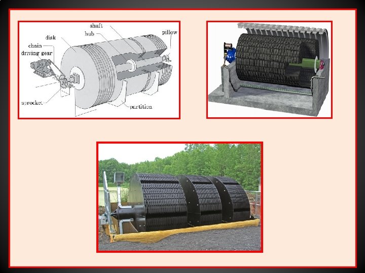
ROTATING BIOLOGICAL CONTACTORS (ROTATING DISC CONTACTORS) • In this treatment method a unit composed of closely spaced discs (2 to 3 m diameter with 1 to 2 cm spacing between discs), on a central drive shaft are rotated slowly (0. 5 to 15 rpm) through the effluent so, that 40 to 50% of the disc surfaces are submerged. • The discs, usually made from synthetic material (e. g. polystyrene, PVC), are arranged in stages or groups separated by baffles to minimize short circuiting or surging and to enhance specific treatment requirements such as nitrification. • The discs may be flat or corrugated to increase surface area. • A microbial film forms on the discs, this is aerated during the exposed part of the cycle and absorbs nutrients during the submerged part.
• Shear forces produced as the discs rotate through the liquid control the thickness of the biofilm, with excess biofilm being sloughed from the discs. • A sedimentation tank following the biological stage is therefore required to remove biological solids. • Loading rates of 13 g BOD m-3 day-1 for domestic sewage and partial treatment of liquids of 400 g BOD m-3 day-1 have been used. To achieve the 20: 30 standard the loading rate should not exceed 6 g BOD m-3 day-1. • Rotating biological contactors are compact, easily covered for health and aesthetic reasons, available as packaged units, simpler to operate under varying loads than trickling filters (the biofilm being wetted at all times) and are easily added onto existing treatment processes. • As such they can provide a cost effective method of on-site treatment.
ROTATING DRUMS • Large rotating drums packed with random plastic packing materials or spheres have been manufactured as a development of rotating discs. • Loading rates for the random packing were similar to those of rotating discs, while plastic spheres used in partial treatment could cope with loads of 6 kg BOD m-3 day-1.
FLUIDIZED-BED SYSTEMS • Fluidized bed reactors in wastewater treatment are relatively recent innovations. • The support matrix (sand, anthracite, reticulated foam) has a large surface area on which the biofilm adheres and thus they are able to operate at high biomass concentrations with high rates of treatment. • This allows strong wastewaters to be treated in small reactors. • They are also useful for the treatment of industrial wastewaters when variable loadings are encountered. • The support matrix is fluidized by the up flow of effluent through the reactor, and the degree of bed expansion is controlled by the flow rate of wastewater. • The treated effluent can thus be decanted off without loss of the support matrix and with careful operation a secondary sedimentation tank may not be needed.
• The support matrix is regularly withdrawn to remove excess biomass. • Fluidized bed systems can be operated aerobically, anaerobically or anoxically for denitrification.
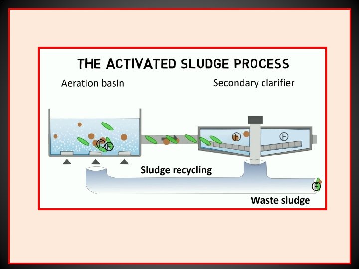
ACTIVATED SLUDGE PROCESSES • The basic activated sludge process consists of aerating and agitating the effluent in the presence of a flocculated suspension of micro-organisms on particulate organic matter -- the activated sludge. • This process was first reported by Arden and Locket (1914) and is now the most widely used biological treatment process for both domestic and industrial wastewaters. • The raw effluent enter a primary sedimentation tank where coarse solids are removed. The partially clarified effluent passes to a second vessel, which can be of a variety of designs, into which air or oxygen is injected by bubble diffusers, paddles, stirrers, surface aerators etc. • Vigorous agitation is used to ensure that the effluent and oxygen are in contact with the activated sludge. After a predetermined residence time of several hours, the effluent passes to a second sedimentation tank to remove the flocculated solids.
• Part of the sludge from the settlement tank is recycled to the aeration tank to maintain the biological activity. • The overflow obtained from the settlement tank should be of a 20: 30 standard or better and be suitable for discharge to inland waters. • The excess sludge is dewatered and dried, to be sold as a fertilizer, incinerated or landfilled. • In conventional activated sludge processes, organic loading rates are 0. 5 -1. 5 kg BOD m-3 day-1 with hydraulic retention times of 5 -14 hours depending on the nature of the wastewater, giving BOD reductions of 90 -95%. • High-rate activated-sludge processes can be used as a partial treatment for strong wastes prior to further treatment or discharge to a sewer and are widely used in the food processing and dairy industries. The organic loading rate is 1. 5 3. 5 kg BOD m-3 day-1 and with hydraulic retention times of only 1 -2 hours. BOD reductions of
• A number of modifications of the basic process can be used to improve treatment efficiency, or for a more specific purpose such as denitrification. • Tapered aeration and stepped feed aeration are used to balance oxygen demand with the amount of oxygen supplied. • Contact stabilization exploits biosorption processes and thereby allows considerable reduction in basin capacity ( 50%) for a given wastewater throughput. • Denitrification (the biological reduction of nitrate to nitrite and on to nitrogen gas under anoxic conditions) can be accomplished in an activated-sludge plant when the first part of the basin is not aerated. • In advanced activated-sludge systems the amount of dissolved oxygen available for biological activity is increased to improve treatment rate.
• One vessel of this d type is the 'Deep Shaft". The 'Deep Shaft consists of a shaft 50 to 150 m deep, separated into a down-flow section (down-comer) and an up-flow section (riser). • The shaft may be 0. 5 to 10 m diameter, depending on capacity. • Fresh effluent is fed in at the top of the 'Deep Shaft' and air is injected into the down-flow section at a sufficient depth to make the liquid circulate at 1 to 2 m s-1. • The driving force for circulation is created by the difference in density (due to air bubble volume) between the riser and downflow sections. • For starting up, circulation of liquid is stimulated by injecting air at the same depth in the riser. • BOD removal rates of 90% are achievable at organic loadings of 3. 7 -6. 6 kg BOD m-3 day-1 at hydraulic retention times of 1. 17 -1. 75 hours (Gray, 1989)
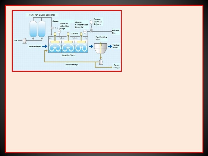
• Sludge reproduction was found to be much less than that for conventional sewage treatment processes. • Two types of pure oxygen systems have also been developed to increase the rate of oxygen transfer: 1. Closed systems which operate in oxygen rich atmospheres. 2. Open systems employing fine bubble diffusers. • An example of the closed system is the UNOX. Process developed by the Union Carbide Corporation in the U. S. A. , and marketed in the U. K. by Wimpey Unox. • Organic loading rates (when treating municipal wastewater) are 3 -4 times higher than those of aerated systems at 25 -4. 0 kg BOD m-3 day-1 • The UNOX process has been successfully used for the treatment of brewery wastewaters containing 2000 mg BOD dm-3 flow rates of 2269 m-3 day-1 with a 6. 6 hour retention time.
• Its • • • The VITOX aeration system developed by the British Oxygen Company is an example of an open tank oxygenation system. main advantage is that it can be used in existing aeration tanks either to replace or upgrade conventional aeration without the need to replace or modify existing units. Oxygenation in achieved by pumping settled wastewater high pressure through a venturi where oxygen is injected. Turbulence and high pressures thus created ensure high levels of oxygen dissolution. The flexibility of this system means that it is particularly useful for the treatment of high strength intermittently produced wastewaters such as those generated by food processing industries.
Anaerobic treatment • Anaerobic treatment of waste organic materials originated with the use of septic tanks and Imhoff tanks, which have now been replaced by a variety of high-rate digesters. • Loehr (1968) has listed the following reasons for using anaerobic processes for waste treatment: 1. Higher loading rates can be achieved than are possible for aerobic treatment techniques. 2. Lower power requirements may be needed per unit of BOD treated. 3. Useful end-products such as digested sludge and/or combustible gases may be produced. 4. Organic matter is metabolized to a stable form. 5. There is an alteration of water-binding characteristics to permit rapid sludge dewatering.
6. The reduced amount of microbial biomass leads to easier handling of sludge. 7. Low levels of microbial growth will decrease the possible need for supplementary nutrients with nutritionally unbalanced wastes. ANAEROBIC DIGESTION • Large volumes of wet sludge which are produced in primary and secondary sedimentation tanks may have to be reduced in volume before disposal. • This volume of sludge can be reduced by anaerobic digestion. • In sludges containing 20000 -60, 000 mg dm-3 solid matter, 80% of the degradable matter may be digested which will reduce the solids content by 50%.
• • During anaerobic digestion acid fermenting bacteria degrade the waste to free volatile fatty acids, mainly acetic and propionic acid, which are then converted to methane (60 %) and carbon dioxide (40%). The gas produced (biogas) is a very useful by product, and can be burnt as a heating fuel, fed to gas engines to generate electricity or used as a vehicle fuel. As well as being used in sludge digestion and conditioning, anaerobic digesters are also used directly in the treatment of many high strength wastewaters, for example from the food and agricultural industries. A number of anaerobic processes have been developed, completely mixed reactors (often these are simply described as anaerobic digesters) with or without sludge recycle, anaerobic filters, up-flow anaerobic sludge blankets (UASB) and anaerobic fluidized beds are the most common.
Two stage anaerobic treatment systems utilizing a short retention time completely mixed acidification reactor followed by a UASB methanogenic reactor have been reported. • Benefits claimed include improved reliability, higher BOD/COD reductions and greater methane productivity. •
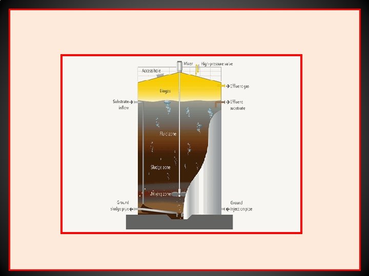
ANAEROBIC DIGESTERS • The digester tanks used for this process may be up to 12, 000 -m 3 volume and equipped with heating coils for accurate temperature control normally in the mesophilic range (25°-38°, usually 28°-32° in anaerobic digestion) to increase the rate of digestion, which is also improved by mechanical agitation. • Some digesters are operated thermophilically (50°-70°, usually 55°- 65° in anaerobic digestion) to increase the rate of degradation and biogas production, though much of the extra gas produced will be consumed in maintaining the digester temperature. • The use of thermophilic anaerobic digestion has been investigated for the treatment of high strength (16 -25 g COD dm-3 ). low p. H (- 3. 8) and high temperature winery effluents.
• Wiegant et al. (1985) reported the successful application of thermophilic anaerobic digestion of vinasse in completely mixed and UASB reactors, although methane production was found to decrease at high loading rates due to the presence of inhibitory compounds. • Most digesters operate on a semi-continuous basis with the appropriate volume of digested material being removed and replaced with fresh' material on a daily basis.
ANAEROBIC FILTERS • In anaerobic filters, as with the aerobic filters, there is a microbial film growing on an inert support. • Anaerobic filters may be operated in an upflow or downflow mode, and a wide variety of packings are used; both natural and synthetic. • The first full-scale anaerobic filters were constructed in the 1970 s and in 1982 the Bacardi Corporation brought into operation a 100, 000 m-3 plant to treat distillery effluents. • Many other effluents are found to be amenable to treatment using anaerobic filter systems, antibiotic fermentation wastes, citric acid fermentation wastes, yeast production wastewater and brewery and winery wastewaters, molasses distillery slops and fermentation and pharmaceutical wastes.
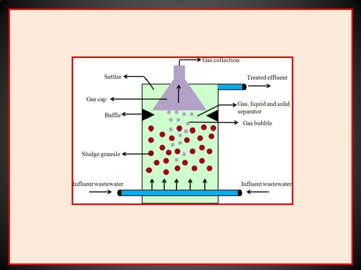
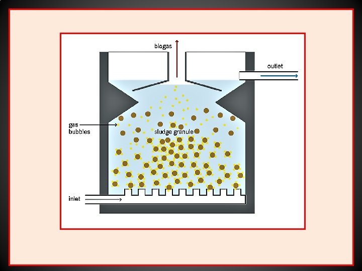
UP-FLOW ANAEROBIC SLUDGE BLANKETS (UASB) • In this system (originally developed in the Nether lands) high levels of active biomass are retained in the reactor by flocculation. • No support media is added to the reactor, instead the flocculated sludge develops in the reactor and acts as a fluidized bed. • Feed is pumped through the bed (the sludge blanket), above which fine particles flocculate and settle back to the blanket as sludge, thus preventing washout of organisms. • Anaerobic sludge blankets have been found to be effective in the treatment of many wastewaters, including sugar-beet wastes, domestic sewage, slaughterhouse wastes, agricultural wastes, brewery wastes, winery wastes and Distillery wastes.
BY-PRODUCTS • The marketing of wastes from fermentation processes has been established for at least 200 years. By the 1700, brewers grains, spent hops and surplus yeast from larger breweries were accumulating in sufficient quantities for specialized trades to develop (Mathias, t 1959). • In any fermentation recovery process there is a need to recognize whethere is a potential marketable waste and, if necessary, to develop a market. • Obviously the marketability and cost of roclamation of by-products will be very important in deciding upon a policy of waste recovery. • Under favorable market conditions has been claimed that the profit on animal feed by products from a completely Integrated distillery may almost pay the cost of the grain (Blaine, 1965).
• Some microbial processes yield residues which are difficult or impossible to sell (Blaine, 1965). • In these processes it may be possible, and worth while, to change to low residue raw materials such as refined sugars or other pure compounds as sources of soluble nutrients. Distilleries • In grain based distilleries it has been common practice to recover spent grain and stillage, the waste liquor after the alcohol has been distilled off. • The stillage is first passed through screens with 1 -mm openings. The screenings are then dewatered with mechanical filter presses and dried in rotary driers. • This product is termed Distillers Dried Grains (light grains). The screened stillage is concentrated in evaporators to give 25 to 35% solids in a thick syrup.
• Stillages which have been pre filtered may be concentrated to 35 to 50% solids. This syrup can then be mixed with the pressed screenings and dried to give Distillers Dried Grains with Soluble (dark grains). • Alternatively the evaporated stillage may be dried completely in drum driers to produce Distillers Dried Soluble. Dark and light grains and dried soluble have all been used as animal-feed supplements. • Flachowsky et al. (1990) report their use following chemical treatment as a replacement feed for sheep. Dried soluble have also been used as a medium adjunct in the preparation of antibiotics. • In distilleries using cane molasses as a feedstock, evaporated spent wash has been used as a fuel for boilers, It has proved worth while to recover potassium salts from sugar beet stillage. • The market for the evaporated product must be considered within a range of 50 km of the evaporation plant.
• Borut (1953) cited an unpublished 1949 survey of American distilleries which showed that 85% of the stillage solids were being recovered as dried feeds, 14% solids as wet grains and only 1% waste. • In recent years the traditional distillers' by-products from stillage have become increasingly uneconomic. • A number of processes to produce SCP from stillage using Geotrichum candidum, Candida utilis or Candida tropicalia have been evaluated.
Breweries • The three marketable wastes from breweries are spent grain, spent hops and yeast. The spent grain is recovered from the mash tun and is then sold as animal feed either after pressing in a wet state or after drying in rotary driers. • Alternatively, the wet grain may be used in the preparation of silage for cattle. The possible markets for hops are restricted. Some are used as a fertilizer or as a low-grade fuel. • Yeast can be separated from beer by filtration or centrifuging. The yeast slurry is then dried in drum driers. Some of the yeast may be mixed with brewers' spent grains to produce a feed material with a slightly higher protein content than normal brewers' grains. • The yeast may also be used directly as a source of vitamins. If it is to be used as a human food it must be debittered to remove the hop bitter substances absorbed on to the yeast cells.
• The cells are then washed in an alkaline solution, washed with water and drum dried. Although bakers' yeast was originally obtained as a brewery by-product, this market has diminished considerably. • Most bakers' yeast is now produced directly by a distinct production process. • Dewatered sludge from brewery wastewater treatment operations has been reported to increase agricultural yields when used as fertilizer. • Lyons (1983) reports on the potential use of brewery effluents as a feedstock for fuel and industrial ethanol production.
Amino acid wastes The main wastes from glutamic acid or lysine fermentations are cells, a liquor with a high amino acid content which can be used as an animal-feed supplement, and the salts removed from the liquor by crystallization, which is a good fertilizer. Fuel alcohol wastes The stillage from ethanol production and wastes from starchy fermentations are, following concentration, saleable as an animal feed supplement Wastes from sugar fermentations and distillation can be digested anaerobically and the methane generated used as an energy source. Faust al. (1983) also suggest the use of CO 2 rich off gases in the food and beverage industries.