Transformer Topic covered Working principle of single phase


 = Φ / (1/4 f) =")


 is defined as the ratio of the EMF in the")

 Where, K = constant This constant K is")

 Losses (Pi) 1. Hysteresis losses 2. Eddy current losses Pi")


A MI 1 (0 -5)")


- Slides: 69
-: Transformer : -
-: Topic covered : � � � Working principle of single phase transformer. Construction Types of Transformer. Emf Equation of Transformer on LOAD.
TRANSFORMER Transformer is static device which transfers electric energy from one circuit to another circuit with desirable change in voltage or current by keeping frequency constant.
PRINCIPLE OF TRANSFORMER � � It works on the principle of mutual induction, According to which an e. m. f is induced in a coil when current in the neighboring coil changes. . 11/15/99 Norm Herr (sample file)
PRINCIPLE OF TRANSFORMER
CONSTRUCTION 1. An elementary transformer consists of a soft iron or silicon steel core and two windings, placed on it. 2. The windings are insulated from both the core and each other. The core is built up of thin soft iron. 3. The winding connected to the supply main is called the primary and the winding connected to the load circuit is called the secondary. 9/9/2021 6
Principle of working
Working 1. When the primary winding is connected to an ac supply mains, current flows through it. Since this winding links with an iron core, so current flowing through this winding produces an alternating flux in the core. Since this flux is alternating and links with the secondary winding also, so induces an emf in the secondary winding. 11/15/99 Norm Herr (sample file)
2. The frequency of induced emf in secondary winding is the same as that of the flux or that of the s supply voltage. 3. The induced emf in the secondary winding enables it to deliver current to an external load connected across it. Thus the energy is transformed from primary winding to the secondary winding by means of electromagnetic induction without any change in frequency. 11/15/99 Norm Herr (sample file)
4. The flux Ø of the iron core links not only with the secondary winding but also with the primary winding, so produces self-induced emf in the primary winding. 5. This induced in the primary winding opposes the applied voltage. In this way the induced emf in the primary winding limits the primary current 11/15/99 Norm Herr (sample file)
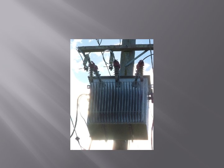
Construction of Transformer � 1. 2. 3. 4. 5. 6. 7. Main parts of transformer Laminated Steel core. Windings of the transformer Tank Terminal Bushings Conservator Buchholz Relay Explosion Vent
Laminated Steel Core 1. The core is made up of magnetic material which has high permeability and low magnetic reluctance which helps to produce a strong magnetic field. 2. The core is in the form of thin steel sheets (stampings) which are electrically isolated from each other.
Why do we laminate the core? Eddy currents are large & losses are great I S
Why do we laminate the core? Eddy currents are small & losses are reduced I S
Windings of the Transformer � � Concentric Type Sandwich Type
Winding types 1. Concentric windings: 1. Low Voltage windings are placed near to the core and high voltage windings are placed after low voltage winding. Concentric Higher voltage closest to Iron
Winding types 2. Sandwitch or pancake High voltage winding and low voltage winding are wound in the form of pancakes and then they interleaved. The top and bottom windings which are near the yoke are of low voltage winding only
Transformer Tank
Transformer Tank 1. 2. The whole transformer assembly is placed in a metal tank and immersed in oil which serves purpose of providing insulation and cooling. Cooling tubes are provided to increase the surface area of the tank for more effective cooling
Terminal Bushings
Transformer with conservator
Conservator � � � The conservator is air tight cylindrical metal drum supported on the transformer tank. This drum is connected with pipe to the transformer tank and always partially filled with oil. The expansion and contraction of the oil in the main tank with changes of temperature is now taken up by the conservator.
Buchholz Relay
Buchholz Relay � � � This is a protective device mounted in the pipe line connecting to the main tank to the conservator. Due to excessive heat developed during the fault condition the oil in the tank gets decomposed and different types of the gases are liberated. These gases operate the buchholz relay which gives alarm to the operator.
Buchholz Relay
Explosion Vent
TYPES OF TRANSFORMER Based on voltage 1. Step up transformer 2. Step down transformer Based on construction 1. Core type transformer 2. Shell type transformer 3. Berry type transformer Based on applications 1. Instrument Transformer 2. Auto transformer 3. Leakage Transformer 4. Resonant Transformer 5. Poly phase Transformer Based on supply 1. Single phase Transformer 2. Three phase Transformer
Core and shell type transformer
Berry type transformer
-: EMF Equation of Transformer: Let N 1 = No. of turns in primary N 2 = No. of turns in secondary Φm = Maximum flux in core in webers = Bm × A f = Frequency of a. c. input in Hz flux increases from its zero value to maximum value Φm in one quarter of the cycle
∴ Average rate of change of flux (dΦ/dt) = Φ / (1/4 f) = 4 f Φm Wb/s or volt Now, rate of change of flux per turn means induced e. m. f. in volts. i. e. e = N dΦ/dt ∴ Average e. m. f. /turn = 4 f Φm volt If flux Φ varies sinusoidally, then r. m. s. value of induced e. m. f. is obtained by multiplying the average value with form factor. Form factor =r. m. s. value/ avg. value = 1. 11
∴ r. m. s. value of e. m. f. /turn = 1. 11 × 4 = 4. 44 f Φm volt • Now, r. m. s. value of the induced e. m. f. in the whole of primary winding having N 1 no of primary turns = (induced e. m. f/turn) × No. of primary turns • E 1 = 4. 44 f N 1 Φm = 4. 44 f N 1 Bm A. . (1) Where A= area of core Similarly, r. m. s. value of the e. m. f. induced in secondary is,
Ratios in transformer � 1. Transformation ratio � 2. Voltage ratio � 3. Current ratio � 4. Turns ratio
1. Transformation Ratio (K) is defined as the ratio of the EMF in the secondary coil to that in the primary coil. K = E 2/E 1 = (4. 44(Φm)f. N 2)/(4. 44(Φm)f. N 1) Therefore, K = E 2/E 1 = N 2/N 1…. (1)
Now, V 1 = E 1 + voltage drop E 2 = V 2 + voltage drop Due to the resistance in the windings and some leakage flux, there is some loss in voltage. This is called as Voltage Drop. But, in ideal case, voltage drop can be neglected. Hence, V 1 = E 1 E 2 = V 2 Hence, E 2/E 1 = V 2/V 1…. . (2) Also, in a transformer, the power across the primary as well as the secondary winding is same. Hence, V 1. I 1 = V 2. I 2 V 1/V 2 = I 2/I 1……. . (3) Now, combining (1), (2) & (3), we get, K = E 2/E 1 = N 2/N 1 = V 2/V 1 = I 2/I 1
• Voltage Transformation Ratio (K) Where, K = constant This constant K is known as voltage transformation ratio. If N 2 > N 1, E 2>E 1 i. e. K > 1, then the transformer is called step-up transformer. If N 2 < N 1, E 1>E 2 i. e. K < 1, then the transformer is called step-down transformer.
Current Ratio. It is the ratio of primary current to the secondary current. I 2/I 1= K = E 2/E 1 Voltage Ratio. It is the ratio of primary voltage to the secondary voltage V 1/V 2=1/K=E 2/E 1 Turns ratio. It is the ratio of primary no of turns to the secondary no of turns. N 1/N 2=1/K=E 2/E 1
Losses in transformer Core(Iron) Losses (Pi) 1. Hysteresis losses 2. Eddy current losses Pi = PH + PE Copper Loss (I²R loss) Pcu = I 1²R 1 + I 2²R 2
Voltage Regulation. The voltage regulation is the percentage of voltage difference between no load and full load secondary voltages of a transformer with respect to its full load secondary voltage. Expression of Voltage Regulation of Transformer
When load is not connected the secondary voltage is equal to primary induced emf E 2 • As load current increases, the voltage drops tend to increase V 2 and drops more and more. In case of lagging power factor V 2 < E 2 and we get positive voltage regulation, while for leading power factor E 2 < V 2 and we get negative voltage regulation. • The voltage drop should be as small as possible hence less the regulation better is the performance of a transformer.
Transformer Efficiency Transformer efficiency is defined as ratio of output power to the input power Types of losses incurred in a transformer: Copper I 2 R losses Core losses Therefore, for a transformer, efficiency may be calculated using the following: Electrical Machines
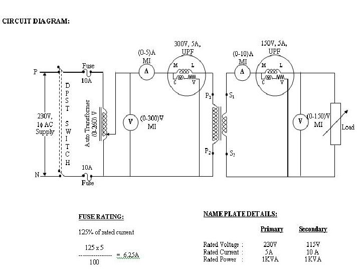
LOAD TEST ON A SINGLE PHASE TRANSFORMER AIM: To conduct load test on single phase transformer and to find efficiency and percentage regulation. PROCEDURE: 1. Connections are made as per the circuit diagram. 2. After checking the no load condition, minimum position of auto transformer and DPST switch is closed. 3. Ammeter, Voltmeter and Wattmeter readings on both primary side and secondary side are noted. 4. The load is increased and for each load, Voltmeter, Ammeter and Wattmeter readings on both primary and secondary sides are noted. Again no load condition is obtained and DPST switch is opened.
APPARATUS REQUIRED: S. No. Apparatus Range Type Quantity (0 -10)A MI 1 (0 -5) A MI 1 (0 -150)V MI 1 (0 -300) V MI 1 (300 V, 5 A) Upf 1 (150 V, 5 A) Upf 1 1 Ammeter 2 Voltmeter 3 Wattmeter 4 Auto Transformer 1 , (0 -260)V - 1 5 Resistive Load 5 KW, 230 V - 1 6 Connecting Wires 2. 5 sq. mm Copper Few
Observation Table Sr. no Primary V 1 1 2 3 4 5 I 1 Secondary W 1 V 2 Input Power = W 1 x MF W 2 Output Power= W 2 x MF Efficie ncy % Regulati on
FORMULAE: Output Power = W 2 x Multiplication factor Input Power = W 1 x Multiplication factor Output Power Efficiency % = ---------- x 100% Input Power VNL - VFL (Secondary) Regulation R % = -------------x 100% VFL
MODEL GRAPHS:
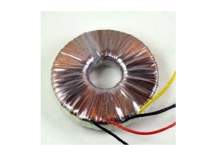
What is Auto Transformer ? • Auto transformer is kind of electrical transformer where primary and secondary shares same common single winding. So basically it’s a one winding transformer.
Auto Transformer
Types of AUTOTransformer • Step UP Transformer : A transformer in which Ns>Np is called a step up transformer. A step up transformer is a transformer which converts low alternatic voltage to high alternatic voltage.
• Step DOWN Transformer : A transformer in which Np>Ns is called a step down transformer. A step down transformer is a transformer which converts high alternating voltage to low alternating voltage.
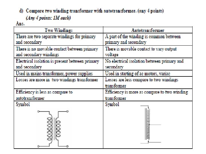
Copper saving in Auto transformer • The same output and voltage transformation ratio an autotransformer requires less copper than the 2 winding transformer
Advantages • An autotransformer requires less Cu than a two-winding transformer of similar rating. • An autotransformer operates at a higher efficiency than a two-winding transformer of similar rating. • An autotransformer has better voltage regulation than a two-windingtransformer of the same rating. • An autotransformer has smaller size than a two-winding transformer of the same rating. • An autotransformer requires smaller exciting current than a two-windingtransformer of the same rating. • Size of the machine is small • Cost of autotransformer is less compred to teo winding transformer
DISADVANTAGES • There is a direct connection between the primary and secondary. Therefore, the output is no longer d. c. isolated from the input. • An autotransformer is not safe for stepping down a high voltage to a low voltage. As an illustration.
• If an open circuit develops in the common portion of the winding, then full-primary voltage will appear across the load. In such a case, any one coming in contact with the secondary is subjected to high voltage. This could be dangerous to both the persons and equipment. For this reason, autotransformers are prohibited for general use. • The short-circuit current is much larger than for the two-winding transformer of the same rating. So that a short-circuited secondary causes part of the primary also to be short-circuited. This reduces the effective resistance and reactance.
APPLICATION • Autotransformers are used to compensate for voltage drops in transmission and distribution lines. When used for this purpose, they are known as booster transformers. • Autotransformers are used for reducing the voltage supplied to a. c. motors during the starting period. • Autotransformers are used for continuously variable supply.
• On long rural power distribution lines, special autotransformers with automatic tap-changing equipment are inserted as voltage regulators, so that customers at the far end of the line receive the same average voltage as those closer to the source. The variable ratio of the autotransformer compensates for the voltage drop along the line. • In control equipment for 1 -phase and 3 -phase electrical locomotives.
Why transformer should not be connected to D. C supply Transformer must not be connected to a direct source. If the primary winding of a transformer is connected to a dc supply mains, the flux produced will not vary but remain constant in magnitude and therefore no emf will be induced in the secondary winding except at the moment of switching on. Thus the transformer can not be employed for raising or lowering the dc voltage. Also there will be no back induced emf in the primary winding and therefore a heavy current will be drawn from the supply mains which may result in the burning out of the winding.
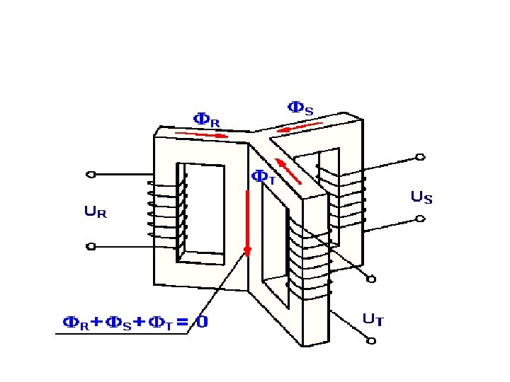
Three-phase Transformers • The transformers may be inherently 3 -phase, • having three primary windings and three secondary windings mounted on a 3 -legged core. • The same result can be achieved by using three singlephase transformers connected together to form a 3 phase transformer bank. • When three single-phase transformers are used to transform a 3 -phase voltage, the windings can be connected in several ways. the ratio of the 3 -phase input voltage to the 3 -phase output voltage depends not only upon the turns ratio of the transformers, but also upon how they are connected.
3 phase Transformer connections • By connecting three single phase transformers 1. Star- Star connection 2. Delta- Delta connection 3. Star – Delta connection 4. Delta – Star connection
Star- Star connection
Delta - Delta connection
Star- Delta connection
Delta - Star connection