
Switching Mode Power Supply for Sputter Ion Pumps


- Slides: 20
Switching Mode Power Supply for Sputter Ion Pumps Final project of bachelor Electrotechnical and Computer science engineering. Instituto Politécnico de Leiria Author: Supervisors: Alexandre Mateus Correia, Nº 2140732 Ihor Koval, Nº 2140233 Interlocks, Controls and Monitoring & Vacuum Group Technology Department Dr. Telmo Fernandes (IPL/IT-Lr) Mr. Gregory Pigny (ICM) November 2020 1
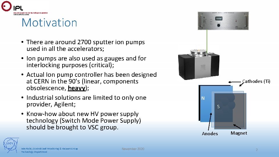
Motivation • There around 2700 sputter ion pumps used in all the accelerators; • Ion pumps are also used as gauges and for interlocking purposes (critical); • Actual Ion pump controller has been designed at CERN in the 90’s (linear, components obsolescence, heavy); • Industrial solutions are limited to only one provider, Agilent; • Know-how about new HV power supply technology (Switch Mode Power Supply) should be brought to VSC group. Interlocks, Controls and Monitoring & Vacuum Group Technology Department November 2020 Cathodes (Ti) N S Anodes Magnet 2
Goals • Replace the present linear power supplies with a switching mode power supply (SMPS); • Produce a energetically efficient and compact solution; • Current usage and measurement between 10 n. A – 100 m. A; • Reliable, motivated by a long working period (24 h/7); • Build step by step in order to use modules already in the market that can be incorporated in our project (if needed). Interlocks, Controls and Monitoring & Vacuum Group Technology Department November 2020 3
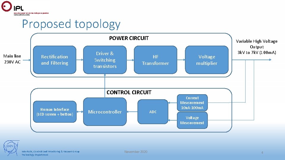
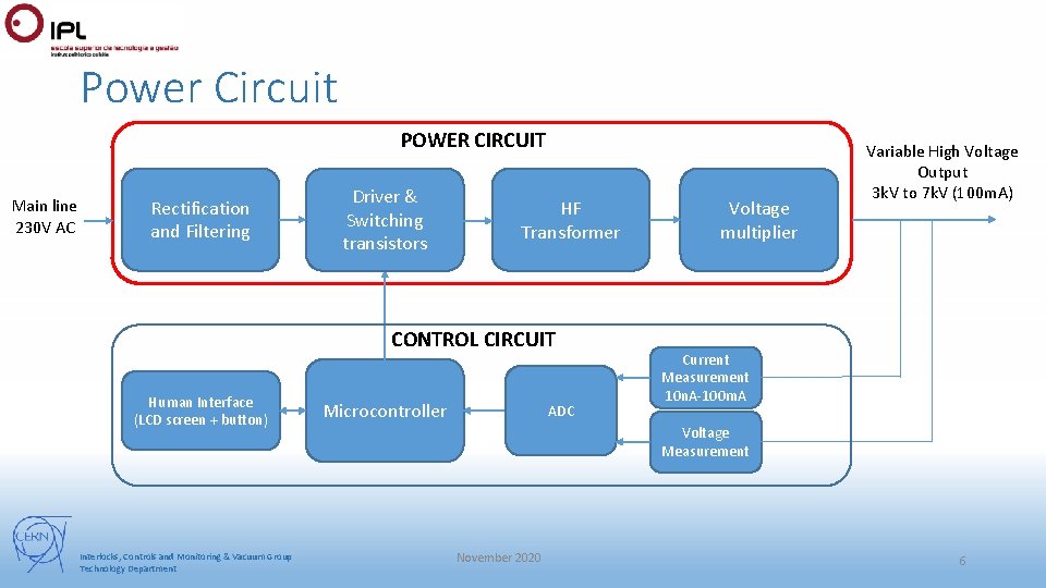
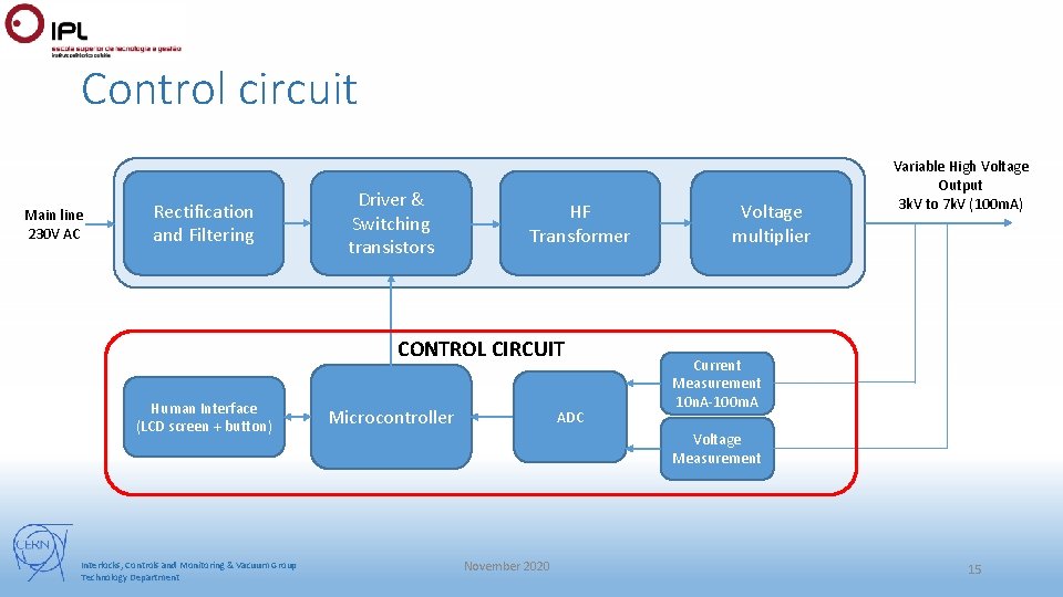
Proposed topology POWER CIRCUIT Main line 230 V AC Rectification and Filtering Driver & Switching transistors HF Transformer CONTROL CIRCUIT Human Interface (LCD screen + button) Interlocks, Controls and Monitoring & Vacuum Group Technology Department Microcontroller ADC Voltage multiplier Variable High Voltage Output 3 k. V to 7 k. V (100 m. A) Current Measurement 10 n. A-100 m. A Voltage Measurement November 2020 4
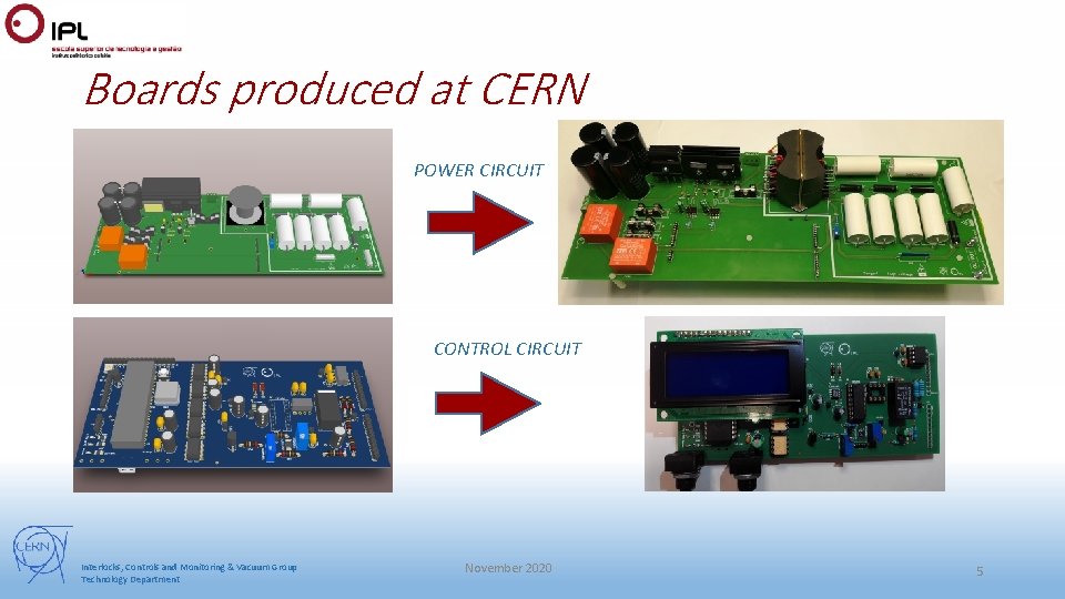
Boards produced at CERN POWER CIRCUIT CONTROL CIRCUIT Interlocks, Controls and Monitoring & Vacuum Group Technology Department November 2020 5
Power Circuit POWER CIRCUIT Main line 230 V AC Rectification and Filtering Driver & Switching transistors HF Transformer CONTROL CIRCUIT Human Interface (LCD screen + button) Interlocks, Controls and Monitoring & Vacuum Group Technology Department Microcontroller ADC Voltage multiplier Variable High Voltage Output 3 k. V to 7 k. V (100 m. A) Current Measurement 10 n. A-100 m. A Voltage Measurement November 2020 6
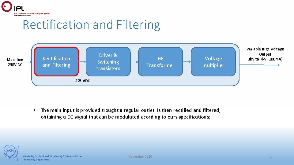
Rectification and Filtering Main line 230 V AC Driver & Switching transistors Rectification and Filtering HF Transformer Voltage multiplier Variable High Voltage Output 3 k. V to 7 k. V (100 m. A) 325 VDC • The main input is provided trought a regular outlet. Is then rectified and filtered, obtaining a DC signal that can be modulated acording to ours specifications; Interlocks, Controls and Monitoring & Vacuum Group Technology Department November 2020 7
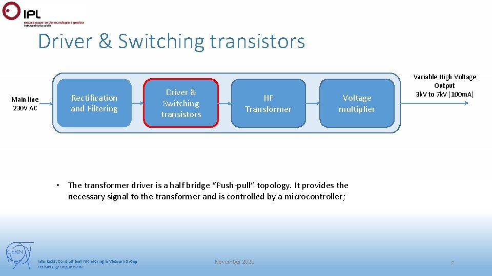
Driver & Switching transistors Main line 230 V AC Rectification and Filtering Driver & Switching transistors HF Transformer Voltage multiplier Variable High Voltage Output 3 k. V to 7 k. V (100 m. A) • The transformer driver is a half bridge “Push-pull” topology. It provides the necessary signal to the transformer and is controlled by a microcontroller; Interlocks, Controls and Monitoring & Vacuum Group Technology Department November 2020 8
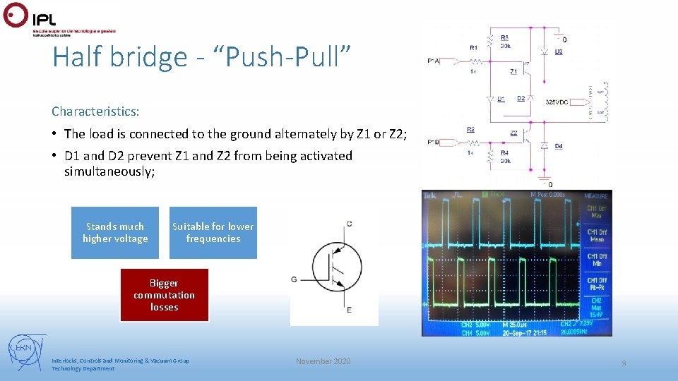
Half bridge - “Push-Pull” Characteristics: • The load is connected to the ground alternately by Z 1 or Z 2; • D 1 and D 2 prevent Z 1 and Z 2 from being activated simultaneously; Stands much higher voltage Suitable for lower frequencies Bigger commutation losses Interlocks, Controls and Monitoring & Vacuum Group Technology Department November 2020 9
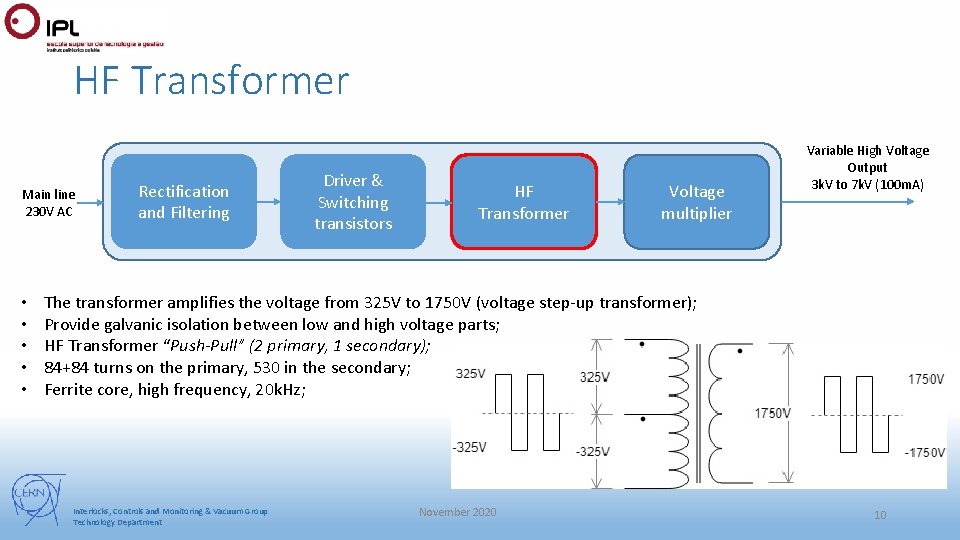
HF Transformer Main line 230 V AC • • • Rectification and Filtering Driver & Switching transistors HF Transformer Voltage multiplier Variable High Voltage Output 3 k. V to 7 k. V (100 m. A) The transformer amplifies the voltage from 325 V to 1750 V (voltage step-up transformer); Provide galvanic isolation between low and high voltage parts; HF Transformer “Push-Pull” (2 primary, 1 secondary); 84+84 turns on the primary, 530 in the secondary; Ferrite core, high frequency, 20 k. Hz; Interlocks, Controls and Monitoring & Vacuum Group Technology Department November 2020 10
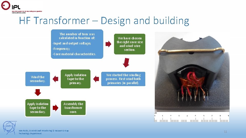
HF Transformer – Design and building The number of turn was calculated in function of: -Input and output voltage; -Frequency; -Core material characteristics. Wind the secondary. Apply isolation tape to the primary. We have chosen the right core size and wire section. We started the winding process. First wind both primaries (in parallel). Assembly the transformer core. Interlocks, Controls and Monitoring & Vacuum Group Technology Department 11
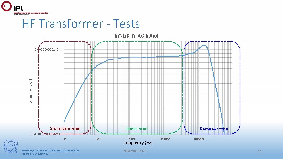
HF Transformer - Tests BODE DIAGRAM Gain (Vo/Vi) 8. 000001484 Saturation zone Linear zone Resonant zone 0. 80000014841 10 Interlocks, Controls and Monitoring & Vacuum Group Technology Department 1000 Frequency (Hz) November 2020 100000 12
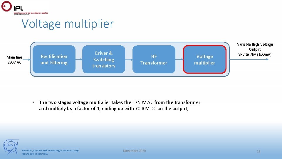
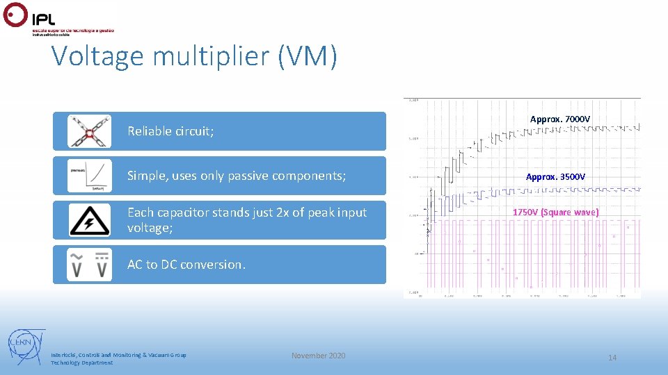
Voltage multiplier Main line 230 V AC Rectification and Filtering Driver & Switching transistors HF Transformer Voltage multiplier Variable High Voltage Output 3 k. V to 7 k. V (100 m. A) • The two stages voltage multiplier takes the 1750 V AC from the transformer and multiply by a factor of 4, ending up with 7000 V DC on the output; Interlocks, Controls and Monitoring & Vacuum Group Technology Department November 2020 13
Voltage multiplier (VM) Approx. 7000 V Reliable circuit; Simple, uses only passive components; Each capacitor stands just 2 x of peak input voltage; Approx. 3500 V 1750 V (Square wave) AC to DC conversion. Interlocks, Controls and Monitoring & Vacuum Group Technology Department November 2020 14
Control circuit Main line 230 V AC Rectification and Filtering Driver & Switching transistors HF Transformer CONTROL CIRCUIT Human Interface (LCD screen + button) Interlocks, Controls and Monitoring & Vacuum Group Technology Department Microcontroller ADC Voltage multiplier Variable High Voltage Output 3 k. V to 7 k. V (100 m. A) Current Measurement 10 n. A-100 m. A Voltage Measurement November 2020 15
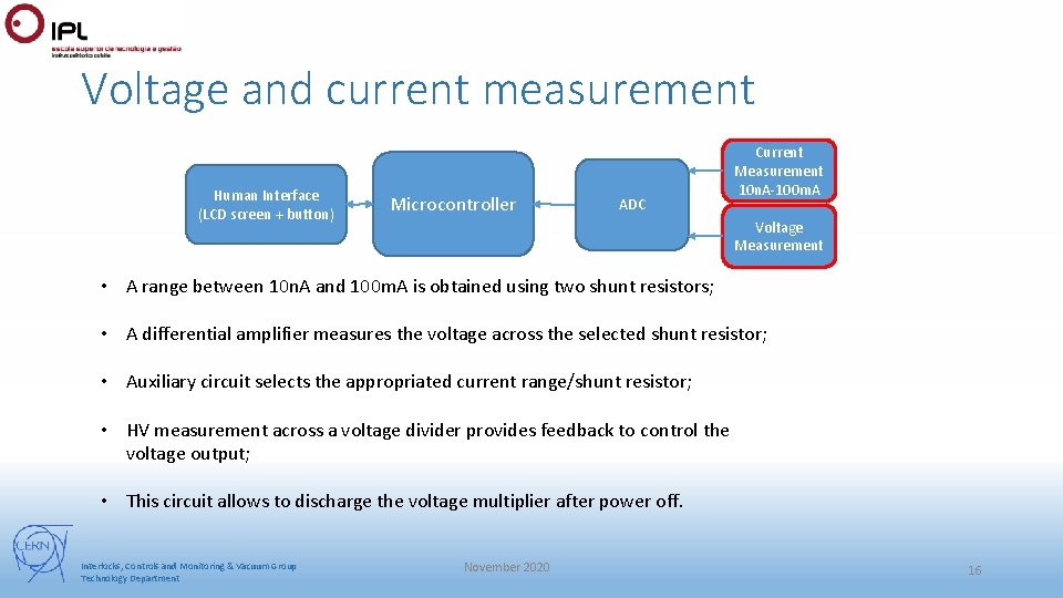
Voltage and current measurement Human Interface (LCD screen + button) Microcontroller ADC Current Measurement 10 n. A-100 m. A Voltage Measurement • A range between 10 n. A and 100 m. A is obtained using two shunt resistors; • A differential amplifier measures the voltage across the selected shunt resistor; • Auxiliary circuit selects the appropriated current range/shunt resistor; • HV measurement across a voltage divider provides feedback to control the voltage output; • This circuit allows to discharge the voltage multiplier after power off. Interlocks, Controls and Monitoring & Vacuum Group Technology Department November 2020 16
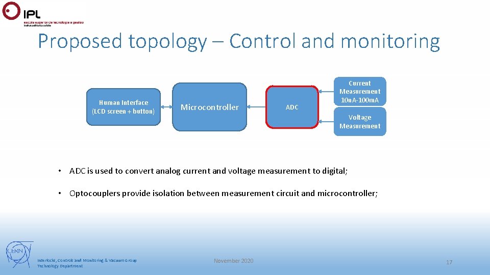
Proposed topology – Control and monitoring Human Interface (LCD screen + button) Microcontroller ADC Current Measurement 10 n. A-100 m. A Voltage Measurement • ADC is used to convert analog current and voltage measurement to digital; • Optocouplers provide isolation between measurement circuit and microcontroller; Interlocks, Controls and Monitoring & Vacuum Group Technology Department November 2020 17
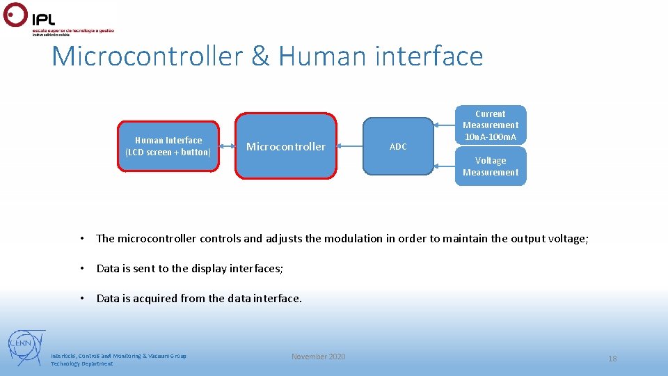
Microcontroller & Human interface Human Interface (LCD screen + button) Microcontroller ADC Current Measurement 10 n. A-100 m. A Voltage Measurement • The microcontroller controls and adjusts the modulation in order to maintain the output voltage; • Data is sent to the display interfaces; • Data is acquired from the data interface. Interlocks, Controls and Monitoring & Vacuum Group Technology Department November 2020 18
Conclusion Tests performed: • Each block was separately tested to make the trouble shooting easier; • For all the block was used a low voltage first (safety measures); • One of the final test reveal that the circuit is able to produce high voltage. One of the test revealed up to 9 k. V on the output. Problems: • Transistors can be turned on due to high d. V/dt – can be avoided by using filter; • IGBT protection circuit takes to long to response – create a new topologies; Future work: • Program and test the control and monitoring board; • Additional test that simulate a real environment; Interlocks, Controls and Monitoring & Vacuum Group Technology Department November 2020 19
Thank you for your attention Interlocks, Controls and Monitoring & Vacuum Group Technology Department November 2020 20