Single phase transformer Q 1 what is the


 Describe the operation of a single –phase transformer, explaining Clearly the functions")


 WHAT IS AN IDEAL TRANSFORMER? WHAT ARE THE PROPERTIES OF IDEAL TRANSFORMER?")
 A SINGLE –PHASE , 50 HZ TRANSFORMER HAS 80 TURNS ON THE")


 The no-load current of a transformer is 5 A at 0. 3")

 WHAT ARE THE EFFECT OF LEAKAGE FLUX IN TRANSFORMER Ans: - Due to")

 Find the active and reactive components of no-load current, and the no-load")


 Copper")


- Slides: 47
Single –phase transformer
Q. 1 what is the transformer? What is the differentiate between step. Up and step-down transformer? A transformer is an ac static device which transfers electric power From one circuit to anther without changing it frequency. When the transformer raises the voltage i. e. when the output voltage Of a transformer is higher than its input voltage, it is called the step. Up transformer. When the transformer output voltage is lower than input voltage , It is called the step-down transformer. 1
N 2>N 1 N 1>N 2 Step-down transformer
(Q. 2) Describe the operation of a single –phase transformer, explaining Clearly the functions of the different parts. Why are the cores Laminated?
Working : When an alternating voltage V 1 is applied to the primary, an alternating flux ø is set up in the core. This alternating flux links both the windings and induces , e. m. f s E 1 and E 2 in them according to faraday’s law of electro magnetic induction. The e. m. f E 1 is termed as primary e. m. f and e. m. f E 2 is termed as Secondary e. m. f. Clearly, E 1= -N 1 xdø/dt E 2= -N 2 x dø/dt
And , E 2/E 1=N 2/N 1 Note that magnitude of E 2 and E 1 depend upon the number Of turns of the secondary and primary respectively. If N 2>N 1, then E 2>E 1 (or V 2>V 1) and we get a step-up transformer. On the other end if N 2<N 1, then E 2<E 1 (or V 2<V 1) and we get a step-down transformer. If load is connected across the secondary winding , the secondary e. m. f E 2 will cause a current I 2 to flow through the load.
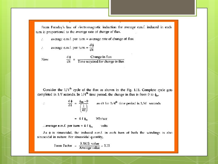
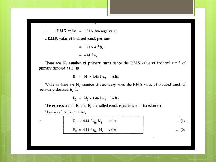
E. M. F EQUATION OF TRANSFORMER
(Q. 3) WHAT IS AN IDEAL TRANSFORMER? WHAT ARE THE PROPERTIES OF IDEAL TRANSFORMER? A transformer is said to be ideal if it satisfies following properties (i) It has no losses. (ii) Its winding have zero resistance (iii) Leakage flux is zero (iv) Permeability of core is so high that negligible current is required to establish the flux in it.
(Q. 4) A SINGLE –PHASE , 50 HZ TRANSFORMER HAS 80 TURNS ON THE PRIMARY WINDING AND 400 TURNS ON THE SECONDARY WINDING. THE NET CROSS-SECTIONAL AREA OF THE CORE IS 200 Cm^2. IF THE PRIMARY WINDING IS CONNECTED TO A 240 V, 50 HZ SUPPLY, DETERMINE. (i) The e. m. f induced in the secondary winding. (ii) The maximum value of the flux density in the core. Q. 5 For s single phase transformer having primary and secondary Turns of 440 and 880 respectively, determine the transformer KVA rating if half load secondary current is 7. 5 A and maximum value of Core flux is 2. 25 mwb.
IDEAL TRANSFORMER ON NO LOAD
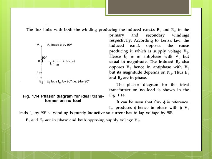
Phasor diagram for ideal transformer on no -load
IDEAL TRANSFORMER ON NO -LOAD
PRACTICAL TRANSFORMER ON NO LOAD The no-load equivalent circuit for the transformer
PHASOR DIAGRAM FOR PRACTICAL TRANSFORMER ON NO LOAD From the phasor diagram
Q. 4 Explain phasor of transformer on no-load? THEORY EXPLANATION PHASOR DIAGRAM OF TRANSFORMER AT NO LOAD A transformer is said to be on no-load when secondary winding Is open –circuited. The secondary current is thus zero. When an alternating voltage is applied to the primary, a small current flows in the primary. The current is called the no-load current of the transformer. It is made up of two components (i) A purely reactive component called magnetizing component of no load current which required to produce the flux. this is Called watt less component. (ii) An active component which supplies total losses under no-load condition called power component of no load current. This is also called watt ful component or core loss component of no. Load current.
LOSSES IN TRANSFORMER Core loss 1. Hysteresis loss 2. eddy current loss Copper loss
The flux Ø is taken as the reference phasor. since E 1 and E 2 are induced by the same flux , they will be in phase With each other. (Q. 3) A transformer takes 0. 8 A when its primary is connected to 200 V, 50 HZ supply. The secondary is open-circuited. The power absorbed from the supply is 60 watts. Determine the iron loss current and magnetising current. (Q. 4) A 2200/200 v transformer takes no load current of 0. 6 A and absorbs 400 watts. Find (i) magnetising current (iii) Iron-loss Current.
(Q. 3) The no-load current of a transformer is 5 A at 0. 3 power factor lagging when supplied at 230 V, 50 HZ. The number of turns on the primary winding is 200. Calculate (i) the maximum value of flux in the core. (ii) the core loss (iii) the magnetising current.
Leakage flux in transformer All the flux in transformer will not be able to link with both the primary and secondary windings. A Small portion of flux will link either winding but not both. This portion of flux is called Leakage flux. Both primary and secondary currents produce flux. The flux which Which links both the winding is the useful flux and is called mutual Flux.
(Q) WHAT ARE THE EFFECT OF LEAKAGE FLUX IN TRANSFORMER Ans: - Due to this leakage flux in transformer there will be a Self –reactance in the concern winding. This self-reactance of transformer is alternatively known as leakage reactance of transformer. Resistance of transformer Generally both primary and secondary windings of transformer are made of copper. These copper windings have own resistance.
IMPEDANCE OF TRANSFORMER As we said , both primary and secondary windings will have resistance and leakage reactance. These resistance and reactance will be in combination is nothing but impedance Of transformer. If R 1 and R 2 and X 1 and X 2 are primary & Secondary resistance and reactance of transformer respectively. So Z 1 and Z 2 impedance of primary and secondary Winding are respectively. Z 1=(R+JX 1) Z 2=(R+JX 2)
(Q. 4) Find the active and reactive components of no-load current, and the no-load current of a 440/220 v single-phase transformer if the Power input to the hv winding is 80 w. The low-voltage is kept open. The power factor of the no-load current is 0. 3 lagging. Input power = iron loss of the transformer
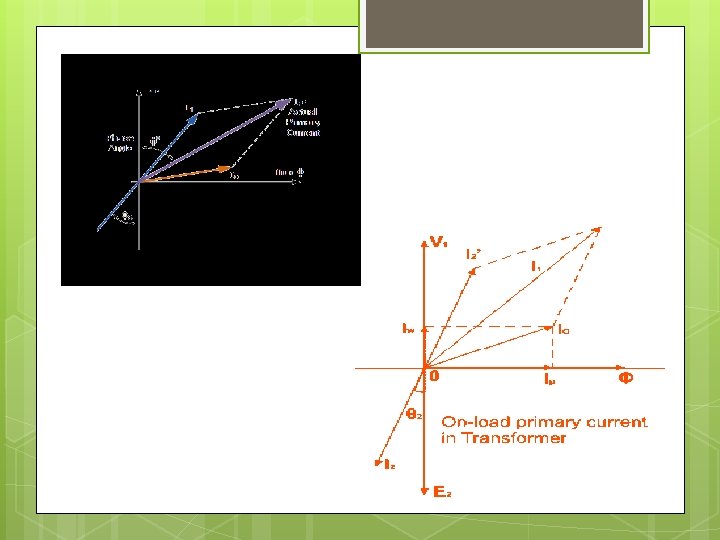
Practical transformer on load Assume that having no winding resistance and leakage reactance
Theory of transformer on load, with resistance as well as leakage reactance in transformer. For inductive load
Equivalent circuit of transformer
TRANSFORMER WITH RESISTANCE AND LEAKAGE REACTANCE
EQUIVALENT RESISTANCE When secondary resistance is transferred to the primary, it is divided by
Referred to primary Equivalent resistance of transformer referred to primary is
Referred to secondary When primary resistance is transferred to the secondary, it Is multiplied by
So equivalent resistance of transformer referred to the secondary is Similarly , when primary reactance is transferred to the secondary, It is multiplied by. It is then called equivalent primary reactance and is denoted by
SO EQUIVALENT REACTANCE OF TRANSFORMNER REFERRED TO SECONADRY IS
EQUIVALENT IMPEDANCE OF TRANSFORMER REFFERED TO SECONDARY IS
REFERRED TO PRIMARY When secondary resistance or reactance is transferred to the primary, It is divided by Equivalent resistance of transformer referred to primary is
EQUIVALENT RESISTANCE OF TRANSFORMER REFERRED TO PRIMATY IS Equivalent impedance of transformer referred to primary is
1. A 6600/400 V, single phase transformer has primary resistance of 2. 5Ω and secondary resistance of 0. 01Ω. Calculate total equivalent resistance referred to primary and Secondary. K=voltage transformation ratio. K=N 2/N 1=V 2/V 1=E 2/E 1 GIVEN Data are R 1=2. 5Ω, R 2=0. 01Ω
2. A 100 KVA transformer has 400 turns on the primary and 80 turns on the secondary. The primary and secondary resistance are 0. 3Ω and 0. 01Ω respectively and the corresponding leakage reactance are 1. 1Ω and 0. 035Ω respectively. Calculate the equivalent impedance referred to secondary circuit. Sol: -
ASSIGNMENT 1. A 10 KVA, 2000/400 V single-phase transformer has the following Resistance and leakage reactances. Primary winding : resistance 6Ω : leakage reactance 10 Ω Secondary winding: resistance 0. 8Ω : leakage reactance 0. 4Ω Calculate (i) equivalent resistance referred to secondary. (ii) equivalent leakage reactance referred to secondary.
2. A 15 k. VA, 2200/110 V transformer has R 1= 1. 75Ω, R 2=0. 0045Ω, the Leakage reactances are X 1=2. 6Ω and X 2=0. 0075Ω. calculate (a) Equivalent resistance referred to primary. (b) Equivalent resistance referred to secondary. (c) Equivalent reactance referred to primary. (d) Equivalent reactance referred to secondary. (e) Equivalent impedance referred to primary. (f) Equivalent impedance referred to secondary. (g) total copper loss
Open circuit test of transformer A voltmeter , wattmeter and an ammeter are connected in LV side Of the transformer as shown The HV side of the transformer is kept Open. Now with the help of varic applied Is slowly increase until the voltmeter gives reading equal to the rated voltage of the LV side. After reaching at rated LV side Voltage , all three instruments reading are recorded. The applied primary voltage V 1 is measured by the voltmeter, the No-load current by ammeter and no-load Input power by wattmeter as shown in fig. Hence watt-meter will record the iron losses and small copper losses In the primary.
Since no-load current is vary small (usually 2 -10 % of rated current) Copper losses in the primary under no-load condition are negligible as compared with iron losses. Hence , wattmeter reading practically gives the core losses in the Transformer.
Short –circuit test of transformer The connection diagram for short –circuit test on transformer is shown in figure. In this test , the secondary is short circuited by a thick conductor and variable low Voltage applied to the primary. There is no output from the transformer under short –circuit Conditions. therefore, input power is all losses and this loss is Almost entirely copper loss. it is because iron loss in the core Is negligibly small since the applied voltage is small.
Q-12 ADVANTAGESE OF TRANSFORMER TEST. Q. 13 EXPLAIN AUTO TRANSFORMER Auto transformer is kind of electrical transformer where primary and secondary shares same common single winding.