
PUMPS R Bhandari Senior Lecturer Lesson Overview Lesson
PUMPS R. Bhandari Senior Lecturer
Lesson Overview Lesson covers the type of pumps commonly installed on board ships, their constructions, working principles, characteristics, safety operation. 2/28/2021 2
Learning Objectives n n n n Definition of Pump Classification of Pumps Working principles of positive displacement pumps Construction features of positive displacement pumps Working principles of rotordynamic pumps Construction features of rotordynamic pumps Characteristics of pumps Safe operation of pumps 2/28/2021 3
Tutorial 1. State the classification of pumps used for shipboard application. 2. With the aid of a labelled sketch, briefly explain the working principle of a typical n i) reciprocating pump n ii) gear pump n iii) vane pump n Iv) centrifugal pump 2/28/2021 4
Tutorial 4. 5. 6. Draw the pump performance (H-Q) curve for the centrifugal pump Explain with NPSH how suction condition of the pump may be improved Explain the cause of efficiency drop in centrifugal pump. 2/28/2021 5
Tutorial 7. 8. Briefly explain the differences between positive displacement and rotodynamic pumps. With reference to the operation of a pump, explain the terms ‘self-priming’ and ‘non-self priming’. 2/28/2021 6
Definition Pump is a device that imparts energy to a fluid passing through it to enable the fluid to move from one point to another. In practice, pumps change both the velocity and the pressure passing through them. 2/28/2021 7
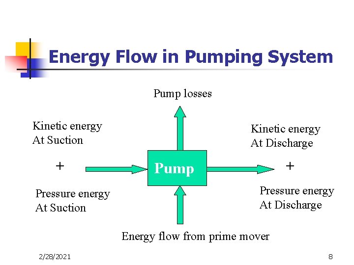
Energy Flow in Pumping System Pump losses Kinetic energy At Suction + Pressure energy At Suction Kinetic energy At Discharge + Pump Pressure energy At Discharge Energy flow from prime mover 2/28/2021 8
Types of Pumps Marine Pumps fall into two broad classes: n Positive Displacement Pumps n Roto-dynamic Pumps 2/28/2021 9
Positive Displacement Pumps Working Principles: n n n Fluid is displaced from the suction to the discharge by the mechanical variation of the volume of chamber or chambers at every stroke or rotation of the pump Volume of pump chamber alternately increases to draw the liquid in from suction pipe & then decreased to force the liquid out into the delivery pipe This may be done by either a reciprocating motion of a piston or by a rotary motion of specially designed vanes, gears or screws 2/28/2021 10
Positive Displacement Pumps Characteristic n n Self-priming All the valves at the discharge side of the pumps must be kept open prior starting Failure to do so will cause rapid increase of fluid pressure, leading to failure at the weakest point in the system Relief valve is always fitted in the system to avoid such failure 2/28/2021 11
Positive Displacement Pumps Subdivided into Two main categories: n Reciprocating Pumps - where plunger or piston is reciprocated in a fluid cylinder - suitable for delivering small quantities at high pressure n Rotary Pumps ( Gear, Screw, Vane pumps ) - where the liquid is forced through the pump casing by means of screws, gears or vanes - used for delivering moderate quantity at moderate pressure 2/28/2021 12
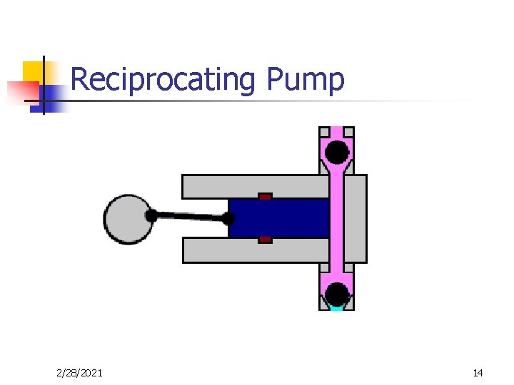
Reciprocating Pump Main Components n n n Cylinder Piston rod Gland Suction valve Discharge valve Pump may be of Single acting or Double acting type 2/28/2021 13
Reciprocating Pump 2/28/2021 14
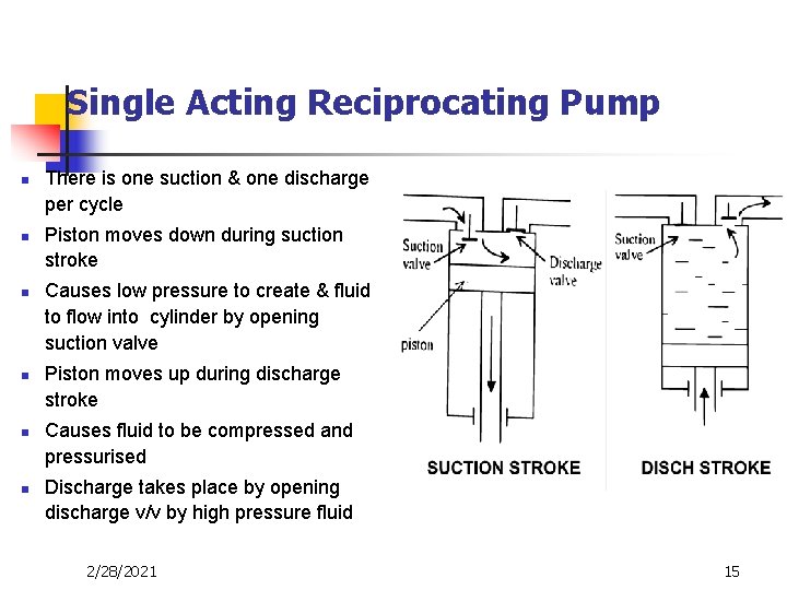
Single Acting Reciprocating Pump n n n There is one suction & one discharge per cycle Piston moves down during suction stroke Causes low pressure to create & fluid to flow into cylinder by opening suction valve Piston moves up during discharge stroke Causes fluid to be compressed and pressurised Discharge takes place by opening discharge v/v by high pressure fluid 2/28/2021 15

Double Acting Reciprocating Pump n n There is two suction & two discharge per cycle Piston moves from left to right (one stroke) Piston compresses fluid above piston (discharge) Piston draws fluid below piston (suction) 2/28/2021 16
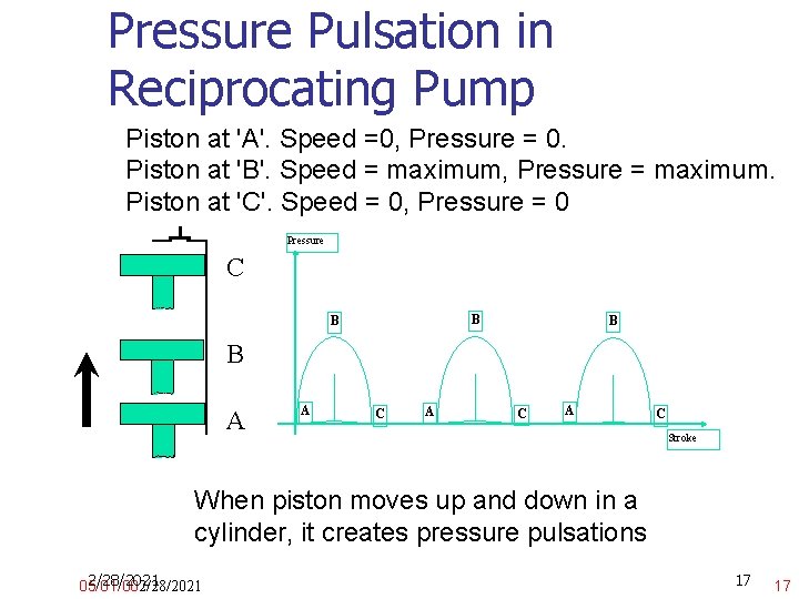
Pressure Pulsation in Reciprocating Pump Piston at 'A'. Speed =0, Pressure = 0. Piston at 'B'. Speed = maximum, Pressure = maximum. Piston at 'C'. Speed = 0, Pressure = 0 Pressure C B B A A C A C Stroke When piston moves up and down in a cylinder, it creates pressure pulsations 2/28/2021 05/01/002/28/2021 17 17
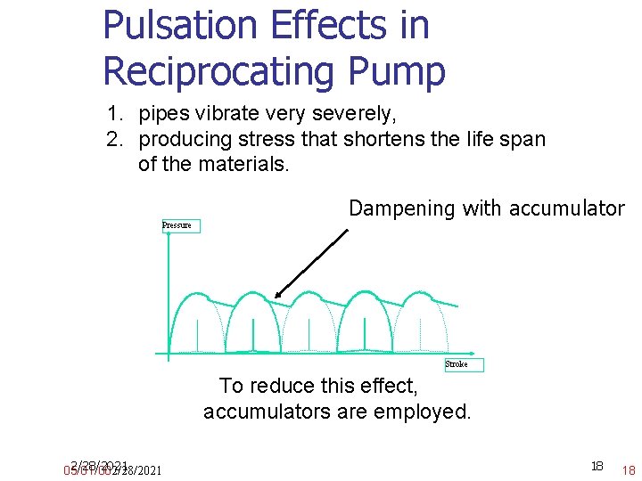
Pulsation Effects in Reciprocating Pump 1. pipes vibrate very severely, 2. producing stress that shortens the life span of the materials. Pressure Dampening with accumulator Stroke To reduce this effect, accumulators are employed. 2/28/2021 05/01/002/28/2021 18 18
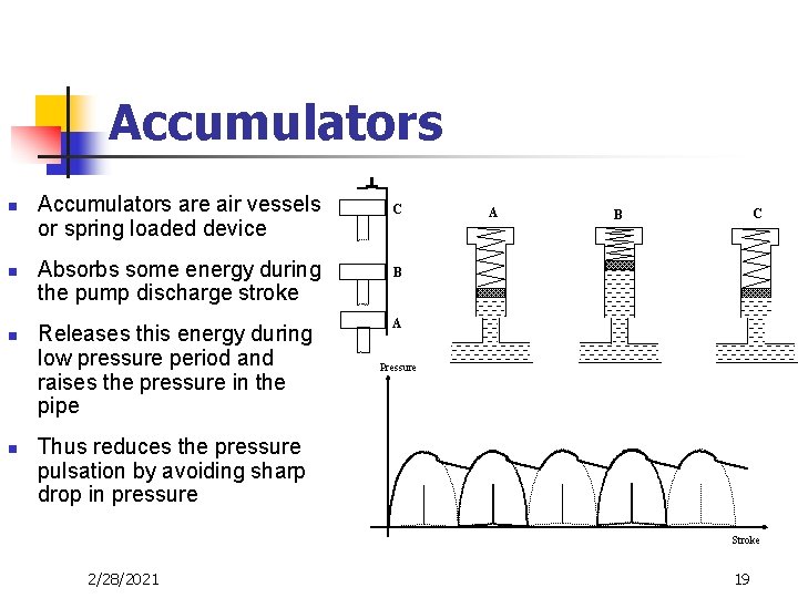
Accumulators n n Accumulators are air vessels or spring loaded device Absorbs some energy during the pump discharge stroke Releases this energy during low pressure period and raises the pressure in the pipe C A C B B A Pressure Thus reduces the pressure pulsation by avoiding sharp drop in pressure Stroke 2/28/2021 19
Gear Pump 2/28/2021 20
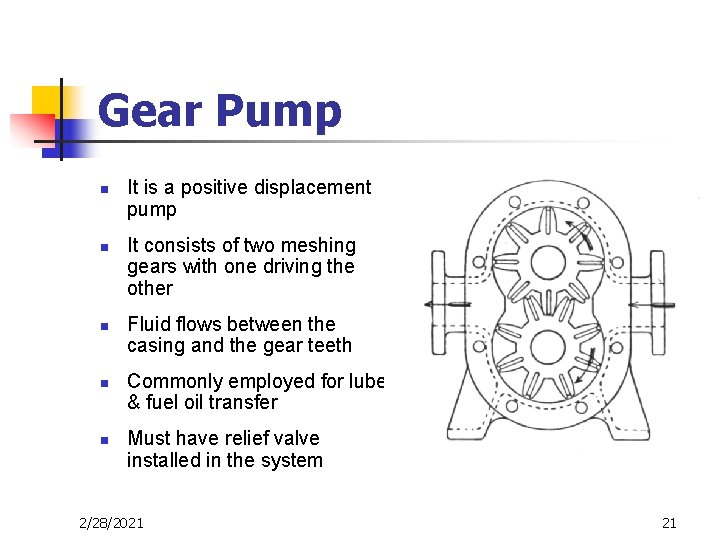
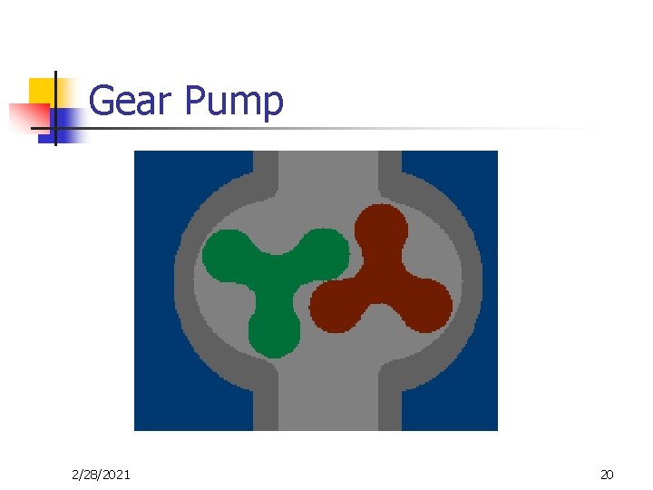
Gear Pump n n n It is a positive displacement pump It consists of two meshing gears with one driving the other Fluid flows between the casing and the gear teeth Commonly employed for lube & fuel oil transfer Must have relief valve installed in the system 2/28/2021 21

Screw Pump n n Screw pumps are positive displacement pumps Screws are meshed together with one driving other Fluid is displaced through the recesses between the screws and the casing May have single, double or triple screws 2/28/2021 22
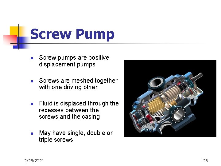
Screw Pump n n Screw pumps are positive displacement pumps Screws are meshed together with one driving other Fluid is displaced through the recesses between the screws and the casing May have single, double or triple screws 2/28/2021 23

Vane Pump n n n Vane pumps are positive displacement pumps Rotors having slots for vanes Centre of rotor is eccentric with casing This causes vanes to move in and out as the rotor rotates Causes change in volume in the respective chamber, similar to reciprocating pump 2/28/2021 24
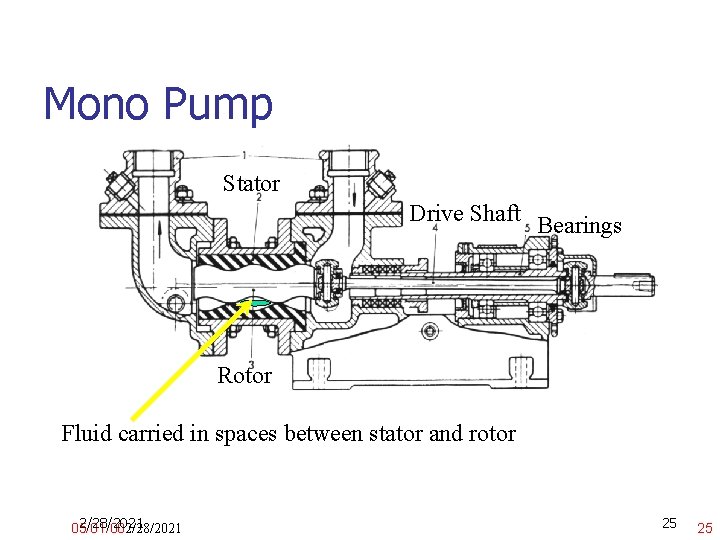
Mono Pump Stator Drive Shaft Bearings Rotor Fluid carried in spaces between stator and rotor 2/28/2021 05/01/002/28/2021 25 25
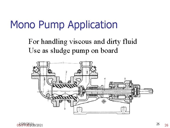
Mono Pump Application For handling viscous and dirty fluid Use as sludge pump on board 2/28/2021 05/01/002/28/2021 26 26
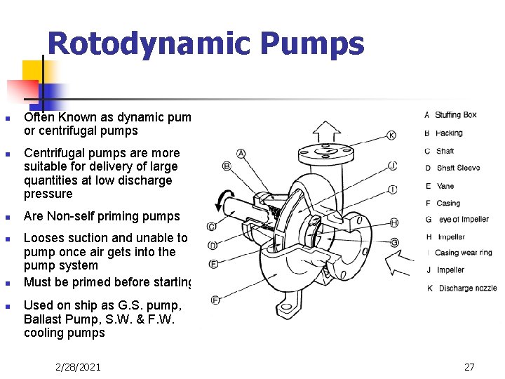
Rotodynamic Pumps n n n Often Known as dynamic pumps or centrifugal pumps Centrifugal pumps are more suitable for delivery of large quantities at low discharge pressure Are Non-self priming pumps Looses suction and unable to pump once air gets into the pump system Must be primed before starting Used on ship as G. S. pump, Ballast Pump, S. W. & F. W. cooling pumps 2/28/2021 27
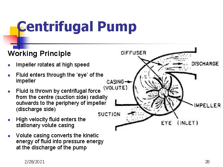
Centrifugal Pump Working Principle n n n Impeller rotates at high speed Fluid enters through the ‘eye’ of the impeller Fluid is thrown by centrifugal force from the centre (suction side) radially outwards to the periphery of impeller (discharge side) High velocity fluid enters the stationary volute casing Volute casing converts the kinetic energy of fluid into pressure energy at the discharge of the pump 2/28/2021 28
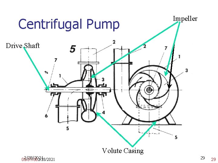
Centrifugal Pump Impeller Drive Shaft Volute Casing 2/28/2021 05/01/002/28/2021 29 29
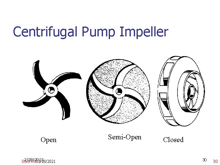
Centrifugal Pump Impeller Open 2/28/2021 05/01/002/28/2021 Semi-Open Closed 30 30
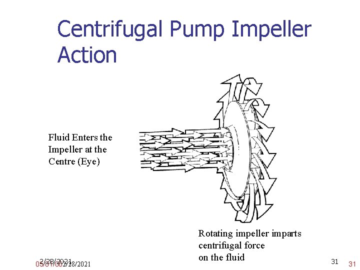
Centrifugal Pump Impeller Action Fluid Enters the Impeller at the Centre (Eye) 2/28/2021 05/01/002/28/2021 Rotating impeller imparts centrifugal force on the fluid 31 31
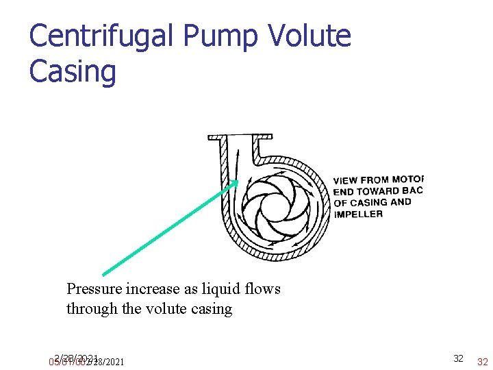
Centrifugal Pump Volute Casing Pressure increase as liquid flows through the volute casing 2/28/2021 05/01/002/28/2021 32 32
Centrifugal Pump Applications In all high volume and low pressure applications: 1. Cooling Water 2. Ballast Pump 3. Cargo Pump Multi Stage Pumps are used for higher pressure application 1. Fire Pumps 2. Boiler Water Feed Pumps 2/28/2021 05/01/002/28/2021 33 33
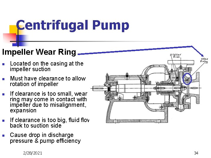
Centrifugal Pump Impeller Wear Ring n n n Located on the casing at the impeller suction Must have clearance to allow rotation of impeller If clearance is too small, wear ring may come in contact with impeller due to misalignment, expansion If clearance is too big, fluid flows back to suction side Cause drop in discharge pressure & pump efficiency 2/28/2021 34
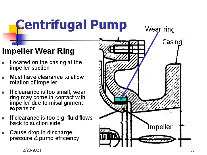
Centrifugal Pump Wear ring Casing Impeller Wear Ring n n n Located on the casing at the impeller suction Must have clearance to allow rotation of impeller If clearance is too small, wear ring may come in contact with impeller due to misalignment, expansion If clearance is too big, fluid flows back to suction side Cause drop in discharge pressure & pump efficiency 2/28/2021 Impeller 35
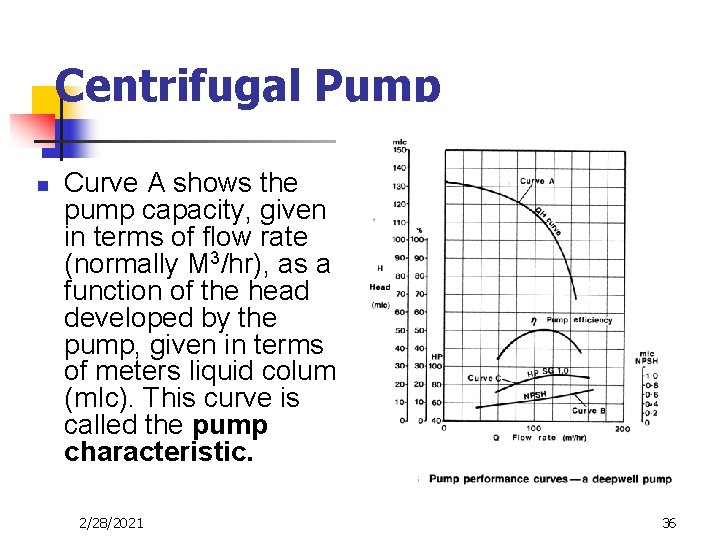
Centrifugal Pump n Curve A shows the pump capacity, given in terms of flow rate (normally M 3/hr), as a function of the head developed by the pump, given in terms of meters liquid column (m. Ic). This curve is called the pump characteristic. 2/28/2021 36
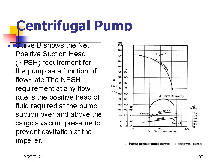
Centrifugal Pump n Curve B shows the Net Positive Suction Head (NPSH) requirement for the pump as a function of flow‑rate. The NPSH requirement at any flow rate is the positive head of fluid required at the pump suction over and above the cargo's vapour pressure to prevent cavitation at the impeller. 2/28/2021 37
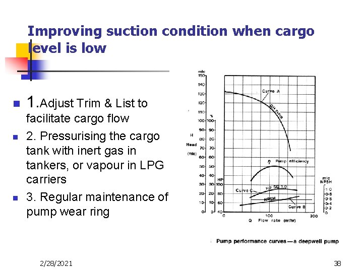
Improving suction condition when cargo level is low n n n 1. Adjust Trim & List to facilitate cargo flow 2. Pressurising the cargo tank with inert gas in tankers, or vapour in LPG carriers 3. Regular maintenance of pump wear ring 2/28/2021 38
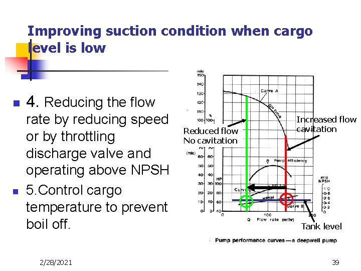
Improving suction condition when cargo level is low n n 4. Reducing the flow rate by reducing speed or by throttling discharge valve and operating above NPSH 5. Control cargo temperature to prevent boil off. 2/28/2021 Reduced flow No cavitation Increased flow cavitation Tank level 39
- Slides: 39