Pneumatic Balancers Balancer Advanced Objectives Balancer Operation Balancer

Pneumatic Balancers Balancer Advanced

Objectives · Balancer Operation · Balancer Maintenance · Control Function · Control Adjustment & Installation

Summary • The Balancer has smooth operation, variable capacity, multiple control choices, multiple mounting options and minimal air consumption. • Understanding the operation and function of the balancer and various controls is an important factor in the proper use of the balancer system.

Module Preview • If a balancer with ZA controls allows a load to drift to the floor in less than a minute what is the cause? • When facing the end cover which direction does the reel rotate? • If air pressure is released from the piston chamber the load will ______. • Which control is best suited for a lifting application?

WIRE ROPE CONTROLS TRAVEL CAPACITY SUSPENSION Z-STOP

10 inch diameter 200, 350 & 500 lb. Capacity 6. 5 inch diameter 150 lb. Capacity

Operating Capacity • Determined by Air Pressure – “Plant Operating” Pressure • Rated Capacity @ 100 psi

Operating Capacities • Air Pressure ÷ 100 = Capacity Factor 50 psi ÷ 100 =. 50 Factor • Capacity Factor x Rated Capacity= Operating Capacity. 50 x 350 = 175 lb.


Reeved & Tandem

Travel • Total Rope > Reel Capacity • Travel = High Point - Low Point • Reeved Travel = 1/2 Straight Travel


Balancer Function

Z-Brake Reel Thrust Bearing Piston End Cover End Cap Ball Screw and Nut Housing

Main Air Supply Control Body

Main Air Supply

Main Air Supply

Main Air Supply

Main Air Supply

Main Air Supply

Balancer Preventive Maintenance • Clean and lubricate piston, ball screw and ball nut annually • Refer to Balancer Service Manual form MHD 56151

Z-Brake • Safety Retraction System • Centrifugal Force • Prevents Excessive Upward Acceleration • Standard On All Units Except 50 lb. Tool Balancer • Patent No. 5, 522, 581

Brake Shoe Engagement Brake Engagement Direction Spring Tension Adjustment

If the brake engages repeatedly during normal operation it will damage the balancer

Z-Brake Preventive Maintenance • Required annually • Check for engagement • Check condition

Wire Rope • 1400 lb. Working Capacity • 250, 000 Cycles

Wire Rope Inspection • Perform daily • Use a glove • Check entire length • Replace when frayed


Of the wire rope occur with normal wear

Load Hooks Crosby/ Bullard Golden Gate® Lift Lok ® Working limit 1/2 ton Ultimate load= 2 tons

Top bail swivels Load Hook Inspection Quic-Check® align @ 1 -1/2 inch Self Closing Gate Tip of hook aligns

Z-Stop- Option Engagement Plate Engagement Pin Housing

How a Z-Stop Works: Main Air Supply Piston Pressure Patent No. 5, 522, 581 & 5, 848, 781

How a Z-Stop Works: Main Air Supply Piston Pressure BALANCER 65 60 PSI Engagement Plate Main Piston

How a Z-Stop Works: When Main Air Supply Pressure Falls Below Piston Pressure The Pin Shifts and Engages the Plate, locking out the rotation of the reel. Main Air Supply Piston Pressure BALANCER 60 55 Engagement Plate PSI Main Piston

How a Z-Stop Works: Main Air Supply Piston Pressure BALANCER 65 60 PSI Engagement Plate Main Piston

Z-Stop Housing End Cover Z-Stop Inspection Check engagement Check leakage


• ZA- ZIM AIR • BA- BALANCE AIR • EA- EQUALIZED AIR
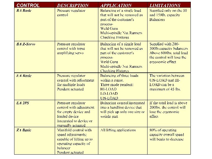

ZA- Pendent Control • “Hoisting” Applications • Ergonomic Pendant • Adjustable Speed • Smooth Shock Free Lifting

ZA PENDENT • Operates like an accelerator • Versatile speed control • Lightweight aluminum construction

How a ZA Control Works: Main Air Supply

How a ZA Control Works: Main Air Supply Air Suppl y Supply air is trapped at the Up lever

How a ZA Control Works: Main Air Supply When the UP lever is depressed The air flows past the Down lever valve up the hose Raising the load

How a ZA Control Works: Main Air Supply The load is in balance and pressure traps at the down lever valve when the controls are inactive

How a ZA Control Works: Main Air Supply To lower the load the depress the Down lever Pressure escapes to atmosphere through the pendent

• Normal Setting Flush to Top • Compensates for leakage Hook Balance Adjustment

Down Speed Control ZA MANIFOLD Up Speed Control Air Supply Inlet

BA- Balance Control • 50 lb. and 150 lb. Balancers • BA Control • Versatility • Virtually Maintenance Free • 60 and 80 inch Travel
 Nut Adjustment Lock Nut")
Check valve Exhaust Ports Adjustment (Acorn) Nut Adjustment Lock Nut

EA Balance Controls BA Z-Servo EA 2 PS Control EA Basic

EA Regulator Inlet Port “B” Port
 Nut")
Main Regulator Exhaust Port Control Regulator Adjustment (Acorn) Nut

Check Valve Trim Valve Auxiliary Flow Valve “A” Port

BA Z-Servo Control • 200, 350 & 500 lb. Balancers • Amplifies Operator Input • 3% - 5% of Load • Ideal For: • Tool Balancing • Weld Gun Suspension • Fixture Suspension

Air Supply “A” Port EA Regulator Control Tube Vent Z-Servo Valve

Knurl Nut Z-Servo Valve Servo Body Servo Spring

A B • At all times air vents at the Z-Servo to balance the load when not being manipulated. Air venting to balance load

A B • When the load lowers the spring pushes against the ZServo valve, venting air to atmosphere until the EA regulator begins to exhaust air to lower the load. Air vent increases to lower load

A B • When the load moves up; vented at the Z-Servo valve reduces, sending a signal back to the EA regulator to increase pressure to the balancer to lift. Air vent decreases to lower load

• The knurl nut at the top of the servo provides fine tuning adjustment of the control. Knurl Nut
 Control EA Basic Control • Balances 3 Different Weights • Maximum 40")
EA (Equi-Air) Control EA Basic Control • Balances 3 Different Weights • Maximum 40 lb. Variation • 3 Position Pendant Control • Hi Load • Low Load • No Load

A B In the HI-LOAD position, the EA regulator setting balances the heaviest load. No air vents at the handle. UNLOAD HILOAD LOLOAD

A B Pressure vents to atmosphere to balance lighter loads. HILOAD LOLOAD

A B Pressure vents to atmosphere to balance lighter loads. UNLOAD HILOAD

EA-2 PS Control • Integrated with Handling Device • Above Knees, Below Shoulders • Automatic Clamp & Balance • Empty Handling Device Balanced

A 14 5 Signal from part present switch 4 2 1 B 12 3 Set to balance loaded handling device Plugged port

A 14 4 5 No signal from part present switch B 2 12 1 3 Air release balances empty device Set to balance empty handling device

Interlock Prevents accidental release of a load while suspended Pressure from piston chamber shifts valve when a load is attached

Interlock Normal Condition Handling Device without load Balancer piston pressure Interlocked supply to Clamp cylinder or Vacuum generators disabled Supply to Clamp/ Vacuum Buttons 14 4 5 1 Handling device 2 12 3 air supply

Interlocked Condition Handling Device with load Balancer piston pressure increases shifting valve Interlocked supply to Clamp cylinder or Vacuum generators Supply to Clamp/ Vacuum Buttons disabled 14 4 5 1 Handling device 2 12 3 air supply

Suspension Kits • Enclosed Track • I-Beam • Hook Mount

Enclosed Track • Delrin wheels with life lubed bearings • All cast Aluminum trolley body

I-Beam • Adjustable from 2. 00 to 4. 00 inch running flange • Special kits can be purchased for wider flange widths

Hook Mount • Hook Installs closest to cable guide • Provided with Safety Cable

- Slides: 78