Taiwan Uni Grid YehChing Chung Department of Computer


 • The purpose of grid computing is to integrate various resources within")
 • All institutes that participate in the Uni. Grid project contribute some")
 • System Architecture")


 • Uni. Grid users can examine the status of system")
 • Screenshot of the system status monitoring web page")
 • Single sign-on is a mechanism whereby a single authentication can")
 • User identity verification through single sign-on service")
 • A Uni. Grid user can design and save his")
 • Structure of a workflow Workflow sequential execution parallel execution")
 • The workflows of each user is stored in the")
 • Screenshot of the workflow editing web page")
 • When an user submits a workflow, the portal will")
")
 • Users can examine the execution status of his workflow")
 • Screenshot of the workflow monitoring web page")
 • Screenshot of the Uni. Grid workflow management web page")

 • The broker provides a uniform interface to access available")
 • Broker workflow")
 • Each participating organization has a local scheduler (Condor) installed")
 • Tools have been developed to simulate different load sharing and")
 • Queuing methods (cont’d. ) – Single queue • Multi-pool centralized")
 • Scheduling policies – Non-FCFS • Multi-pool centralized queue • Single-pool")
 • Implementation Approaches – Multi-Pool Centralized Queue • Global queue scheduling")
 – Two-Level Scheduling (Empty-Queue-Only Multi-Pool Grid) • Global queue in the")
 • Simulation results Load sharing methods Average waiting time(sec. ) Standard")
 • Simulation results (cont’d. ) One big cluster 50. 36 774.")
 • Discussion – Non-FCFS methods can effectively improve the overall system")


 • Provides an interface for other services to query various information")
 • The Network Weather Service (NWS) – A distributed system that")
")
 • Screenshot of the node status webpage")
 • Input: any application (depending on the availability")
 • Execution of a Parallel Application using 4")
 • Communication localization & data partitioning techniques in cluster-based grid system")
 • Communication localization techniques for identical cluster Original communication patterns Localized")
 • Communication localization techniques for nonidentical cluster Original communication table")
 • Communication localization techniques for nonidentical cluster (cont’d. ) Localized communication")


 • Virtual storage system architecture")
 • The virtual storage system is implemented with Java as")
")
 • Screenshot of the storage service client program")
 • The Data Management is the Web-based Replica Access and Management")
 • Replica Location Service")
 • The Registration System – In Security • We design a")
 • The Search System – Replica Index and Replica Location •")
 • The Manager System – We plan to design a friendly")


- Slides: 65
Taiwan Uni. Grid Yeh-Ching Chung Department of Computer Science National Tsing Hua University Hsin-Chu, 300, Taiwan
Outline • • Introduction Portal Broker and Scheduler Resource Information Service Storage Service Applications Conclusion
Introduction (1) • The purpose of grid computing is to integrate various resources within a large network environment. • The purpose of the Uni. Grid project is to build a platform for academic research using grid-related technologies in Taiwan.
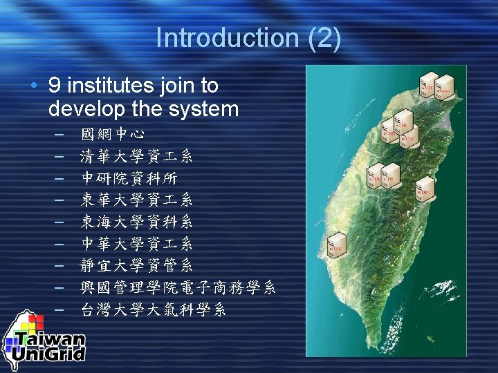
Introduction (3) • All institutes that participate in the Uni. Grid project contribute some resources. • These resources can be used in collaboration for large scale applications.
Introduction (4) • System Architecture
Outline • • Introduction Portal Broker and Scheduler Resource Information Service Storage Service Applications Conclusion
Portal • The Uni. Grid portal provides an interface for Uni. Grid users to use the resources available in the Uni. Grid system. • Functionalities of the portal – System status monitoring – Single sign-on – User workflow management – Project information
System Status Monitoring (1) • Uni. Grid users can examine the status of system resources through the portal. • The portal gathers the current system information from the information service and present these information to the users.
System Status Monitoring (2) • Screenshot of the system status monitoring web page
Single Sign-On (1) • Single sign-on is a mechanism whereby a single authentication can permit a user to access all resources where he has access permission, without the need to enter multiple passwords. – All user account information are kept in a database at the portal site. – When a user requests a service, his verification data is passed to that service. – The request will be granted only if the identity is verified by the verification web service
Single Sign-On (2) • User identity verification through single sign-on service
User Workflow Management (1) • A Uni. Grid user can design and save his own workflows at the Uni. Grid portal. • A user can select any workflow he designed and execute the workflow through the Uni. Grid portal. • A user can also monitor the status of his workflow through the Uni. Grid portal.
User Workflow Management (2) • Structure of a workflow Workflow sequential execution parallel execution
User Workflow Management (3) • The workflows of each user is stored in the portal storage in XML format. • <flow name="testflow" numstages="3"> <stage name="stage 1" numjobs="1"> <job id="0"> <sortkey>1</sortkey> <runtype>mpi</runtype> <workdir>/home/test/</workdir> <filename>mm_mpi</filename> <runrp>true</runrp> <datafile/> <argu>256</argu> <otherurl/> <cpuno>4</cpuno> </job> </stage> … </flow>
User Workflow Management (4) • Screenshot of the workflow editing web page
User Workflow Management (5) • When an user submits a workflow, the portal will pass the selected workflow information to the broker. • Upon receiving an execution request, the resource broker will find the required resource for that workflow and schedule its execution.
User Workflow Management (6)
User Workflow Management (7) • Users can examine the execution status of his workflow through the portal’s workflow monitoring system. • All workflow execution information are stored in a database at the machine with resource broker installed on it. • The portal queries the database and obtain the current status of a particular workflow. • The status information is processed and presented in the form of web pages.
User Workflow Management (8) • Screenshot of the workflow monitoring web page
User Workflow Management (9) • Screenshot of the Uni. Grid workflow management web page
Outline • • Introduction Portal Broker and Scheduler Resource Information Service Storage Service Applications Conclusion
Broker & Scheduler (1) • The broker provides a uniform interface to access available resources in the Uni. Grid system. • The broker uses the resource information service to obtain the current status of the resources in the system. • After these information are gathered, the broker will allocate the resources that meets the requirements of the current job. • The jobs are then passed to the corresponding local schedulers to be executed locally.
Broker & Scheduler (2) • Broker workflow
Broker & Scheduler (3) • Each participating organization has a local scheduler (Condor) installed to schedule the jobs assigned to that organization. • Condor – A scheduler for large collections of distributively owned computing resources – Developed by the researchers at University of Wisconsin – Specialized for compute-intensive jobs – Uses the “Class. Ad” mechanism to match job requirements to machine status and schedule the jobs according to the matching results
Related Research (1) • Tools have been developed to simulate different load sharing and scheduling policies on computing grid analyze their performance • Queuing methods – Independent clusters – Multiple queues • Forwarding to no-need-to-wait site • Forwarding to shortest-queue site • Forwarding to least-load site, load=
Related Research (2) • Queuing methods (cont’d. ) – Single queue • Multi-pool centralized queue • Single-pool centralized queue – One big cluster – Two-level scheduling • Empty queue only • Shortest queue first • Least load first – Two-level local queues • Forwarding to shortest-queue site
Related Research (3) • Scheduling policies – Non-FCFS • Multi-pool centralized queue • Single-pool centralized queue – FCFS • Two-level scheduling • The performance of Non-FCFS is three times better than FCFS
Related Research (4) • Implementation Approaches – Multi-Pool Centralized Queue • Global queue scheduling in the broker, no local queuing system • Global queue scheduling in the broker, making sure available processors through local queuing system – Single-Pool Centralized Queue • Global queue scheduling in the broker, no local queuing system
Related Research (5) – Two-Level Scheduling (Empty-Queue-Only Multi-Pool Grid) • Global queue in the broker, local queues in the local queuing systems
Related Research (6) • Simulation results Load sharing methods Average waiting time(sec. ) Standard deviation Average waiting ratio Standard deviation 2772. 63 10797. 80 21. 46 148. 07 Forwarding to no-need-to-wait site 111. 08 1658. 17 0. 51 8. 76 Forwarding to shortest-queue site 91. 80 1560. 22 0. 41 15. 59 Forwarding to least-load site 86. 28 1477. 90 0. 30 9. 32 127. 64 1487. 69 1. 03 20. 53 Single-pool centralized queue (slowdown ratio: 6) 2184. 36 17251. 00 23. 84 273. 75 Single-pool centralized queue (slowdown ratio: 5) 200. 71 2845. 86 1. 88 37. 81 Single-pool centralized queue (slowdown ratio: 4) 117. 57 1749. 76 0. 90 19. 42 Single-pool centralized queue (slowdown ratio: 2) 61. 71 946. 55 0. 47 13. 88 Single-pool centralized queue (no slowdown) 50. 36 774. 95 0. 37 11. 00 Independent clusters Local queue based methods Centralized queue based methods Multi-pool centralized queue
Related Research (7) • Simulation results (cont’d. ) One big cluster 50. 36 774. 95 0. 37 11. 00 Empty-queue-only multi-pool grid 67. 86 1239. 00 0. 22 6. 34 Shortest-queue-first multipool grid 75. 23 1361. 69 0. 23 5. 14 Least-load-first multi-pool grid 73. 22 1331. 80 0. 28 8. 50 94. 51 1764. 42 0. 34 10. 47 Two-level scheduling Methods with two local queues Forwarding to shortestqueue site
Related Research (8) • Discussion – Non-FCFS methods can effectively improve the overall system utilization and performance. – The smallest first non-FCFS policy outperforms all other policies in terms of waiting time and waiting ratio. – As the worst case is concerned, the backfilling policy is superior because it does not allow jobs to be delayed by the backfilling activities
Outline • • Introduction Portal Broker & Scheduler Resource Information Service Storage Service Applications Conclusion
Resource Information Services • The resource information service provides information about current resource status, these information can be used by other services of the system • Functionalities of the resource information service – Information system – Performance visualization of MPI parallel program’s execution
Information System (1) • Provides an interface for other services to query various information about computing nodes – The statistics about the individual nodes are obtained using MDS (Monitoring & Discovery Service) provided by the Globus Toolkit – The current network status between machines are gathered using NWS (Network Weather Service) • Automatic update of node information – When a new computing nodes is added/removed
Information System (2) • The Network Weather Service (NWS) – A distributed system that periodically monitors and dynamically forecasts the performance various network and computational resources can deliver over a given time interval – Developed by the researchers at UCSB – It uses numerical models to generate forecasts of what the conditions will be for a given time frame – Because this functionality is analogous to weather forecasting, the system is called Network Weather Service
Information System (3)
Information System (4) • Screenshot of the node status webpage
Performance Visualization of MPI Programs (1) • Input: any application (depending on the availability of compiler in grid platform) • Output: performance visualization of the execution of this application
Performance Visualization of MPI Programs (2) • Execution of a Parallel Application using 4 computing nodes
Related Research (1) • Communication localization & data partitioning techniques in cluster-based grid system – Localized communication enhances performance of parallel applications on grid – Adaptive data partitioning for identical cluster & non-identical cluster grid topology – In-core & out-of-core applications
Related Research (2) • Communication localization techniques for identical cluster Original communication patterns Localized communication patterns
Related Research (3) • Communication localization techniques for nonidentical cluster Original communication table
Related Research (4) • Communication localization techniques for nonidentical cluster (cont’d. ) Localized communication table
Outline • • Introduction Portal Broker and Scheduler Resource Information Service Storage Service Applications Conclusion
Storage Service • The goal of storage service is to provide a collaborative space where Uni. Grid users can share their data and resources with others. • Components of the storage service – Virtual storage system – Data management system
Virtual Storage System (1) • Virtual storage system architecture
Virtual Storage System (2) • The virtual storage system is implemented with Java as a web service • Uni. Grid services access the virtual storage system when they need to fetch/modify users’ data files • A client program is available for users to manage his own storage space • The files are stored in a master file server and replicas of the files are distributed to other machines
Virtual Storage System (3)
Virtual Storage System (4) • Screenshot of the storage service client program
Data Management (1) • The Data Management is the Web-based Replica Access and Management System • It consists of the Registration, Search and Manager system – The registration system is used in managing the user for accessing the Uni. Grid System – The search system combines with the RLS and Web technique – The manager system offers a friendly interface for manager, it will be easy to maintain the contents of database • Structure of the Data Management System
Data Management (2) • Replica Location Service
Data Management (3) • The Registration System – In Security • We design a web registration system • User need to be registered in portal and logged in by CA (Proxyinit) – In account manage • Administrator • User • The detailed structure of Web Service System
Data Management (4) • The Search System – Replica Index and Replica Location • In LRC Sever, we can execute the basic command. • We can update information of LRI server use the batch command – Services • We offer the service of the Job submit, files list, files upload and data replication in single server • The detailed structure of Web Service System
Data Management (5) • The Manager System – We plan to design a friendly interface for manager, it will be easy to maintain the contents of Metadatabase, update the RLS database and manage user’s account • The detailed structure of Web Service System
Outline • • Introduction Portal Broker and Scheduler Resource Information Service Storage Service Applications Conclusion
Applications 1 Simulations of atmospheric circulations with the NTU/Purdue nonhydrostatic numerical model. Model characteristics: Nonhydrostatic Explicit forward-backward integration for both high-frequency waves and gravity waves Implicit diffusion scheme with a TKE prognostic equation Time split schemes for high-frequency waves, gravity waves, diffusion, and surface processes. Physical processes: Cloud microphysics Surface similarity equation 3 -layer soil model Coriolis force
Performance with the Uni. Grid 2 Dimension Machine name NCHC-unigrid Ntu-Cluster Physical time 5 hr Running time 12 hr 17 min 12 hr 35 min 3 Dimension Physical time Running time 50 sec 30 min 50 sec 31 min
Commands for submitting jobs host #NTU uninode 11 2 uninode 12 2 uninode 14 2 uninode 15 2 host 1 uninode 11 uninode 10 uninode 12 uninode 14 uninode 15 uninode 7 uninode 9 /opt/mpich/pgi/bin/mpirun –nolocal –machinefile host –np 8 nonh 3 d. exe > test & makefile OBJ = nonh 3 d. o tograds. o copy. o update. o sound. o adv. o cloud 1. o dampini. o initial. o restart. o nbr 2 d. o startend. o tkeeq. o updtrp. o sprogi 4. o sprogi 2. o diffxy. o diffz. o pbl. o EXE =. . /nonh 3 d. exe OPT = -O 3 -Mextend -Msave -Bstatic -byteswapio #OPT = -O 3 -static -ffixed-line-length-80 #OPT = -O 3 -static #OPT = -O 3 #OPT = -static $(EXE) : $(OBJ) /opt/mpich/pgi/bin/mpif 77 $(OPT) -o $(EXE) $(OBJ). f. o : /opt/mpich/pgi/bin/mpif 77 $(OPT) -c $< clean: rm -f *. o. . /nonh 3 d. exe
Three-dimension simulation of a thermal bubble in an isentropic environment Initial spherical bubble develops into a mushroom-like shape. Two isentropic surfaces are shown. The isentropic surface corresponding to a higher potential temperature is in pink.
Two-dimensional simulation of a sea breeze 10 z 5 km 0 0 SBF 15 km x 30 The figure shows the total water mixing ratio (vapor plus liquid) over land after 2. 5 hr. The label under the x-axis is the distance from the coastline. Water vapor is pumped up from the ground surface in the convective boundary layer (with the red/orange color representing high water vapor content in the air). The location of the sea breeze front (SBF) is shown.
Applications 2 • FASTA – Compares a protein sequence to another protein sequence or to a protein database, or a DNA sequence to another DNA sequence or a DNA library
Applications 3 • Clustal. W – A general purpose multiple sequence alignment program for DNA or proteins.
Conclusions and Future Work • A prototype of Uni. Grid system has been developed • Enhance the data grid part of Uni. Grid • Promote the Uni. Grid system to universities in Taiwan