Strategic Standardisation Group Standards Radar Chart V 1
- Slides: 63
Strategic Standardisation Group Standards Radar Chart V 1. 10 7/12/2018 Copyright © 2018 Aero. Space and Defence Industries Association of Europe - ASD (based upon AIA presentation principle)
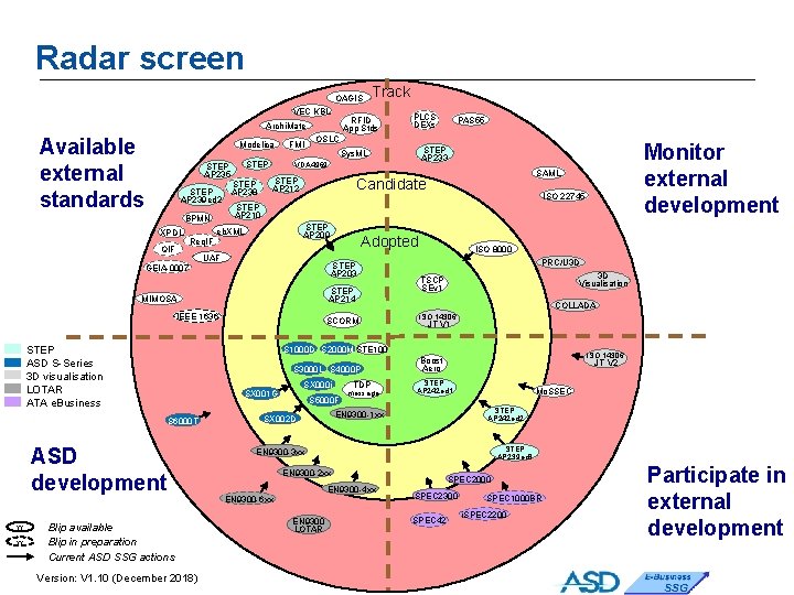
Executive Summary • The SSG Radar Chart shows the various technology standards under the attention of the SSG. • The Adopt Existing Standard quadrant refers to standards which have been developed outside of ASD but which have relevance to the ASD. • The Monitor External Development quadrant refers to standards which are being developed outside of the ASD but which may have relevance to the ASD. • The Participate in External Development quadrant refers to outside standards development where SSG members are actively participating and influencing. • The ASD Development quadrant shows standards and templates that the SSG is developing internally • Through this synthesis view, the SSG intends to build on the methods developed by AIA and to develop a common Aerospace view on e-Business Standards. Page 2/59
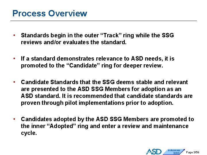
Process Overview • Standards begin in the outer “Track” ring while the SSG reviews and/or evaluates the standard. • If a standard demonstrates relevance to ASD needs, it is promoted to the “Candidate” ring for deeper review. • Candidate Standards that the SSG deems stable and relevant are presented to the ASD SSG Members for adoption as an ASD standard. It is recommended that candidate standards are proven through pilot implementations prior to adoption. • Candidates adopted by the ASD SSG Members are promoted to the inner “Adopted” ring and enter a review and maintenance cycle. Page 3/59
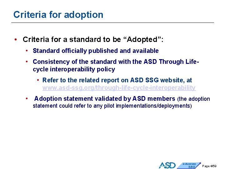
Criteria for adoption • Criteria for a standard to be “Adopted”: • Standard officially published and available • Consistency of the standard with the ASD Through Lifecycle interoperability policy • Refer to the related report on ASD SSG website, at www. asd-ssg. org/through-life-cycle-interoperability • Adoption statement validated by ASD members (the adoption statement could refer to any pilot implementations/deployments) Page 4/59
Radar screen OAGIS VEC KBL RFID App Stds Archi. Mate Available external standards Modelica STEP AP 235 STEP AP 239 ed 2 BPMN XPDL QIF STEP AP 238 yy UAF STEP AP 203 STEP AP 214 ISO 8000 PRC/U 3 D 3 D Visualisation TSCP SEv 1 • Supplier JT V 1 d UID • S 1000 D S 2000 M STE 100 SCORM SX 000 i SX 001 G Version: V 1. 10 (December 2018) ISO 22745 Adopted S 3000 L S 4000 P Blip available Blip in preparation Current ASD SSG actions SAML Candidate STEP AP 209 IEEE 1636 ASD development Monitor external development STEP AP 233 Sys. ML STEP AP 210 MIMOSA S 6000 T PAS 55 OSLC STEP AP 212 eb. XML STEP ASD S-Series 3 D visualisation LOTAR ATA e. Business PLCS DEXs VDA 4969 Req. IF GEIA-0007 yy FMI Track TDP S 5000 F message ISO 14306 Boost Aero JT V 2 STEP AP 242 ed 1 Mo. SSEC STEP AP 242 ed 2 EN 9300 -1 xx SX 002 D COLLADA ISO 14306 STEP AP 239 ed 3 EN 9300 -3 xx EN 9300 -2 xx EN 9300 -4 xx EN 9300 -6 xx EN 9300 LOTAR SPEC 2000 SPEC 2300 SPEC 42 SPEC 1000 BR i. SPEC 2200 Participate in external development Page 5/59
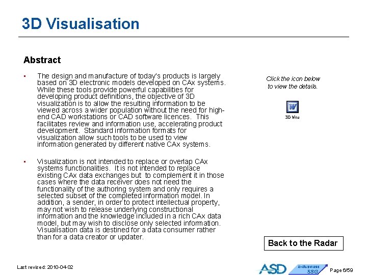
3 D Visualisation Abstract • The design and manufacture of today’s products is largely based on 3 D electronic models developed on CAx systems. While these tools provide powerful capabilities for developing product definitions, the objective of 3 D visualization is to allow the resulting information to be viewed across a wider population without the need for highend CAD workstations or CAD software licences. This facilitates review and information use, accelerating product development. Standard information formats for visualization allow such tools to be used to view information generated by different native CAx systems. • Visualization is not intended to replace or overlap CAx systems functionalities. It is not intended to replace existing CAx data exchanges but to complement it in those cases where the data receiver does not need the functionality of the authoring system and only requires a selected subset of the completed information model. In addition, a sender, in order to protect intellectual property, may not wish to release underlying constructional information and the knowledge included in a rich CAx data model, but may wish to disclose only selected information. Visualisation data is destined for a data consumer rather than for a data creator or updater. Last revised: 2010 -04 -02 Click the icon below to view the details. Back to the Radar Page 6/59
Archi. Mate Abstract • Archi. Mate is an open and independent enterprise architecture modeling language to support the description, analysis and visualization of architecture within and across business domains in an unambiguous way. • Archi. Mate is a technical standard from The Open Group and is based on the concepts of the IEEE 1471 standard. It is supported by various tool vendors and consulting firms. • Archi. Mate distinguishes itself from other languages such as Unified Modeling Language (UML) and Business Process Modeling Notation (BPMN) by its enterprise modeling scope. Click the icon below to view the details. Back to the Radar Last revised: 2014 -08 -18 Page 7/59
Boost. Aero Abstract • The Boost. Aero initiative was initially established as a joint French and Exostar initiative to achieve a standardized set of procurement e-trading messages, in order to avoid a proliferation of incompatible portals. This deliberately sought to build on the internationally agreed set of core components for eb. XML by working through UN/CEFACT, in order to ensure interoperability with other electronic trading environments. The initial set of messages has been developed and piloted, and is now being deployed in production use. • It was recognized at an early stage that the diversity of the global aerospace supply chain meant that the business objective could only be achieved by seeking global adoption of the standard. The Boost. Aero team therefore approached European ASD and American AIA seeking broader acceptance of their approach. The initial AIA due diligence process highlighted no major obstacles to use of Boost. Aero, but some need for modifications, similar to the European view. • The Boost. Aero standard has been adopted in 2009 by the Boost. Aero. Space Hub founders (i. e. Airbus, Dassault-Aviation, EADS, Safran, Thales) as the standard for exchanges on Air. Supply between customers and suppliers. This will generalize the use of Boost. Aero standards in the A&D Supply Chain. Last revised: 2016 -09 -13 Click the icon below to view the details. Back to the Radar Page 8/59
BPMN - Business Process Modelling Notation Abstract • BPMN is a standardized graphical notation that depicts the steps in a business process and the end-to-end flow of a business process. • It has been specifically designed to coordinate the sequence of processes and the messages that flow between different process participants in a related set of activities. It targets at facilitating communication between users, business analysts, vendors and service providers that need to communicate business process in as standardized manners, within e. Business context. Click the icon below to view the details. Back to the Radar Last revised: 2011 -11 -14 Page 9/59
COLLADA - COLLAborative Design Activity Abstract • • • The COLLADA format is a file format for exchange between 3 D applications (including games). COLLADA file is an XML file. The specification and the XML-based schema are publicly available. Collada 1. 5 specification was published in April 2008 by Khronos Group. Example of applications and software supporting COLLADA: 3 ds. Max, 3 Dvia, Blender, Photoshop. The features supported are: • • • Click the icon below to view the details. B-rep geometry / Mesh geometry / Level of Detail and Streaming Instantiation Transform hierarchy (rotation, translation, shear, scale, matrix) Compressed Exchange format Animation / Kinematics Physics (rigid bodies, constraints, rag dolls, collision, volumes) Shaders / Materials/ Textures / Lights /Skinning Cameras ISO/PAS 17506: 2012 Industrial automation systems and integration -- COLLADA digital asset schema specification for 3 D visualization of industrial data was published in July 2012. Back to the Radar Last revised: 2014 -08 -19 Page 10/59
eb. XML Core Components Abstract • The eb. XML Core Components Technical Specification can be employed wherever business information is being shared or exchanged amongst and between enterprises, governmental agencies, and/or other organizations in an open and worldwide environment. The Core Components provides business people, business document modelers and business data modelers, Business Process modelers, and application developers of different organizations a common set of vocabulary building blocks to support interoperability of business information. This interoperability covers both interactive and batch exchanges of business data between applications through the use of Internet and Web based information exchanges as well as traditional Electronic Data Interchange (EDI) systems. • The eb. XML Core Components Technical Specification, Version 2. 01 (eb. CCTS) is also published as ISO/TS 15000 -5. Under the governance of UN/CEFACT TBG 17, a library of approved core components is available for various standards organizations to use as building blocks for their transactions. • These core components provide the basis for the XML-based, e. Business vocabularies to be used for our global Aerospace & Defense industry. The core components are the foundation for the evolving Boost. Aero set of aerospace ebusiness transactions. Click the icon below to view the details. Back to the Radar Last revised: 2010 -04 -29 Page 11/59
FMI - Functional Mock-up Interface Abstract • • Functional Mock-up Interface (FMI) is a tool independent standard to support both model exchange and co-simulation of dynamic models using a combination of xml-files and compiled C-code. FMI improves and simplifies the exchange of dynamic system models between different modelling, simulation and cosimulation tools. Applications range from software/model/hardware-in-the-loop simulation to embedded systems. Initially developed in the European (ITEA 2) MODELISAR R&D project, FMI has been managed and developed since 2011 as a Modelica Association Project (MAP). • In the FMI approach, models are packaged in Functional Mockup Units (FMUs, with a given zip file structure) and can then be integrated in another simulation environment (model integration) or coupled at runtime in a distributed simulation (co-simulation). • FMI 2. 0, published in July 2014, provides significant enhancements compared to FM 1 1. 0, both for model exchange and for co-simulation. Moreover in FMI 2. 0 a significant effort has been done to merge the two FMI 1. 0 standards (Model Exchange and Co-Simulation) in one consistent standard. Click the icon below to view the details. Back to the Radar Last revised: 2018 -11 -12 Page 12/59
ISO 14306 - JT Edition 1 Abstract • • The JT format is an industry focused, high-performance, lightweight, flexible file format for capturing and repurposing three-dimensional product definition data that enables collaboration, validation and visualization throughout the extended enterprise It can contain any combination of 3 D approximate (faceted) data, 3 D exact boundary representation surfaces (NURBS, BSpline), Product and Manufacturing Information (PMI), and Metadata (textual attributes) either exported from the native CAD system or inserted by a product data management (PDM) system. It contains 3 possible 3 D exact representations (JT BRep, XT B-Rep and XT-Parasolid LWPA). ISO 14306: 2012 “JT Edition 1” was adopted by ISO in December 2012 as a 3 D visualization capability, in addition to the ISO 10303 series (STEP). ISO 14306: 2012 defines the syntax and semantics of the JT Version 9. 5 file format. Click the icon below to view the details. Back to the Radar Last revised: 2016 -09 -06 Page 13/59
ISO 14306 - JT Edition 2 Abstract • • • In 2012, ISO/DIS 14306: “JT file format specification for 3 D visualization” has failed the DIS Ballot and after the following resolution workshop, ISO TC 184/SC 4 has requested WG 12 to develop a New Work Item Proposal (NP) for a new edition of ISO 14306, called JT Edition 2, including but not limited to: • Replacing XT Brep and JT Brep with STEP curve, surface and Brep entity definitions. • Extending the scope to include external references to support semantic PMI for assemblies and other requirements from AP 242. The replacement of XT Brep and JT Brep is motivated by the dependencies to specific software and software vendors for non -ambiguous information sharing and efficient standard implementation. The scope of the second edition has not changed from the first edition and is focused on 3 D visualization, excluding product data exchange and long term archiving. Click the icon below to view the details. Back to the Radar Last revised: 2016 -09 -06 Page 14/59
ISO 22745 Open technical Dictionaries and automated data exchange Abstract • The initiative is intended to enshrine the practice and capability of Electronic Open Technical Dictionaries and used to support automated data transactions between participating entities. • It provides a common structure for defining open technical dictionaries as repositories of sets of terminology derived from other standards, with links back to the originating document. Such repositories can accommodate multiple definitions of the same term, although each definition will have its own unique identification • The dictionaries can then be used to set up catalogues and classification schemes using the terminology in the dictionaries to define property-values pairs, with terms resolvable over the Internet using the unique identifiers. • A further application of the dictionaries links the properties of features in STEP product definitions to the NATO Codification Scheme, and also to automatically generate STEP product definitions from the characteristic properties. • This standard in conjunction with ISO 8000 Pt 110 has been used in trials to generate automatically from source technical descriptions in accordance with the US Federal Item Identification Guides and NATO Codification System. The trials used a schema provided by ECCMA as part of the only currently accredited ISO 22745 OTD (ECCMA Open technical Dictionary) Click the icon below to view the details. Back to the Radar Last revised: 2011 -11 -28 Page 15/59
ISO 8000 - Data Quality Abstract • The ISO 8000 series of standards covers data quality activities, terminology, characteristics (criteria) and testing. Data quality is a pervasive problem for organizations across the globe and has a major economic impact. No one nation can afford to develop a unique perspective on the solution to this problem. The standard is applicable to all types of industrial data, including master data, transaction data and product data. • ISO 8000 defines characteristics that can be tested by any organization in the data supply chain to objectively determine conformance of the data to ISO 8000 does not require external certification of data quality. Therefore, data quality conformance can be self-controlled. • ISO 8000 provides a framework for improving data quality that can be used independently or in conjunction with quality management systems. Click the icon below to view the details. Back to the Radar Last revised: 2012 -03 -14 Page 16/59
EN 9300 LOTAR - Long Term Archiving and Retention Abstract • • The LOTAR project is designed to provide a capability to preserve digital aerospace and defence product information in a standard neutral form that can be read and reused throughout its lifecycle, independent of changes in the IT application environment originally used to create it. The multi-part standard covers the requirements, the information content and the processes required to ingest, store, administer, manage and access the information. The LOTAR international project brings together the works started in Europe by ASD Stan LOTAR, supported by Pro. STEP i. Vi. P, and the US similar works started by PDES Inc and AIA, under the auspices of the International Aerospace Quality Group (IAQG). This general recommendation of the ASD SSG regarding the LOTAR standards are completed by other SSG recommendations per specific domains: • • LOTAR 3 D PMI LOTAR PDM LOTAR Composite LOTAR Electrical Last revised: 2012 -10 -05 : long term preservation of 3 D PMI information, : long term preservation of PDM information. : long term preservation of Composite information. : long term preservation of Electrical Harness information, Click the icon below to view the details. Back to the Radar Page 17/59
EN 9300 -1 XX - Long-Term Archiving and Retrieval of 3 D Geometry, CAD structure and Product Manufacturing Information (LOTAR 3 D CAD) Abstract • • • The LOTAR project is designed to provide a capability to preserve digital aerospace and defence product information in a standard neutral form that can be read and reused throughout its lifecycle, independent of changes in the IT application environment originally used to create it. This document focuses on the EN 9300 -1 XX family for long term archiving and retrieval of CAD mechanical information, including assembly structure, 3 D Geometric shape representation (explicit and implicit), associated Product and Manufacturing Information (PMI), and machining form features. The EN 9300 -1 XX family is organized as a sequence of parts, each building on the previous in a consistent way. Some of the EN 9300 -1 XX standards are adopted and exploited by the Aerospace and Defence industry. As technology matures additional parts will be released in order to support new requirements within the aerospace community. Last revised: 2012 -10 -05 Click the icon below to view the details. Back to the Radar Page 18/59
EN 9300 -2 XX - Long-Term Archiving and Retrieval of Product Management Data & Configured Mechanical Product Structure (LOTAR PDM) Abstract • • • The LOTAR project is designed to provide a capability to preserve digital aerospace and defense product information in a standard neutral form that can be read and reused throughout its lifecycle, independent of changes in the IT application environment originally used to create it. This document focuses on the ASD EN 9300 -2 XX family for long term preservation of the Product Management Data Information throughout lifecycle. The EN 9300 -2 XX family is organized as a sequence of parts, each building on the previous in a consistent way. Some of the EN 9300 -2 XX standards are draft. As technology matures additional parts will be released in order to support new requirements within the aerospace community. Click the icon below to view the details. Back to the Radar Last revised: 2012 -10 -05 Page 19/59
EN 9300 -3 XX - Long-Term Archiving and Retrieval of Composite Information (LOTAR Composite) Abstract • • • The LOTAR project is designed to provide a capability to preserve digital aerospace and defence product information in a standard neutral form that can be read and reused throughout its lifecycle, independent of changes in the IT application environment originally used to create it. This document is focused on the EN 9300 -3 XX family for the long term archiving and retrieval of the composite structures. The EN 9300 -3 XX family is organized as a sequence of parts, each building on the previous in a consistent way. EN 9300 -3 XX standards are in development and will be adopted and exploited by the Aerospace and Defense industry. As technology matures additional parts will be released in order to support new requirements within the aerospace community. Click the icon below to view the details. Back to the Radar Last revised: 2012 -10 -05 Page 20/59
EN 9300 -4 XX - Long-Term Archiving and Retrieval of Electrical Harness Information (LOTAR Electrical Harness) Abstract • • • The LOTAR project is designed to provide a capability to preserve digital aerospace and defence product information in a standard neutral form that can be read and reused throughout its lifecycle, independent of changes in the IT application environment originally used to create it. This document is focused on the EN 9300 -4 XX family for the long term archiving and retrieval of Electrical Harness information. The EN 9300 -4 XX family is organized as a sequence of parts, each building on the previous in a consistent way. Some of the EN 9300 -4 XX standards are adopted and exploited by the Aerospace and Defense industry. As technology matures additional parts will be released in order to support new requirements within the aerospace community. Click the icon below to view the details. Back to the Radar Last revised: 2012 -10 -05 Page 21/59
MIMOSA Machinery Information Management Open Systems Alliance Abstract • MIMOSA is a not-for-profit trade association dedicated to developing and encouraging the adoption of open information standards in operations and maintenance (O&M) in manufacturing, fleet, and facility environments. • MIMOSA has developed two information-exchange open standards, providing for example metadata reference libraries and a series of information-exchange standards using XML and SQL: • A standard for management applications: Open Systems Architecture for Enterprise Application Integration (OSA-EAI™) • • • Click the icon below to view the details. Includes modelling, metadata, source, query/response, historicity, etc. Applicability: Diagnostics, prognostics, trending, test, and maintenance, Acquisition of built-in-test results, storage of raw and transformed data, and exchange of data for analysis and viewing A standard for condition-based maintenance: Open Systems Architecture for Conditioned Based Maintenance (OSA-CBM™) • • Object interfaces (modules with exposed methods) Platform oriented (helicopter, vehicle, ship). Back to the Radar Last revised: 2014 -08 -25 Page 22/59
Modelica Abstract • • • Modelica® is a non-proprietary, object-oriented, declarative, equation based language to conveniently model complex physical systems containing, e. g. , mechanical, electrical, electronic, hydraulic, thermal, control, electric power or process-oriented subcomponents. . Modelica is a free language developed by the (non-profit) Modelica Association since 1996. The Modelica Association develops also the a free library for multi-domain models: the Modelica Standard Library. The Modelica design effort was initiated in September 1996. The goal was to develop an object-oriented language for modeling of technical systems in order to reuse and exchange dynamic system models in a standardized format. Modelica supports behaviours described by differential, algebraic, and discrete equations, enabling a large spectrum of 0 D/1 D simulations. 3 D simulation based on partial differential equations (e. g. FEM, CFD) is not supported, but results of such simulations can be integrated (e. g. using surrogate models). Last revised: 2013 -09 -09 Click the icon below to view the details. Back to the Radar Page 23/59
Mo. SSEC - Modelling and Simulation in Collaborative Systems Engineering Context Abstract • • The ISO Mo. SSEC project is designed to provide a capability to share modelling and simulation (M&S) information in a collaborative systems engineering context, and to enable full traceability and reuse of this information throughout the product lifecycle and independent of the specific IT applications used across collaborating enterprises. The targeted standard covers a core subset of systems engineering information content and the related practices and information services necessary to support engineering collaboration. The ISO Mo. SSEC international project brings together the works started in Europe by CRESCENDO and TOICA Consortia to apply AP 233/AP 239 for this scope, and similar works in Europe and US motivated by similar goals. The project deliverable will be a new STEP Application Protocol [AP] under ISO TC 184/SC 4 within the New STEP Architecture and utilising a subset of the AP 239/AP 242 harmonised information model. This AP will include an activity model for usage guidance; AP-level definitions for agreed implementation technologies; conformance classes; documentation and dissemination material. Last revised: 2016 -09 -06 Click the icon below to view the details. Back to the Radar Page 24/59
OAGIS Open Applications Group Integration Specification Abstract • The specification provides a set of standardized XML messages for use throughout the supply chain. It defines a series of Business Object Definitions (BODs) to support the standardized exchange of typical messages used in B 2 B applications for commercial supply chain and accounting transactions. • Each BOD comprises a Verb (get, show, list, process etc. ) and a Noun (purchase order, shipping list, invoice, Bo. M etc. ). Some 16 verbs and 75 nouns are defined by OAGIS 9. Messages can be tailored to meet local user requirements. Brief scenarios are provided to illustrate usage of most BODs. • EDS used selected nouns from OAGIS 8 as an integration model for the UK Mo. D Supply Enterprise Information Architecture (EIA) hub. OAGIS 8 has also been applied to a few messages linking the Log Info System, LITS, to the EIA Hub on the Tornado ATTAC project. • OAGIS 9 differs from the earlier versions due to alignment with the eb. XML Core Components Library (see separate blip) developed by OASIS and UN/CEFACT, which is the agreed international approach for transactional messages. There has been a deliberate decision to break upward compatibility to address this alignment. • The specification is freely available for download from the OAGi site Click the icon below to view the details. Back to the Radar Last revised: 2016 -09 -13 Page 25/59
OSLC - Open Services for Lifecycle Collaboration Abstract • Open Service for Lifecycle Collaboration (OSLC) is an open community, originally proposed in 2008, to define a set of specifications that enable integration of software development and more broadly Application Lifecycle Management (ALM) and Product lifecycle Management (PLM) products and services. • The OSLC initiative is divided up into a dozen workgroups and each workgroup develops specifications in context of a specific part of the lifecycle. For example, there are workgroups for Change Management, Quality Management, Requirements Management, Software Configuration Management and Build Automation. • As of June 2013, the OSLC initiative is a Member Section of the Open Standard Organization OASIS. • The OSLC specifications build on the W 3 C Resource Description Framework (RDF), Linked Data and REST, enabling integration at data level via links between related resources. OSLC resources are defined in terms of RDF properties. Operations on resources are performed using HTTP. OSLC also specifies user interface techniques to enable preview, creation and selection of links. Last revised: 2014 -18 -08 Click the icon below to view the details. Back to the Radar Page 26/59
PRC/U 3 D - Open Services for Lifecycle Collaboration Abstract • • The PDF format is a file format for the representation of documents. PDF allows to preserve the layout (text, font, graphics and other information). It is independent of the operating system and the software. PDF was originally developed by Adobe Systems in 1993. The open format has been published by the ISO in 2008. PDF/E is a subset of pdf. The intent is the exchange of engineering and technical data. • • Click the icon below to view the details. The part 1 of PDF/E published by the ISO in 2008 include the U 3 D format. The part 2 of PDF/E will include the PRC 1. 0 format. U 3 D is a file format for 3 D data. U 3 D was originally develop by a group including Intel, Boeing, HP, Adobe Systems. U 3 D standard has been published in 2006 by ECMA international. PRC is a file compressed format allows to have different representation of a 3 D model. PRC was originally developed by TTF. PRC format has reached the Draft International Standard stage in 2012. Back to the Radar Last revised: 2014 -08 -19 Page 27/59
PAS 55: 2008 BSI Publically Available Specification Asset Management Abstract • PAS 55 defines the requirements for an integrated and cohesive Asset Management system, providing a clear “line of sight” from organization direction and goals down to individual, day-to-day activities. • Asset Management in this context is the systematic and coordinated activities and practices through which an organization optimally manages assets and systems, their performance, risks and expenditures over their life cycles for the purpose of achieving the organisational strategic plan. • To ensure consistency with other related management system standards, PAS 55 was documented as a specification, with the information on implementing asset management distilled into key requirements. The criterion for including such requirements has been that, without them, the asset management system would be regarded as deficient. • This Specification is applicable to any organization where physical assets are a critical factor in achieving its goals. Click the icon below to view the details. Back to the Radar Last revised: 2013 -09 -09 Page 28/59
RFID Application Standards Abstract • Radio Frequency Identification (RFID) provides the capability to attach identity and other information to a physical object in the form of an electronic tag, which can be accessed remotely through a radio frequency reader and transmitted to application software. • RFID tag hardware consists of a computer chip plus antenna which can be read from, and optionally written to, using an RF reader via radio frequency. Tag and Reader can operate in active mode with battery powered tags or in passive mode using reader power. • Basic RFID is used to locate, track and identify assets and commodities, and to trigger events such as information exchange. New RFID capabilities offer a range of business opportunities for attaching additional information to a tagged product or shipping container and exploiting that information to streamline business processes. • RFID applications are now being developed for Transportation, Logistics, Material / Inventory Management and Aircraft Maintenance in the Aerospace and Defense (A&D) Industry. • ERP and MRP applications supporting RFID applications • Multiple Industry verticals defining cross industry RFID data vocabularies Last revised: 2010 -03 -10 Click the icon below to view the details. Back to the Radar Page 29/59
S 1000 D - Specification for Technical Publications Abstract • • • The international specification for technical publications using a common source database, commonly known as S 1000 D, has been produced to establish standards for the technical documentation of any civil or military vehicle or equipment. It is based on international standards such as XML and CGM for production and use of electronic documentation. In addition, it defines a Common Source Data Base (CSDB) to provide source information for compilation of the publications and for use in electronic logistics information systems to deliver modules of information direct to the user. S 1000 D is linked to the PLCS development, which enables the compilation of technical documentation direct from the current product structure. The specification also includes rules and XML Schemas to enable the production of SCORM-compliant Web Based Training (WBT). Click the icon below to view the details. Back to the Radar Last revised: 2014 -08 -13 Page 30/59
S 2000 M International specification for material management specification Abstract • • The ASD S 2000 M defines the Materiel Management processes and procedures to be used in support of any military Product. Although this Specification is designed for military Product support, it may nevertheless be used for the support of any non-military Product. The S 2000 M describes the business relationship between Industry and Customer by providing the process flow, the relevant transactions and data elements used. The S 2000 M is organized into basic chapters: • • Chapter 1 A Provisioning Chapter 1 B NATO Codification Chapter 2 Procurement Planning Chapter 3 Order Administration Chapter 4 Invoicing Chapter 5 Repair Administration Chapter 6 S 2000 M Light Last revised: 2011 -09 -30 Click the icon below to view the details. Back to the Radar Page 31/59
S 3000 L - International procedure specification for Logistic Support Analysis LSA Abstract • • With the introduction of a new and complex technical product, all logistic requirements must be made available in a timely manner. This requires a process to ensure consideration of logistic requirements during the design of the product and support the establishment of a proper support system. The LSA process includes a number of analysis activities concerning a wide range of technical and logistic considerations and the careful documentation of the results of these analysis activities. The achievement of proper supportability is of crucial importance concerning operation and life cycle costs. Early consideration of logistic aspects is increasingly important with regard to both operational and economic aspects. A product that cannot be operated and maintained properly and cost effectively is not acceptable to the end user. The purpose of the specification S 3000 L is to cover the activities and requirements governing the establishment of the LSA process. Click the icon below to view the details. Back to the Radar Last revised: 2015 -03 -31 Page 32/59
S 4000 P - International specification for developing and continuously improving preventive maintenance Abstract • • According to the ASD scope, S 4000 P must cover all kind of Product types including any complex technical platform, system, equipment or facility (eg. on air/sea/land, under sea, under ground, in space). The main purpose of ASD S 4000 P is to assist regulatory authorities and all parties involved in the analysis process in developing and releasing initial Preventive Maintenance Task Requirements (PMTR) and intervals for new Products prior entry into service. The S 4000 P analysis methodologies remain applicable for later optimizations/modifications of the Product design in Product systems and/or of Product structure and/or of Product zones during the Product in-service phase. Once developed, authorized and packaged into interval clusters in a Product Operator Maintenance Program (OMP), the S 4000 P In-Service Maintenance Optimization (ISMO) process enables continuous improvement of Product maintenance during the in-service phase. Every development of a PMTR or later improvements of a preventive maintenance task for a Product is linked to at least one of the following aspects: • Ensure / maintain Product safety, including safety/emergency systems • • • and/or emergency equipment, Avoid any conflict with law and/or significant impact on environmental integrity (ecological damage) during Product mission/operation and/or maintenance, Optimize mission/operational capability/availability of the Product, Optimize Product economy (Life Cycle Costs = LCC). Last revised: 2014 -07 -08 Click the icon below to view the details. Back to the Radar Page 33/59
S 5000 F - Operational and Maintenance Data Feedback Abstract In-service data feedback is one of the most important functions of in service support. It enables fleet managers, support managers and technical system manufacturers to perform a thorough analysis of operational and maintenance performance of a technical system. The results of the analysis can be the basis for: • enhancement of the maintenance and support concept • improvement of the product or the system by modifications and retrofit activities • sophisticated operational planning • management of requirements and contracts The overall aim to be achieved through in-service data feedback is the increase of fleet availability and optimization of effectiveness. In addition the in-service data feedback information is a firm requirement by industry to agree to and manage Performance Based Logistics (PBL) contracts and to fulfil their obligations in the regard to product liability. The aim with S 5000 F is to handle information from the in service operation (from the operator to the Product manufacturer or the maintainer) or vice-versa during the in-service phase. The processes used for this are described in the specification, with the focus on specific use cases that are associated to activities that typically require in-service data feedback. The association of data feedback to specific use cases ensures that no unnecessary information is requested from the field. Last revised: 2017 -02 -02 Click the icon below to view the details. Back to the Radar Page 34/59
S 6000 T - International specification for Training Analysis and Design Abstract Training and Training Support consists of the processes, procedures, techniques, training devices and equipment used to train personnel to operate and support a system. The development of an effective training solution is critical to ensure the alignment between system design and the overall support of that system. Click the icon below to view the details. S 6000 T is taking a process based architectural approach and detailing the processes steps required to complete these 2 phases, to understand the data inputs and outputs for each of these steps. The S 6000 T working group is using Department of Defense Handbook 29612, Instructional Systems Development/Systems Approach to Training and Education, as well as several international guidance’s to understand harmonize the process steps and data requirements. S 6000 T is the latest S-series specification being drafted by AIA/ASD with the purpose of standardizing the data delivered by the different supportability elements as well as to standardize the data exchanges between the different support elements. Back to the Radar Last revised: 2018 -11 -30 Page 35/59
SX 000 i - International guide for the use of the S-Series Integrated Logistics Support (ILS) specifications - (“ILS Guide”) Abstract • Integrated Logistic Support (ILS) is the integrated management of the definition and development of all support resources, using a common process and methodology, so as to harmonize the different support elements, prevent unnecessary rework and reduce overall life-cycle costs. • The SX 000 i has been developed to ensure the compatibility and the commonality of ILS processes among the AIA/ASD S-Series ILS specifications. By providing a single framework that documents the global ILS process and interactions, and by defining governance requirements for the S-Series ILS Specifications, the SX 000 i and S-Series Specifications will enable all stakeholders to apply common logistics processes so as to share and exchange data securely through the life of products and services. • Through the secure and standardized exchange of data and information, product performance and life cycle cost can be more easily analyzed and optimized, and collaboration between customers and industry can be simplified. Last revised: 2017 -02 -02 Click the icon below to view the details. Back to the Radar Page 36/59
SX 001 G - Glossary for the S-series ILS specifications Abstract • With the drive for an integrated set of Integrated Logistic Support (ILS) specifications, the need arises for common definitions, common terminology, common abbreviations and data elements. This cannot be achieved if these elements are spread across different specifications. The SX 001 G glossary will provide a common reference across all S-series specifications. Click the icon below to view the details. Back to the Radar Last revised: 2015 -02 -10 Page 37/59
SX 002 D - Common data model for the S-Series ILS Specifications Abstract • • • With the drive for an integrated set of Integrated Logistic Support (ILS) specifications, the need arises for interoperability between the different data models of the different specifications. This cannot be achieved unless a common core is hared across all specifications The SX 002 D defines a Common Data Model across all SSeries ILS specifications, and will cover all elements shared by at least two specifications. SX 002 D is based on AP 239 and will therefore allow the integration with other domains, such as requirements (AP 233) or engineering (AP 242) as soon as the different APs have been all integrated. Click the icon below to view the details. Back to the Radar Last revised: 2015 -02 -10 Page 38/59
SAML - Security Assertion Markup Language Abstract • SAML Defines a protocol to exchange, identification and authentication information in order to enable security and confidence through Internet collaboration. • SAML provides distributed SSO functions on the Internet , allowing people to be identify in their own user management system and access distant resources (applications and data) using a unique and proven identity. Click the icon below to view the details. Back to the Radar Last revised: 2010 -03 -11 Page 39/59
SCORM - Sharable Content Object Reference Model 2004 Abstract • • • SCORM describes a technical framework that references a harmonized set of e-learning-based guidelines, specifications and standards. Internationally proven as a training technology, implementations have succeeded through use of a content model to ensure consistent run-time environment behaviours that manage and track distributed learning events across elearning communities. SCORM is built upon the work of the Aviation Industry Computer-Based Training (CBT) Committee (AICC), the IMS Global Learning Consortium, Inc. , the Institute of Electrical and Electronics Engineers (IEEE), the Alliance for Remote Instructional Authoring and Distribution Networks for Europe (ARIADNE) and others. It creates one unified "reference model" of interrelated technical specifications and guidelines that meet United States Department of Defense (Do. D) high-level requirements for Web-based learning content and systems. South Korea’s Education Ministry has implemented SCORM across all grade levels to manage after-school tutorial programs. SCORM has proven to support a diversity of content and communities. Last revised: 2012 -10 -05 Click the icon below to view the details. Back to the Radar Page 40/59
SPEC 2000 – ATA E-Business Specification for Materiels Management Abstract • • ATA Spec 2000 is a global aviation specification to automate the business processes and information exchange associated with aircraft parts, materiel, maintenance and reliability. This specification encompasses a wide variety of information exchange and is used broadly by the world's airlines and suppliers. Spec 2000 was up to 2016 structured into major chapters, each designed to stand alone for ease of understanding, as well as ease of implementation. Appendices are assigned to those subjects common to each chapter. • • • • • Chapter 1 - Provisioning Chapter 2 - Procurement Planning - Download Free Chapter 3 - Order Administration Chapter 4 - Customer Invoicing Chapter 5 - Information and Data Exchange Chapter 6 - Communications Commands Chapter 7 - Repair Order Administration Chapter 8 - Repair/Overhaul Planning Chapter 9 - Automated Identification and Data Capture - Purchase Separately Chapter 10 - SPEC 2000/ASC X 12 Implementation Guide Chapter 11 - Reliability Data Collection/Exchange - Purchase Separately Chapter 12 - Airline Inventory Redistribution System (AIRS) - Download Free Chapter 13 - Industry Performance Metrics Chapter 14 - Warranty Chapter 15 - Delivery Configuration Data Chapter 16 - Electronic Parts Certification Forms - Download Free Chapter 17 - Electronic Logbook Last revised: 2018 -11 -12 Click the icon below to view the details. Back to the Radar Page 41/59
SPEC 2300 - Data Exchange Standard For Flight Operations Abstract • • The purpose of this specification is to provide a concise set of information standards and guidelines for the management, configuration and interchange of flight operations technical content for fixed-wing and rotorcraft. This Specification is focused on a data-centric approach, addressing the aircraft operator’s current and planned future operational / business requirements of these data. A corner stone of this specification is that these data are stored once, reusable without rework, and the interchange. This specification is designed to enable the cost-effective and efficient exchange of digital data between information providers and information users for Flight Operations. The primary goals, features, and objectives are: • Exchange of information based on non-proprietary standards. • A standard architecture that is data-centric as opposed to document-centric, • • • and relies on modular, reusable components. Information from multiple manufacturers is received by operators in a single, consistent manner. Facilitate identification of changes to the data. Facilitate modification or re-authoring of information. Separate presentation of information from the content of the information, enabling output to multiple formats. Enable identification of information based on its applicability to specific aircraft or fleets. Facilitate re-use of content for different audiences, e. g. , Crew Use During Flight, In-House Training, Engineering, Computer-Based Training (CBT). Last revised: 2018 -11 -12 Click the icon below to view the details. Back to the Radar Page 42/59
STE 100 - ASD Simplified Technical English - International specification for the preparation of technical documentation in a controlled language Abstract • • • ASD-STE 100 (European Community Trade Mark No. 004901195) is an international specification for the preparation of maintenance documentation in a controlled language. A controlled language is a form of language with special restrictions on grammar, style and vocabulary usage. It was developed in the early Eighties (as AECMA Simplified English) to help the users of English-language documentation to understand what they read. The ASDSTE 100 provides a set of Writing Rules and a Dictionary of controlled vocabulary. The Writing Rules cover aspects of grammar and style; the Dictionary specifies the general words that can be used. These words were chosen for their simplicity and ease of recognition. In general, there is only one word for one meaning, and one part of speech for one word. In addition to the specified general vocabulary, ASD-STE 100 accepts the use of company-specific or project-oriented technical words, provided that they fit into one of the categories listed in the Specification. Control of any additional specific vocabulary is, of course, the responsibility of the company or the project itself. Last revised: 2017 -02 -01 Click the icon below to view the details. Back to the Radar Page 43/59
STEP - Standard for the Exchange of Product model data Abstract • STEP provides a comprehensive set of internationally-agreed integrated information models to address the problem of exchanging, sharing and archiving product information across dissimilar computer applications throughout the lifecycle of the product. • Deployment of the STEP standard enables companies to have a proven single definition for all the product-related information related to individual products throughout their lifecycle, independent of changes in process and information technology. The standard will enable suppliers to deliver and receive support information in a consistent form, irrespective of the source. Interoperability is facilitated by the adoption of common subsets of the standard, known as Application Protocols to support particular information flows. Click the icon below to view the details. Back to the Radar Last revised: 2014 -10 -23 Page 44/59
STEP AP 203 - Configuration controlled 3 D design of mechanical parts and assemblies Abstract • • ISO 10303 -203: 2011 specifies the application protocol for “Configuration control 3 D design” edition 2. The following are within the scope of ISO 10303 -203: 2011: • • • Click the icon below to view the details. Products that are mechanical parts and assemblies; Product definition data and configuration control data pertaining to the design phase of a product's development; Representation of an instance of a part in an assembly through its usage in a sub-assembly; Three dimensional shape representations of a part Geometric validation properties to allow the translation of geometric shape representations (advanced boundary representation and faceted boundary representation solids) to be checked for quality; Geometric and dimensional tolerances applied to geometric shape representations; Materials and their composition of chemical substance; Composite material structure and shape; Catalogue data characterized by property value pairs; Three dimensional presentation of product data: Technical drawings as two dimensional presentation of product data. The first edition has been published by ISO in 1994 and the second edition has been published by ISO in 2011, in a modular form. Back to the Radar Last revised: 2013 -04 -05 Page 45/59
STEP AP 209 - Multidisciplinary analysis and design Abstract • • • In the context of Design/Analysis integration, STEP AP 209 is a standard for exchange and long term archiving of information between iterative design and analysis stages of the product life cycle. First edition of STEP AP 209 was published in 2001 under the name “Composite and Metallic Structural Analysis”. The primary intent of the standard is to combine CAD, CAE and PDM capabilities to enable sharing of PDM controlled composite and metallic design, analysis, and material properties information. Augmenting shared information between design and analysis, both disciplines have separate but related product definitions allowing support of independent configuration control between the disciplines. Transfer between CAD 3 D shape and CAE analysis information may be bidirectional enabling the feedback of information in the iterative design/analysis environment. A second edition of STEP AP 209, renamed “Multidisciplinary analysis and design” is in final stage of development with the DIS submitted end of June 2013. On top of its migration to the modular architecture, STEP AP 209 ED 2 has enlarged its coverage beyond the STEP AP 209 ED 1 classical Finite Element Analysis capabilities: • • Click the icon below to view the details. CFD, mainly based upon the CGNS standard; Generalized structured and unstructured analysis and mesh capabilities, developed under the European Union GEM program; Complete discrete/continuous mathematical field representation capability, based upon the David Taylor Labs/Boeing DT-NURBS package. The result is that STEP AP 209 ED 2 will now address a much wider set of multi-disciplinary analysis and optimization problems. Back to the Radar Last revised: 2015 -02 -10 Page 46/59
STEP AP 210 Electronic Assembly Interconnect and Packaging Design Abstract • In 2001, ISO published the first edition of a STEP Application Protocol for Electronic Assembly Interconnect and Packaging Design (AP 210) as an International Standard. This Application Protocol (AP) provides the groundwork for significant advances in product data reuse and cycle time reduction by defining a standardized, computer-interpretable method for representing the design of: • • • Click the icon below to view the details. Assemblies with electrical content at multiple levels of product hierarchy, Assemblies being designed jointly by electrical and mechanical departments, Interconnect designed using layered abstraction, typically Printed Circuit Boards (PCBs). This AP achieves a significant breakthrough in re-usable component models, allowing component suppliers to provide 3 D product models with electrical intelligence integrated with catalog data in a computer-interpretable neutral form for the first time. This achievement was reached through a coordinated effort involving numerous Fortune 500 companies and government organizations including Rockwell Collins Inc. , Boeing, Delphi. Delco Electronic Systems, IBM, the US Naval Supply Systems Command RAMP Program Office, and NIST. A second edition of AP 210 based on STEP modules consistent with APs such as AP 203, AP 209, AP 233 and AP 239 is scheduled for publication in 2010. Last revised: 2011 -01 -11 Back to the Radar Page 47/59
STEP AP 212 - Electrotechnical design and installation Abstract • • • AP 212 is an international standard that specifies data representation for the exchange and sharing of electromechanical plants and industrial systems design information. It addresses electrical product definition necessary to support electrical cable tray: current analysis, equipment, lighting, cable sizing, electrical connectivity checks and cable tray interference detection. This application protocol does not impose any restriction on the usage of these systems for particular applications - equipment for power-transmission, distribution, and generation, electrical machinery, electric light, electric heat, control and automation systems are all in scope. It was an initiative of the electrical industry and has being developed in cooperation with Pro. STEP Gmb. H, with the help of the German Electrotechnical Committee (DKE) and with the cooperation of other industrial consortia, e. g. GOSET(F) and PDES Inc. (USA), and is standardized internationally as a joint effort of IEC/TC 3 and ISO/TC 184/SC 4. The first edition has been published in 2001 by ISO and since then no further updates or preparation for a new edition have been requested by industry. Click the icon below to view the details. Back to the Radar Last revised: 2011 -01 -11 Page 48/59
STEP AP 214 Core data for automotive mechanical design processes Abstract • This application protocol is one of the relevant STEP APs available for ASD deployment (c. f. STEP blip for more information on this set of standards). • STEP AP 214 provides an integrated information models to address the problem of exchanging, sharing and archiving product information related to mechanical design process across dissimilar computer applications throughout the lifecycle of the product, including Product Data Management systems and Computer Aided Design tools dealing with different kind of geometrical representations and metadata allowing to describe product structure, document structure, configuration management information, change process information, effectivity information, person and organization, etc. • Deployment of the STEP AP 214 standard enables companies to have a proven single definition for all the product-related information used for mechanical design process, with different views on lifecycle phases considered by the designers. Click the icon below to view the details. Back to the Radar Last revised: 2013 -04 -05 Page 49/59
STEP AP 233 - Systems Engineering Abstract • This application protocol is one of the relevant STEP APs available for ASD deployment (c. f. STEP blip for more information on this set of standards). • STEP AP 233 provides an integrated information models to address the problem of exchanging, sharing and archiving product information related to system engineering design process across dissimilar computer applications throughout the lifecycle of the product, including Product Data Management systems and Computer Aided Design tools dealing with different kind of system representations and metadata allowing to describe system structures, document structure, configuration management information, change process information, effectivity information, person and organization, etc. • Deployment of the STEP AP 233 standard enables companies to have a proven single definition for all the product-related information used for mechanical design process, with different views on lifecycle phases considered by the system designers. Click the icon below to view the details. Back to the Radar Last revised: 2010 -04 -02 Page 50/59
STEP AP 235 Engineering properties for product design and verification Abstract • • STEP AP 235 defines the context, scope, and information requirements for properties of products that can be used for product design and design validation, the testing, measurement and approval processes used to determine those properties and specifies the integrated resources necessary to satisfy these requirements. Considering that the value of an engineering property of a product is dependent on the process used to measure the property value and on the conditions used in that process, AP 235 provides the means to associate a property value explicitly to the conditions in which it was measured, and thus provide an audit trail to the origins of data values that can be used in product design. AP 235 enables to represent the relationships between the test piece, the sample and the original product, as the measurement procedure generally requires a representative test piece with specific shape and dimensions. AP 235 handles the method used to process the engineering properties from the testing results (e. g. central value and associated uncertainty). Click the icon below to view the details. Back to the Radar Last revised: 2016 -09 -06 Page 51/59
STEP AP 239 - Product Life Cycle Support (PLCS), Edition 2 Abstract • PLCS provides an internationally-agreed information model to address the problem of keeping the full set of information related to a product in alignment with that product throughout its lifecycle. The required information includes product data management, task descriptions, operating states, planned and unplanned maintenance and complete historical records • Deployment of the PLCS standard will enable companies to have a single definition for all the product-related information related to individual products throughout their lifecycle, independent of changes in process and information technology. The standard will enable suppliers to deliver and receive support information in a consistent form, irrespective of the source. Interoperability will be facilitated by the adoption of common subsets of the standard, known as Data Exchange Sets (DEXs) to support particular logistics information flows, and the use of common reference data libraries to configure the standard for operational use. Last revised: 2016 -09 -06 Click the icon below to view the details. Back to the Radar Page 52/59
STEP AP 239 - Product Life Cycle Support (PLCS), Edition 3 Abstract • In 2015, a divergence risk was identified between the different versions of STEP PLCS (ISO AP 239 ed 1, ed 2 and the corresponding OASIS PSM specification) and product support standards (AIA-ASD S-Series suite of ILS specifications, SAE). To solve this issue, a PLCS Edition 3 project was proposed to ISO end of 2015. • Objective of this PLCS Edition 3 are to: o Harness current product life cycle standardization efforts, such as ISO 10303 -239 ed 1, ed 2, ASD/AIA S-Series, and SAE GEIA-STD-0007 as inputs in developing baseline requirements for ISO 10303 -AP 239 ed 3. o Ensure interoperability with AP 242 and other STEP APs through the new STEP architecture. o Incorporate requirements from implementation experience and the Product Support standards. • The project has started in 2016, with the objective to deliver a Draft International Standard in 2018. Click the icon below to view the details. Back to the Radar Last revised: 2016 -09 -06 Page 53/59
STEP AP 242 Managed Model Based 3 D Engineering, Edition 1 Abstract • • • For 20 years a significant amount of effort has been made by the Aerospace and Automotive industry to develop two parallel STEP standards: AP 203 edition 1 was published in 1994, primarily driven by Aerospace and Defence requirements and developed and maintained by PDES, Inc. AP 214 edition 1 was published in 2001, driven primarily by automotive requirements, and developed and maintained by the Pro. STEP i. Vi. P and SASIG organizations. The ASD SSG working jointly with Pro. STEP i. Vi. P, and NIST working jointly with PDES, Inc. have identified an opportunity for a convergent AP, based on AP 214 edition 3 and AP 203 edition 2. As a response, a new project has been launched by ISO TC 184/SC 4: ISO 10303242 in 2010. The main technical requirement for AP 242 ed 1 is to become the cornerstone standard of the cross-process capabilities for interoperability of core engineering design information under configuration management, that is to say, • Providing specifications for exchange and long term archiving, • Providing a consistent business object model used for XML exchange and PLM web services, and • Providing a data model for 3 D tessellated model Click the icon below to view the details. Back to the Radar Last revised: 2015 -02 -10 Page 54/59
STEP AP 242 Managed Model Based 3 D Engineering, Edition 2 Abstract • STEP AP 242 edition 1 standard is the result of the convergence of STEP AP 203 ED 3 and AP 242 ED 3; this standard is described by a specific component summary: Application Protocol 242 “Managed Model Based 3 D Engineering” edition 1. • The industry has launched a project to increase the functionalities of the edition 1 to several domains. The goal is to consolidate the key role of STEP AP 242 as the backbone information model for Core 3 D design information, covering progressively the different technical disciplines requested by the manufacturing industries. • The main extensions of AP 242 edition 2 are for Electrical harness for design and construction, and for 3 D additive manufacturing / 3 D printing design information. Click the icon below to view the details. Back to the Radar Last revised: 2014 -10 -22 Page 55/59
Sys. ML - Systems Modeling Language Abstract • • • Sys. ML is a standardized modelling language defined by International System Engineering community dealing with complex systems of systems, with a strong involvement of Aerospace&Defence industry. The focus is to support Computer Aided modelling of systems for requirements, analysis, design, verification and validation purpose, being specific system modelling applications independent (organization or used software product). This standard does not address only data interchange of data between applications, but also standardized visual modelling language dedicated to people producing system informational and behavioural models. It is achieve by defining it as a dialect (profile) of the second version of the Unified Modelling Language (UML 2). This language can consequently be used for interchanging models between people, system modelling/simulation platform and information/models management systems. As all simulation and system modelling tools are not necessarily based on Sys. ML, and as UML model interchange format (XMI) is still not very mature, Sys. ML is also aligned with ISO STEP application protocol dealing with System Engineering (AP 233), allowing interchange and long term archiving of data representing systems all along the phases of the lifecycle of complex systems of systems within Aerospace and Defence industry. Last revised: 2010 -04 -02 Click the icon below to view the details. Back to the Radar Page 56/59
TDP Message - Technical Data Package Message Abstract • The aim of the Technical Data Package Message project is to standardize the TDP message that will be used for TDP exchange processes and services related to online transportation of TDP, secured transfer, monitoring, history and acknowledgment procedure for product data import and export. • Based on the more relevant existing PLM e. Business standards and associated frameworks, the TDP message should be useable with legacy exchange protocols, standardized or not, and useable for any kind of exchange all along the phases of the lifecycle of a product. TDP transportation and TDP data exchange are fully decoupled. For this reason, TDP message and Product metadata are considered separately. It allows addressing very simply the transportation, being independent of the application protocol used for Product Meta Data. • The product data exchange, related to product data import and export between PDM solutions and CAD/CAM/CAS tools is out of scope. Click the icon below to view the details. Back to the Radar Last revised: 2012 -10 -05 Page 57/59
TSCP SEv 1 - Secure Email v 1 Abstract • The Transglobal Secure Collaboration Program (TSCP) is a government-industry partnership specifically focused on mitigating the risks related to compliance, complexity, cost and IT that are inherent in large-scale, collaborative aerospace and defense programs that span national jurisdictions. • The TSCP Secure E-mail v 1 specification allows organizations to send digitally signed and/or encrypted email. About 49. 6 billion email messages (spam excluded) are sent every day worldwide. Email has become an indispensable part of the business fabric of every enterprise. • Much of e-mail traffic generated by aerospace and defense companies and government organizations is sensitive and must be protected against eavesdropping. In addition, due to inherent security weaknesses in the Simple Mail Transfer Protocol (SMTP), the e-mail protocol of the Internet, it is easy to forge and modify messages. Attackers can make e-mail messages appear as coming from legitimate users or modify their content to suit their purposes. The TSCP Secure E-Mail Specification is proposed to address these concerns. • The TSCP Secure E-Mail Specification v 1 will be more widely implemented and used to provide confidentiality and integrity for e. Mail exchanges, if the specifications and key supporting documentation are made publicly available and their usage is encouraged by adoption as industry specifications in Europe and the US. Last revised: 2011 -11 -17 Click the icon below to view the details. Back to the Radar Page 58/59
UAF – OMG Unified Architecture Framework Abstract • The Unified Architecture Framework (UAF) is a generic architecture framework building on UPDM (the Unified Profile for Do. DAF and MODAF) and on existing architecture frameworks, including Do. DAF (Do. D Architecture Framework), MODAF (UK Ministry of Defence Architecture Framework) and NAF (NATO Architecture Framework). • UAF is aligned with ISO 42010 (Architecture Description) and includes three components: • Predefined viewpoints and levels of abstraction, organized in a grid: • • Click the icon below to view the details. Domains: Metadata, Strategic, Operational, Services, etc. Model kinds: Taxonomy, Structure, Connectivity, Processes, etc. The UAF Domain Meta-Model (UAF DMM) is an open and non-implementation specific meta-model (e. g. non-UML tool vendors can implement it). The UAF DDM is structured on the above grid and provides a basis for semantic interoperability between architecture stakeholders and developers. The UAF Profile (UAFP), a standard UML profile that can be used to implement the UAF in a UML (or Sys. ML) tool. Back to the Radar Last revised: 2018 -11 -12 Page 59/59
VDA 4968 VEC KBL “Kabelbaumliste” - Harness Description List Abstract • During the last years, the target of the VDA Working Group “Car Electric” (with participation of major OEMs and harness suppliers) is the improvement of the development process of vehicle electrical system and its integration into the entire vehicle development process. Therefore the concept of vehicle electric container, which contains all required parts of the electrical system, was developed, based on ISO 10303 -212 “Electrical Design and Installation” standard. • The Vehicle Electric Container (VEC) has four different parts: • • The Harness Description List (KBL; stands for "Kabelbaumliste”) The Electrical Logic (ELOG) The Component Model (KOMP) and The Geometry Model (GEO). • The harness description list, which is described in the VDA recommendation 4964, was the origin and later extended by the other parts to the vehicle electric container. • The KBL part contains: • • • Click the icon below to view the details. Harness, variants and modules Components Parts lists Connectivity lists Topology It is based on the STEP standard AP 212. Last revised: 2010 -06 -23 Back to the Radar Page 60/59
VDA 4969 - Simulation Data Management in Integrated Collaborative CAD/CAE Process Chains Abstract • The C³I recommendation (VDA 4969), published by the German Association of the Automotive Industry (VDA) and the Pro. STEP i. Vi. P Association, provides an open and commonly available description of requirements, processes and use cases for the cross -enterprise and cross-domain integration of simulation and computation. It builds on the “Integration of Simulation and Computation in a PDM Environment (Sim. PDM)” recommendation (VDA 4967). • It defines processes, relations and use cases which fulfil the requirements regarding communication and integration. This covers cross-enterprise and cross-domain scenarios as well as the interaction between authoring tools and data management systems. The recommendation also gives standardized definitions of CAE process modules and simulation data management (SDM) core functionalities. • In order to enable system support, the recommendation also defines a general metadata model and describes possible system extensions. The C 3 I metadata model is designed in a modular way to allow custom tailoring of solutions, and a mapping to existing data formats is given to illustrate how established interfaces can be extended to fulfil the requirements described in this recommendation. • The recommendation does not define an interchange format between different CAE applications. Last revised: 2014 -08 -25 Click the icon below to view the details. Back to the Radar Page 61/59
XPDL - XML Process Description Language Abstract • The XML Process Description Language is the format for storing and interchange workflow models that can be executed by Workflow systems as specified by Workflow Management Coalition. It is aligned with the Object Management Group’s Business Process Modelling Notation (c. f. BPMN Blip), which is a visual process notation standard endorsed by Wfmc, and broadly adopted across the industry. • Knowing that numerous Product Data Management Systems include a workflow execution component, which allows controlling data through change management process, XPDL is a mean to interchange PLM workflow process models between PDM systems. Click the icon below to view the details. Back to the Radar Last revised: 2011 -11 -14 Page 62/59
No blip description available • • Sorry! ASD SSG plans to provide a description for this component standard in one of the next Radar Chart versions. Back to the Radar Page 63/59