SKULL SERIES Occipitofrontal PROJECTION 0 CR Clinical Indications


 • IR")


 IR size— 24")


 superior to EAM")


 SMV PROJECTION Patient Position Remove all metal, plastic, and other removable objects from")


,")


- Slides: 44
SKULL SERIES
Occipito-frontal PROJECTION: 0° CR Ø Ø Ø Clinical Indications Skull fractures (medial and lateral displacement), neoplastic processes, and Paget’s disease
Technical Factors v v v • Minimum SID— 40 inches (102 cm) • IR B size— 24 × 30 cm (10 × 12 inches), lengthwise • Grid Shielding Shield radiosensitive tissues outside region of interest.
Occipito-frontal PROJECTION: SKULL SERIES 0° CR Patient Position Remove all metallic or plastic objects from patient’s head and neck. patient in the erect or prone position.
PA PROJECTION: SKULL SERIES 0° CR Ø Ø Part Position Rest patient’s nose and forehead against table/imaging surface. Flex neck, aligning OML perpendicular to IR. Align MSP perpendicular to midline of table/imaging device to prevent head rotation or tilt (EAM same distance from table/imaging device surface).
PA PROJECTION: SKULL SERIES 0° CR CR • CR is perpendicular to IR (parallel to OML) and is centered to exit at glabella.
PA— 0° CR, OML perpendicular.
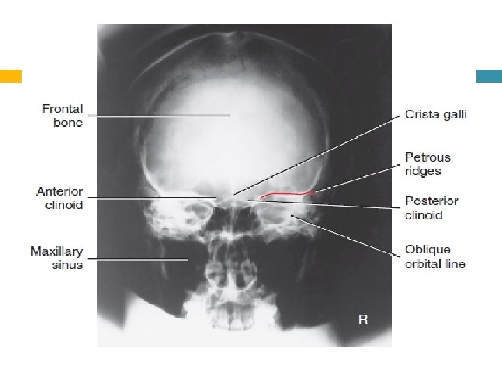
Evaluation Criteria Anatomy Demonstrated: • Frontal bone, crista galli, internal auditory canals, frontal and anterior ethmoid sinuses, petrous ridges, greater and lesser wings of sphenoid, and dorsum sellae are shown. .
Position: • No rotation is evident, as indicated by equal distance bilaterally from lateral orbital margin to lateral cortex of skull. • Petrous ridges fill the orbits and level of the supraorbital margin. • Posterior and anterior clinoids are visualized just superior to ethmoid sinuses. • Collimation to area of interest. Exposure: • Density (brightness) and contrast are sufficient to visualize frontal bone and surrounding bony structures. • Sharp bony margins indicate no motion
Occipito-frontal caudal angulation: 10, 15 and 20 degrees Occipito-frontal projections can be employed with different degrees of beam angulations. The choice of projection will depend upon departmental protocol and the anatomy that needs to be demonstrated
Patient Position Remove all metallic or plastic objects from the patient’s head and neck. Take radiograph with patient in the erect or prone position.
Part Position • Rest patient’s nose and forehead against table/imaging device surface. • Flex neck as needed to align OML perpendicular to IR. • Align MS P perpendicular to midline of the grid or table/imaging surface to prevent head rotation or tilt. • Center IR to CR
Direction and centring of the X-ray beam ü ü ü The central ray is directed perpendicular to the Bucky along the median sagittal plane. A collimation field should be set to include the vertex of the skull superiorly, the region immediately below the base of the occipital bone inferiorly, and the lateral skin margins. It is important to ensure that the tube is centred to the middle of the Bucky.
Occipito-frontal caudal angulation: Ø Ø 10, 15 and 20 degrees The technique used for these three projections is similar to that employed for the occipito-frontal projection, except that a caudal angulation is applied. The degree of angulation will depend on the technique, e. g. for an OF 20°↓ projection, a 20 degree caudal angulation will be employed.
CONT Ø Ø Ensure that the central ray is always centred to the middle of the Bucky once the tube angulation has been applied and not before. The degree of beam angulations can be evaluated from an assessment of the position of the petrous ridges within the orbit
– Occipito-frontal 0 ° : Ø the petrous ridges should be Ø completely superimposed within the orbit, with their upper borders coincident with the upper third of the orbit. .
– OF 10° ↓: the petrous ridges appear in the middle third of the orbit.
– OF 15° ↓: the petrous ridges appear in the lower third of the orbit.
– OF 20° ↓: the petrous ridges appear just below the inferior orbital margin
Common faults and remedies: Rotation: ensure that the patient’s head is straight immediately before the exposure is made. Incorrect beam angulation: it is worth remembering that greater beam angulations will result in the petrous ridges appearing further down the orbit.
LATERAL POSITION—RIGHT OR LEFT LATERAL Clinical Indications v Skull fractures, neoplastic processes, and Paget’s disease v Trauma routine A horizontal beam projection.
Technical Factors Ø Ø Ø Minimum SID— 40 inches (102 cm) IR size— 24 × 30 cm (10 × 12 inches), crosswise Grid Shielding Shield radiosensitive tissues outside region of interest. Recommended Collimation Collimate on four sides to anatomy of interest. Respiration Suspend respiration during exposure.
Patient Position Remove all metal, plastic, or other removable objects from patient’s head. Take radiograph with patient in the erect or recumbent semiprone position.
Part Position • Place the head in a true lateral position, with the side of interest closest to IR and the patient’s body in a semiprone position as needed for comfort. Align MS P parallel to IR, ensuring no rotation or tilt. • Align IPL perpendicular to IR, ensuring no tilt of head • Adjust neck flexion to align IOML perpendicular to front edge of IR. (GAL is parallel to front edge of IR. )
CR • Center to a point 2 inches (5 cm) superior to EAM
Right lateral—recumbent
Evaluation Criteria Anatomy. Demonstrated: • Entire cranium visualized and superimposed parietal bones of cranium. The entire sella turcica, including anterior and posterior clinoid processes and dorsum sellae, is also demonstrated.
Position: • No rotation or tilt of the cranium is evident. • Rotation is evident by anterior and posterior separation of symmetric vertical bilateral structures such as the EAM, mandibular rami, and greater wings of the sphenoid. • Tilt is evident by superior and inferior separation of symmetric horizontal structures such as the orbital roofs (plates) and greater wings of sphenoid.
(Submento-vertical) SMV PROJECTION Patient Position Remove all metal, plastic, and other removable objects from patient’s head. Take radiograph with patient in an erect or supine position. The erect position, which is easier for the patient, may be done with an erect table or an upright imaging device
Part Position Raise patient’s chin and hyperextend the neck if possible until IOML is parallel to IR Rest patient’s head on vertex. Supine With patient in the supine position, extend patient’s head over end of table, and support grid cassette and head as shown, keeping IOML parallel to IR and perpendicular to CR.
CONTS Erect If patient is unable to extend the neck sufficiently, compensate by angling CR to remain perpendicular to IOML. Depending on the equipment used, IR also may be angled to maintain the perpendicular relationship with CR (e. g. , with an adjustable upright imaging device). This position is very uncomfortable for patients in the erect or the supine position; perform it as quickly as possible
CR • CR is perpendicular to infraorbitomeatal line. • Center 1 1/2 inch (4 cm) inferior to mandibular symphysis, or midway between the gonions. • Center IR to CR
SMV.
Evaluation Criteria Anatomy Demonstrated: • Foramen ovale and spinosum, mandible, sphenoid and posterior ethmoid sinuses, mastoid processes, petrous ridges, hard palate, foramen magnum, and occipital bone are demonstrated
Position: • Correct extension of neck and relationship between IOML and CR as indicated by mandibular mentum anterior to the ethmoid sinuses. • No rotation evidenced by the MSP parallel to edge of IR. • No tilt evidenced by equal distance between mandibular ramus and lateral cranial cortex. . • Collimation to area of interest. .
AP AXIAL PROJECTION TOWNE METHOD Clinical Indications Ø Skull fractures (medial and lateral displacement), neoplastic processes, and Paget’s disease Ø Technical Factors Ø Minimum SID— 40 inches (102 cm) Ø IR size— 24 × 30 cm (10 × 12 inches), Ø lengthwise Ø Grid
Patient Position Remove all metal, plastic, or other removable objects from the patient’s head. Take radiograph with the patient in the erect or supine position. .
Part Position • Depress chin, bringing OML perpendicular to IR. For patients unable to flex the neck to this extent, align IOML perpendicular to IR. Add radiolucent support under the head if needed • Ensure that no head rotation or tilt exists. • Ensure that the vertex of the skull is within collimation field
CR Angle CR 30° caudad to OML, or 37° caudad to IOML Center at MSP 2 1/2 inches (6. 5 cm) above the glabella to pass through the foramen magnum at the level of the base of the occiput.
AP axial. Supine—AP axial. CR 30° to OML or 37° to IOML
1. 2. 3. 4. Evaluation Criteria Occipital bone, petrous pyramids, and foramen magnum are demonstrated with the dorsum sellae and posterior clinoids visualized in the shadow of the foramen magnum.
SKULL RADIOLOGY FACIAL BONES