Photonics in ONF Core and some TAPI Nigel
 Nigel Davis (Ciena) 20180613")

 has an upper and lower frequency (or")


 SMCs ROADM ROADM SMC SMCG")


 SMCGs and part a direct")


 OTSi. A n OTSi")


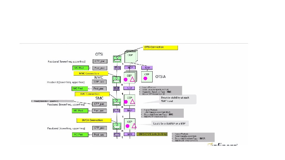


 he hin t t")


: Forwarding, Termination and Topology Network Showing layers From TR-512. 2")


- Slides: 61
Photonics in ONF Core (and some TAPI) Nigel Davis (Ciena) 20180613
Terminology nightmare!! • It can be argued that the NMC goes into the laser and receive device substrate • NMC can be any chunk of SMC/TMC depending upon the SMC/TMC definition • So figure needs to be drawn carefully • OMS/OTS are actually MC… • OTS Fiber. MC (FMC) and OMS Amplified. MC (AMC) • This is the best I can do for now • All levels should have MC, MCGO and MCA equivalents • Would be ideal to have the same terms for each • O and A could probably be improved a bit (I removed the hyphen btw) • OTSi really should be NMC • Levels are (using terminology above) • • FMC, FMCG, FMCO, FMCA AMC, AMCG, AMCO, AMCA TMC, TMCG, TMCO, TMCA NMC, NMCG, NMCO, NMCA guardband NMC • NMC is the MC between transponders (i. e. the greatest extent of media before we exit to another “layer”) NMC • Service Media Channel Transit Media Channel (TMC)? ? guardband • SMC is not really Service related…. It is a predefined Transit across several ROADMs Transit Media Channel
Band discussion • A Media Channel (MC) has an upper and lower frequency (or not so sensibly, centre and width) and “occupies” all frequencies between those bounds • A MC may has a guard band… the Service Media Channel (SMC) has a guard band • SMC is connected between two ROADM nodes passing through intervening ROADM nodes • An SMC is created in the context of an SMCA (SMCG+O) that defines the ROADM node span and path of the SMCs within it. • An SMCA passes across multiple (serial) OMSAs (OMSG+O where OMSG = L and C Band) and only one SMCA can pass between the same points over the same route (i. e. all SMCs that pass between the same points over the same OTS route must be in the same SMCA) • OTSi. A is a group of OTSis + Overhead where each OTSi must pass the same way through the same ROADM nodes between the same ROADM nodes. Hence an OTSi. A may use one SMCA across the entire span or and may use a series of single SMCAs. OTSi. G (NMCG) A group of media channels with or without light No OTSi. G (NMCG) OTSi (NMC) No SMCG Not allowed SMCG A group of media channels with or without light OSC NMC/OTSi Fiber OTS (FMCA) OMS (AMCA) OMS-C OMS-L No Band NMC Source off Unallocated (No SMC) SMC with no specified channels Unallocated NMC Source off No Band NMC Source on Unallocated No Band SMC
Overlay animation Fiber OSC-OTSi OSC OTSi. G-O OMS-O OTS-O SMC OTSi. A/OTU ODU SMCG OTS Need to add SMCA (i. e. with overhead) OMS OTSi. G OTSi. A NE
Decisions • Layer. Protocol • • • PHOTONIC_MEDIA with qualifier? Keep qualifier aligned with ITU-T naming or improve naming? Keep (reluctantly – my strong preference is to rationalize it but that is a long climb) OTSi. A should be PHOTONIC_MEDIA with qualifier of OTSi. A and NOT OTSi. A? PHOTONIC_MEDIA • Directionality • Bidirectional TPs accept where the is genuine unidirectional asymmetry (as we do with all other layers) • • Reduces complex coupling relationships and keeps transactional units together as single instance Simplifies provisioning and discovery • L&C in OMS and OTS • Keep L&C together in same LTPs (and if any other bands happen to be three do the same) • • • Reduces complexity There is not connectivity reason to separate Reduces instances Keeps transactional units together as single instances Where there is one, e. g. L, only by design, use spec to dictate this Where there is L and C opportunity with only one equipped, use spec to highlight the option and allow the property group to be added as appropriate • • • I. e. an LTP can have more LPs added on-the-fly… this is like “this layer active” in MTNM This could be done by making all properties visible and then setting them to unequipped/null This could be done by simply “cutting over” to another LTP whilst preserving traffic (same behaviour as a traffic card upgrade – have done this in solutions since the mid-90 s) • SMC • • Form with and FC Monitored as a soectrum • SMCG • • Form with an FC SMCGs are not monitored directly but the active OTSi. GAs are monitores
Valid: OTSi. G fills SMC ROADM ROADM SMCG ROADM
Valid: OTSi. G does not fill SMC ROADM ROADM SMCG ROADM
Valid: OTSi. G takes part of the two SMC in an SMCG ROADM SMC SMCG ROADM
Valid: OTSi. G takes part of two of the many SMCs in an SMCG ROADM ROADM SMC SMCG ROADM
Valid: OTSi. G transits two (serial) SMCs ROADM ROADM SMC SMCG
Valid: OTSi. G transits serial SMCs that are asymmetric ROADM SMC ROADM SMC SMCG
NOT VALID: OTSi. G transits serial SMCs that are asymmetric ROADM SMCG ROADM SMC ROADM SMC SMCG Even though the SMCs transit the same route between the same ROADMs they are in different SMCGs… BUT… because the two SMCs go between the same two ROADMs across the same fibres etc should they ALWAYS be in the same SMCG!! So the SMCG configuration is invalid
NOT VALID: An SMC cannot be in a SMCG that does not match its extent ROADM ROADM SMC SMCG SMC
Valid: SMCGs from a specific ROADM exiting on a specific port may have different extents ROADM SMCG ROADM SMC SMCG
NOT VALID: Part of OTSi. G transits two (serial) SMCGs and part a direct SMCG ROADM SMC ROADM SMC SMCG
Valid: Two separate OTSi. Gs go between the same to ROADM devices but via different SMCGs SMCG ROADM SMC ROADM SMC SMCG
OAM Proposal • Encapsulated in the termination • Measurement aspect of termination • Overhead aspect of the termination • Separated into OAM • Interpretation of measurements • A representation of the measurement span Concerns • Number of lock-step coupled instances that are indirectly associated in the model (seem to be compositional but modelled as very separate) • Number of opaquely identified parts (UUIDs) • Simple case in photonics becomes very complex in the model
Comparison • C&L split = + 2/4 for each port & more complex SMCG formation • Uni split = x 2 for whole model & interrelationship associations • OAM separation = x >2 for all entities & interrelationship association
Colour scheme nightmare ODU 2 CTP
Core NO SMCG OTSi n Mid span End of span OTU 4/ODU 4 1 OTSi n OTSi OMS OMS OTS OTS n OTSi OMS 1 OMS OTS OS OTU/ODU (Large) n n OTSi. A n n OTSi. A OMS OTSi. A n OTSi. A OTSi OMS OMS OTS OTS n OMS m OS OTS OS OTU/ODU (Large) OTSi. A n n OTSi n OMS OTSi. A OS OTSi. A OTSi OMS OMS OTS OTS n n OTSi. A Simplified OTSi. A OTSi OMS m m OTS OS
Core With SMCG OTSi n n SMC OMS 1 OTS OS Mid span End of span OTU 4/ODU 4 1 OTSi SMC SMC OMS OMS OTS OTS n OTS OS OTU/ODU (Large) OTSi. A n n OTSi 1 n n SMC-G SMCG OMS OTSi. A n OTSi. A OTSi SMC-G SMC SMC OMS OMS OTS OTS m OS OTS OS OTU/ODU (Large) n OTSi. A n OTSi n 1 1 n SMC-G SMC OMS OTSi. A SMCG Simplified OS OTSi. A OTSi SMC-G n OTSi. A OTSi SMC-G SMC SMC OMS OMS OTS OTS m m OTS OS
Core with SMCG Mid span End of span OTU/ODU (Large) OTSi. A n OTSi n 1 1 OMS OTS SMCG Simplified OS OTSi. A n 1 n SMCG OMS OTSi n SMC-G SMC OTSi. A n SMCG Simplified 1 OTSi SMC-G SMC n OTSi. A OTSi SMC-G SMC OMS OMS OTS OTSi. A SMCG OMS OMS OTS OTS OTSi. A OMS OMS OTS OTS r e p s A OMS m OTS n e d i l s s u o i v e r p OTSi. A m OS OTU 4/ODU 4 1 m OTS OS OTU 4/ODU 4 OTSi. A n n OMS No SMC 1 OTSi. A 1 m OTS OS
Core SMCG alternative No t va OTSi. A n m n SMCG OMS 1 1 Mid span End of span e d i l s s u o i lid… v e r p r e p c s o A ns tra int so n. S MC Gt o. O OTU 4/ODU 4 SMCG Simplified n OTSi. A 1 OTSi. A SMCG OMS OMS OTS OTS OTSi. A m OTS OS OTU 4/ODU 4 OTSi. A n n n OMS 1 1 SMCG Alternative SMCG OTSi. A 1 SMCG OMS OMS OTS OTS OTSi. A OMS OMS OTS OTS m OTS OS OTU 4/ODU 4 OTSi. A n OMS n No SMC 1 OTSi. A 1 m OTS OS TSi A OMS OTS
Core with SMCG OTSi. A n 1 n SMCG OMS SMCG Simplified 1 n Mid span End of span OTU 4/ODU 4 1 OTSi. A SMCG OMS OMS OTS OTS OTSi. A SMCG OMS OMS OTS OTSi. A OMS OMS OTS OTS m OTS OS OTU 4/ODU 4 NMCA/OTSi. A n 1 n n TMCA/SMC(A) SMCG AMCA/OMS(A) OMS 1 1 OTSi. A n n m FMCA/OTS(A) OS OTS OS OTU 4/ODU 4 OTSi. A n n OMS No SMC 1 1 OTSi. A n OMS m OTS OS
Amplifier site showing Core model
LTP/LP spec enhancements • Allow for expression of arrangement of LPs using instances of “FC” in the LTP spec • Add “ports” to the LP • Allow LP spec to recurse so LPs are in LP • Allow more complex arrangements of Termination in LP spec
Amplifier site with overlaid FRUs showing spans LCon OMS Link Con OTS Link LIM
Amplifier site showing Core classes and physical structure FC FC OMS Link FC FC OTS Link Multi-Strand Span o Strand o R 1 -13 -8 o Strand o T 1 -13 -5 r complex Strand 1 -13 -7 t complex 1 -13 -6 LIM r complex 1 -2 -6 Strand t t 1 -2 -5 complex 1 -2 -7 r 1 -2 -8 LIM
Amplifier site showing TAPI classes and physical structure Con LCon OMS Link Con OTS Link Multi-Strand Span o Strand o R 1 -13 -8 o Strand o T 1 -13 -5 r complex Strand 1 -13 -7 t complex 1 -13 -6 LIM r complex 1 -2 -6 Strand t t 1 -2 -5 complex 1 -2 -7 r 1 -2 -8 LIM
Layer. Protocol substructuring OTS CEP Overhead Photonic Tx Photonic Params Rx Photonic Params Overhead Frame Overhead Parameters L-Band Local Measures Tx Photonic Params Rx Photonic Params C-Band Local Measures Tx Photonic Params Rx Photonic Params L-Band Conveyed Parameters Tx values Params Rx values Params C-Band Conveyed Parameters Tx values Params Rx values Params
Connection Substructuring Connection East-West Amp L-Band Input Params Output Params C-Band Input Params Output Params West-East Amp L-Band Input Params Output Params C-Band Input Params Output Params
Add-Drop Site showing core model OTSi. A and Band detail See next slide ROADM 2
Add-Drop Site showing OTSi. A detail (with excessive monitoring ) he hin t t i w n uatio velength n n e t t i gth a e full wa s sense n e l e v e a k so av er w d must h only ma though FC? p d d n n h to a TSi. A e Ba engt uatio Need Hence th ol. Atten ed wavel s of the O. r C n band cont provisio e OTSi F a il th deta ntext of ld be in u o the c this sho e mayb ROADM 2
Add-Drop Site showing core model Con OMS Link Con OTS Link OTSi. A and Band detail See next slide LIM WSS ROADM 2 WSS LIM
Note that Band does NOT have an overhead capability (but can have measures that propagate to the dependent OTSi. As) LCon Note that Band SMC needs OTSi. A to be unidirectional tree!! Link Add-Drop Site showing OTSi. A detail (with excessive monitoring ) Note OMS, OTS and OTSi. A are bidirectional because of the overhead. OTSi. A really represents the Information Channel. LCon Band Link Con OMS Link WSS ROADM 2
“Aggregated” terminal site with no band measures
“Aggregated” terminal site with overlaid FRUs Con OTSi. A Link showing spans (and no band measures) Con Band Link Con OMS Link PXFP Con OTS Link CMD WSS LIM
Con LCon OTSi. A Link Con NEP Connection. Has. Lower. Level. Connections NEP Connection. Has. Lower. Level. Connections Connection. Has. Lower. Level. Connections NEP LCon Band Link NEP Con OMS Link. Terminates. On. NEP Link CEPHas. Client. NEPs P 20 ROADM 1 Con NEP Connection. Supports. Link Conn. Terminates. On. SEP NEP P 20 ROADM 2 Con OTS Link CEPHas. Server. NEP NEP Multi-Strand Span t Strand 1 -4 -5 r Strand r complex 1 -84 -7 1 -84 -90 t r complex 1 -84 -8 PXFP t 1 -84 -89 CMD Strand r complex t 1 -10 -19 1 -10 -22 t r complex 1 -10 -20 1 -10 -21 WSS Strand r complex 1 -13 -6 Strand t t o Strand o 1 -13 -5 complex 1 -13 -7 r 1 -13 -8 LIM R 1 -13 -8 o Strand o T 1 -13 -5 r complex Strand 1 -13 -7 t complex 1 -13 -6 LIM Strand r complex t 1 -10 -21 1 -10 -4 t r complex 1 -10 -22 1 -10 -3 WSS Strand r complex 1 -3 -3 Strand t Strand 1 -3 -22 complex 1 -3 -4 t r 1 -3 -21 WSS r complex 1 -2 -6 Strand t t 1 -2 -5 complex 1 -2 -7 r 1 -2 -8 LIM
Con LCon OTSi. A Con NEP Connection. Has. Lower. Level. Connections OTSi. A Link NEP CEPHas. Client. NEPs P 20 ROADM 1 Con NEP Con OMS Link. Terminates. On. NEP Link NEP Connection. Supports. Link Conn. Terminates. On. SEP NEP P 20 ROADM 2 Con OTS Link CEPHas. Server. NEP NEP Multi-Strand Span t Strand 1 -4 -5 r Strand r complex 1 -84 -7 1 -84 -90 t r complex 1 -84 -8 PXFP t 1 -84 -89 CMD Strand r complex t 1 -10 -19 1 -10 -22 t r complex 1 -10 -20 1 -10 -21 WSS Strand r complex 1 -13 -6 Strand t t o Strand o 1 -13 -5 complex 1 -13 -7 r 1 -13 -8 LIM R 1 -13 -8 o Strand o T 1 -13 -5 r complex Strand 1 -13 -7 t complex 1 -13 -6 LIM Strand r complex t 1 -10 -21 1 -10 -4 t r complex 1 -10 -22 1 -10 -3 WSS Strand r complex 1 -3 -3 Strand t Strand 1 -3 -22 complex 1 -3 -4 t r 1 -3 -21 WSS r complex 1 -2 -6 Strand t t 1 -2 -5 complex 1 -2 -7 r 1 -2 -8 LIM
Con LCon OTSi. A Con NEP Connection. Has. Lower. Level. Connections OTSi. A Link NEP CEPHas. Client. NEPs P 20 ROADM 1 Con NEP Con OMS Link. Terminates. On. NEP Link NEP Connection. Supports. Link Conn. Terminates. On. SEP NEP P 20 ROADM 2 Con OTS Link CEPHas. Server. NEP NEP Multi-Strand Span t Strand 1 -4 -5 r Strand r complex 1 -84 -7 1 -84 -90 t r complex 1 -84 -8 PXFP t 1 -84 -89 CMD Strand r complex t 1 -10 -19 1 -10 -22 t r complex 1 -10 -20 1 -10 -21 WSS Strand r complex 1 -13 -6 Strand t t o Strand o 1 -13 -5 complex 1 -13 -7 r 1 -13 -8 LIM R 1 -13 -8 o Strand o T 1 -13 -5 r complex Strand 1 -13 -7 t complex 1 -13 -6 LIM Strand r complex t 1 -10 -21 1 -10 -4 t r complex 1 -10 -22 1 -10 -3 WSS Strand r complex 1 -3 -3 Strand t Strand 1 -3 -22 complex 1 -3 -4 t r 1 -3 -21 WSS r complex 1 -2 -6 Strand t t 1 -2 -5 complex 1 -2 -7 r 1 -2 -8 LIM
Con LCon OTSi. A Con NEP Connection. Has. Lower. Level. Connections OTSi. A Link NEP CEPHas. Client. NEPs P 20 ROADM 1 LCon OMS Link. Terminates. On. NEP Link NEP TCon OTS Link NEP Connection. Supports. Link Conn. Terminates. On. SEP CEPHas. Server. NEP Multi-Strand Span t Strand 1 -4 -5 r Strand r complex 1 -84 -7 1 -84 -90 t r complex 1 -84 -8 PXFP t 1 -84 -89 CMD Strand r complex t 1 -10 -19 1 -10 -22 t r complex 1 -10 -20 1 -10 -21 WSS Strand r complex 1 -13 -6 Strand t t o Strand o 1 -13 -5 complex 1 -13 -7 r 1 -13 -8 LIM ILA R 1 -13 -8 o Strand o T 1 -13 -5 r complex 1 -13 -7 Strand 1 -10 -21 t complex 1 -13 -6 LIM complex 1 -2 -6 Strand 1 -10 -22 r t t 1 -2 -5 complex 1 -2 -7 r 1 -2 -8 LIM
Con LCon OTSi. A Con NEP Connection. Has. Lower. Level. Connections OTSi. A Link NEP Con NEP CEPHas. Client. NEPs P 20 ROADM 1 Connection. Supports. Link Conn. Terminates. On. SEP OTS Link CEPHas. Server. NEP NEP NEP Multi-Strand Span t Strand 1 -4 -5 r Strand r complex 1 -84 -7 1 -84 -90 t r complex 1 -84 -8 PXFP t 1 -84 -89 CMD Strand r complex t 1 -10 -19 1 -10 -22 t r complex 1 -10 -20 1 -10 -21 WSS Strand r complex 1 -13 -6 Strand t t o Strand o 1 -13 -5 complex 1 -13 -7 r 1 -13 -8 LIM ILA R 1 -13 -8 o Strand o T 1 -13 -5 r complex 1 -13 -7 Strand 1 -10 -21 t complex 1 -13 -6 LIM complex 1 -2 -6 Strand 1 -10 -22 r t t 1 -2 -5 complex 1 -2 -7 r 1 -2 -8 LIM
Con LCon OTSi. A Con NEP Connection. Has. Lower. Level. Connections OTSi. A Link NEP Con Link. Terminates. On. NEP CEPHas. Client. NEPs P 20 ROADM 1 NEP Connection. Supports. Link Conn. Terminates. On. SEP Con OTS Link CEPHas. Server. NEP NEP Multi-Strand Span t Strand 1 -4 -5 r Strand r complex 1 -84 -7 1 -84 -90 t r complex 1 -84 -8 PXFP t 1 -84 -89 CMD Strand r complex t 1 -10 -19 1 -10 -22 t r complex 1 -10 -20 1 -10 -21 WSS Strand r complex 1 -13 -6 Strand t t o Strand o 1 -13 -5 complex 1 -13 -7 r 1 -13 -8 LIM ILA R 1 -13 -8 o Strand o T 1 -13 -5 r complex 1 -13 -7 Strand 1 -10 -21 t complex 1 -13 -6 LIM complex 1 -2 -6 Strand 1 -10 -22 r t t 1 -2 -5 complex 1 -2 -7 r 1 -2 -8 LIM
Layer. Protocol substructuring May be broken down into bands etc.
Layer. Protocol substructuring OMS CEP Overhead Frame Overhead Parameters Local Measures L-Band Tx Photonic Params Rx Photonic Params Conveyed Parameters L-Band Tx values Rx values Params C-Band Tx values Params Rx values Params
Layer. Protocol substructuring Network. Band CEP Tx. Bands Rx. Bands
“Disaggregated” terminal site
“Disaggregated” Transponder
Canonical network model (virtualized/functional): Forwarding, Termination and Topology Network Showing layers From TR-512. 2 Network Device OR Opaque Network Model for any networking, for any transport network technology, with any degree of virtualization, at any scale, at any abstraction and in any interrelated view. See slide notes
ONF TAPI – Connectivity model
Underpinning Photonic model • The ONF Photonic model is a model of media and channels • Media is essentially “omni-directional” with some uni-directional elements • In the ONF core, the model uses primarily Forwarding. Constructs (FC). The FC • Is used to represent Enabled Constrained Potential for Forwarding • Is used for any layer technology (digital packet, digital circuit, analogue) • Represents, as necessary, a complex channel arrangement with switches and filters • Forwarding capability is understood through the intersection of a series of pass characteristics along with characteristic of degradation • In the case of photonics these are band pass characteristics, attenuation etc • The channel is modelled in abstract with access to the underlying detail • The model of underlying detail was developed first then abstracted • Photonic/Electronic conversion is modelled as a Logical. Termination. Point (LTP) composed of Layer. Protocol (LP) units • DSP accounted for in the formation of an information channel represented by an FC that passes between source and sync tuning elements • The Dynamic aspects of forwarding/termination are captured via properties and settings of the forwarding/termination elements • Invariant aspects are captured via metadata structure (ONF Specifications) • In TAPI: • The FC becomes the Connection • The LTP becomes a combination of Connection. End. Point (CEP) and Node. Edge. Point (NEP)
Some model fragments in ONF Core pictorial form Control Termination Forwarding Encapsulated Termination
EDFA Node/FRU Encapsulated termination and Forwarding Node/FRU Connector Pin Abstracted amplifier Detail contained in subordinate FCs and LTPs
Two network cases
The model of Monitors and Overhead • Monitoring is “non-intrusive” taking a small sample of the signal, either full aggregate (broadband) or narrow band (inc channel) • The Overhead is similar to a traditional layered protocol with OTSi. G-O carried by OMS-O carried by OTS-O carried over a dedicated OTSi • This layering is represented as a stack of terminations • The Overhead carries information about the photonic signals at various intermediate and terminal point including measures from monitors and trace details • The Overhead is bidirectional • It is considered vital that the relationship between the overhead information, the measures and traces, and the points to which the information relates is simplified to a degree similar to that of traditional SONET/SDH NEs • A hybrid model results from this consideration where the terminations of the overhead drive the essential model shape but where the photonic signal is considered in one layer PHOTONIC_MEDIA (and hence the model is flat). • The photonic forwarding information is grouped with the measures and overhead • The groupings use the Core LTPs (TAPI CEs) where there is an Overhead termination • The grouping uses a Core FC (TAPI Connection) where the emphasis is the channel
Overhead considerations
A-L A-M B-L = = Not Possible J F C Exclusive due to clashes on Red and Green (highlighted with the ellipses) Band Assuming band split and merge. OTSi L A G I K B D E M H
A-L A-M B-L = = Not possible = Not Possible Assuming band split but no merge. J F C Band OTSi L A G I K B D E M H
A-L A-M B-L = = Not possible = = Not Possible Assuming band split but no merge. J F C Band OTSi L A G I K B D E M H
A-L A-M B-L = = Not possible = = Not Possible Assuming band routed. J F C Band OTSi L A G I K B D E M H