Reference TAPI Photonic Model Weekly TAPIIMP Call Participants
- Slides: 29
Reference TAPI Photonic Model Weekly TAPI-IMP Call Participants June/July/Aug/Sept/Oct 2018
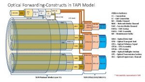
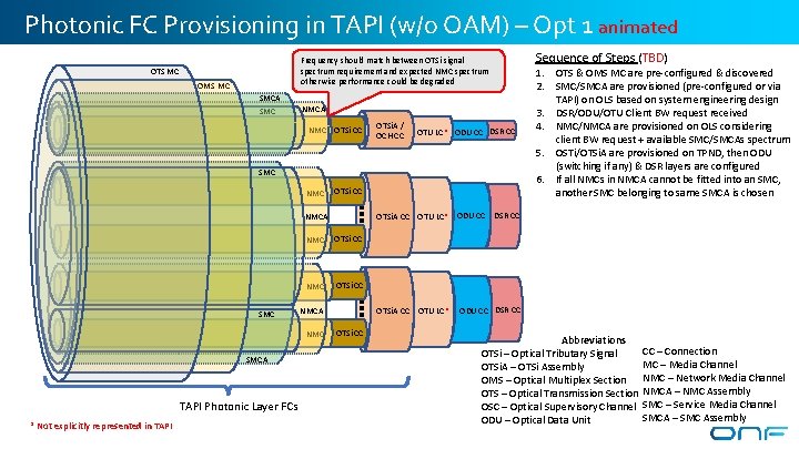
Photonic FC Provisioning in TAPI (w/o OAM) – Opt 1 animated Sequence of Steps (TBD) Frequency should match between OTSi signal spectrum requirement and expected NMC spectrum otherwise performance could be degraded OTS MC OMS MC SMCA SMC NMCA NMC OTSi CC OTSi. A / OCH CC OTU LC* ODU CC DSR CC SMC NMC OTSi CC OTSi. A CC OTU LC* ODU CC NMCA SMC NMC OTSi CC NMCA NMC SMCA TAPI Photonic Layer FCs * Not explicitly represented in TAPI OTSi. A CC OTU LC* OTSi CC 1. OTS & OMS MC are pre-configured & discovered 2. SMC/SMCA are provisioned (pre-configured or via TAPI) on OLS based on system engineering design 3. DSR/ODU/OTU Client BW request received 4. NMC/NMCA are provisioned on OLS considering client BW request + available SMC/SMCAs spectrum 5. OSTi/OTSi. A are provisioned on TPND, then ODU (switching if any) & DSR layers are configured 6. If all NMCs in NMCA cannot be fitted into an SMC, another SMC belonging to same SMCA is chosen DSR CC ODU CC DSR CC Abbreviations OTSi – Optical Tributary Signal OTSi. A – OTSi Assembly OMS – Optical Multiplex Section OTS – Optical Transmission Section OSC – Optical Supervisory Channel ODU – Optical Data Unit CC – Connection MC – Media Channel NMC – Network Media Channel NMCA – NMC Assembly SMC – Service Media Channel SMCA – SMC Assembly
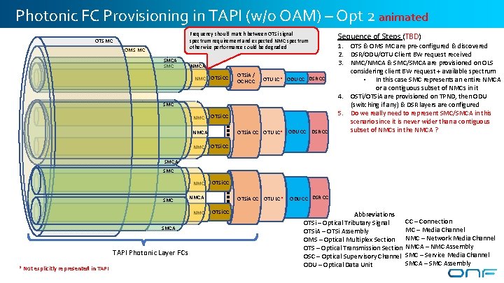
Photonic FC Provisioning in TAPI (w/o OAM) – Opt 2 animated Frequency should match between OTSi signal spectrum requirement and expected NMC spectrum otherwise performance could be degraded OTS MC OMS MC SMCA SMC Sequence of Steps (TBD) NMCA NMC OTSi CC OTSi. A / OCH CC OTU LC* ODU CC DSR CC SMC NMC OTSi CC OTSi. A CC OTU LC* ODU CC NMCA NMC OTSi CC DSR CC 1. OTS & OMS MC are pre-configured & discovered 2. DSR/ODU/OTU Client BW request received 3. NMC/NMCA & SMC/SMCA are provisioned on OLS considering client BW request + available spectrum • In this case SMC represents an entire NMCA or a contiguous subset of NMCs in it 4. OSTi/OTSi. A are provisioned on TPND, then ODU (switching if any) & DSR layers are configured 5. Do we really need to represent SMC/SMCA in this scenario since it is never wider than a contiguous subset of NMCs in the NMCA ? SMCA SMC NMCA NMC SMCA TAPI Photonic Layer FCs * Not explicitly represented in TAPI OTSi. A CC OTU LC* OTSi CC ODU CC DSR CC Abbreviations OTSi – Optical Tributary Signal OTSi. A – OTSi Assembly OMS – Optical Multiplex Section OTS – Optical Transmission Section OSC – Optical Supervisory Channel ODU – Optical Data Unit CC – Connection MC – Media Channel NMC – Network Media Channel NMCA – NMC Assembly SMC – Service Media Channel SMCA – SMC Assembly
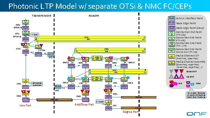
Photonic LTP Model w/ separate OTSi & NMC FC/CEPs TRANSPONDER ODU (ODUCn) OTU (OTUCn) ROADM Service Interface Point Node Edge Point 1 1. . c Node Edge Point Group Connection End Point (TTP only) c ~Flex. O Connection End Point OTSi. A OTSi (CTP only) 1. . r Connection End Point r OTSi s*n 1: 1 (TTP + CTP) 1: 1 Connection End Point NMCA NMC OTSi. A (Inverse mux CTP only) 1: 1 OTSi NMCA N Media Channel CEP NMCA NMC r NMC n {lower. Freq, upper. Freq} r` n` NMC N` Media Channel Assembly NMCA [{lower. Freq, upper. Freq}, . . ] q` q SMCA SMC 1: 1 SMCA Not explicitly modeled represented SMC OMS 1: 1 SMC S s SMC S` Up MEP SMCA MIP p` 1 1 OMS Link Line Port s` p OMS 1 SMCA SMC Down MEP 1: 1 Add/Drop Port OMS Link C/L bands 1. . 2 OTS Link Degree Port OPM Non Intrusive Monitoring No Specific OAM signaling Optical Power Monitoring
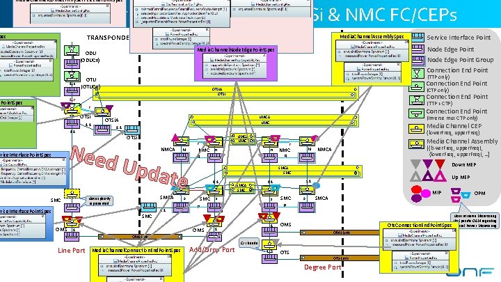
Media. Channel. Connectivity. Service. End. Point. Spec Photonic LTP Model w/ separate OTSi & NMC FC/CEPs TRANSPONDER pec 1 ODU (ODUCn) 1. . c OTU (OTUCn) ROADM Media. Channel. Assembly. Spec Node Edge Point Media. Channel. Node. Edge. Point. Spec Node Edge Point Group Connection End Point (TTP only) Connection End Point OTSi. A OTSi (CTP only) Connection End Point 1. . r d. Point. Spec (TTP + CTP) r 1: 1 OTSi NMCA Upda N {lower. Freq, upper. Freq} NMC n te SMC S SMCA SMC Media. Channel. Connection. End. Point. Spec [{lower. Freq, upper. Freq}, . . ] NMCA Down MEP s s` Up MEP 1: 1 SMC S` MIP SMCA OPM p` p 1 1 Add/Drop Port Non Intrusive Monitoring No Specific OAM signaling Ots. Connection. End. Point. Spec Optical Power Monitoring OMS Link Line Port N` q` 1: 1 OMS 1 NMC SMCA SMC 1: 1 Media Channel Assembly r n` q SMCA SMC OMS Media Channel CEP NMCA NMC r Not explicitly modeled represented rvice. Interface. Point. Spec (Inverse mux CTP only) 1: 1 Need SMC Connection End Point NMCA NMC OTSi. A 1: 1 rvice. Interface. Point. Spec Service Interface Point C/L bands 1. . 2 OTS Link Degree Port
Use Cases of NMC/SMC mappings 6
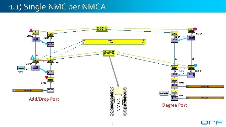
1. 1) Single NMC per NMCA 1 1 NMC SMCA SMC 1: 1 1 S 1 1: 1 SMC 1: 1 1 SMCA p OMS 1 OMS Link 7 guardband Add/Drop Port NMC-1 OMS Link guardband PHTN NMCA SMC 1 SMCA 1 NMC 1 C/L bands 1. . 2 OTS Degree Port OTS Link
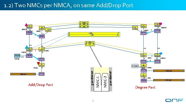
1. 2) Two NMCs per NMCA, on same Add/Drop Port NMCA NMC NMCA 1 1 1 2 NMC 1 NMC SMCA SMC 2 SMCA SMC 1: 1 SMCA 1 1 1: 1 SMC 1: 1 1 SMCA p C/L bands 1 8 guardband Add/Drop Port NMC-2 OMS Link 1. . 2 NMC-1 OMS guardband PHTN S NMCA OMS Link 1 OTS Degree Port OTS Link
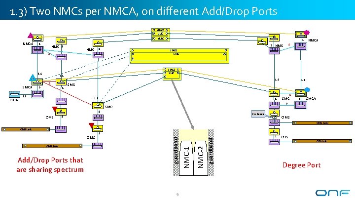
1. 3) Two NMCs per NMCA, on different Add/Drop Ports NMCA NMC NMCA 1 NMC 1 SMCA PHTN 1: 1 2 1 1: 1 SMC 1: 1 1 SMCA p SMC 1 OMS NMCA SMC 1: 1 S 1 NMC SMCA SMC 2 1: 1 1 2 C/L bands 1 1. . 2 OMS Link 9 guardband NMC-2 Add/Drop Ports that are sharing spectrum NMC-1 OMS Link 1 guardband OMS 1 OTS Link Degree Port
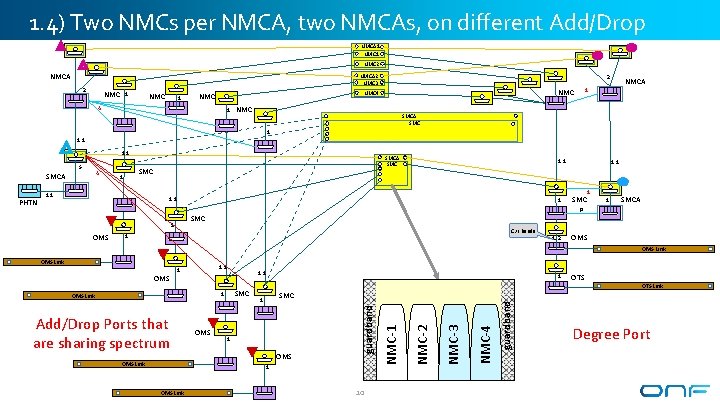
1. 4) Two NMCs per NMCA, two NMCAs, on different Add/Drop Ports NMCA 1 NMC 2 NMCA 2 NMC 3 2 NMC 1 2 NMC 4 1 NMCA 1 SMCA SMC 1 1: 1 S 4 SMCA PHTN SMCA SMC 1 1: 1 SMC 1 1 SMCA p SMC 1 OMS C/L bands 1 1. . 2 OMS Link 1: 1 OMS Link 10 guardband OMS 1 NMC-4 Add/Drop Ports that are sharing spectrum OTS Link SMC NMC-3 SMC 1 OMS Link 1 NMC-2 1 NMC-1 OMS guardband OMS Link Degree Port
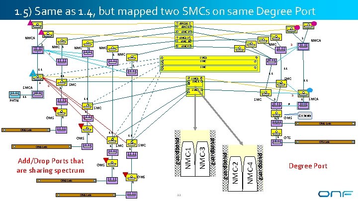
1. 5) Same as 1. 4, but mapped two SMCs on same Degree Port NMCA 1 NMC 2 NMCA 2 NMC 3 2 NMC 1 2 NMC 4 1 NMC SMCA SMC 1: 1 4 SMCA PHTN SMCA SMC 1 1: 1 SMC 2 1: 1 SMC 1: 1 2 2 1 SMCA p SMC 1 OMS NMCA 2 1 1. . 2 OMS C/L bands OMS Link 1: 1 1 OMS Link 11 guardband OMS Link OMS NMC-4 Add/Drop Ports that are sharing spectrum 1 NMC-2 1 OMS Link SMC 1 guardband SMC guardband 1: 1 NMC-3 1 NMC-1 OMS guardband OMS Link OTS Link Degree Port
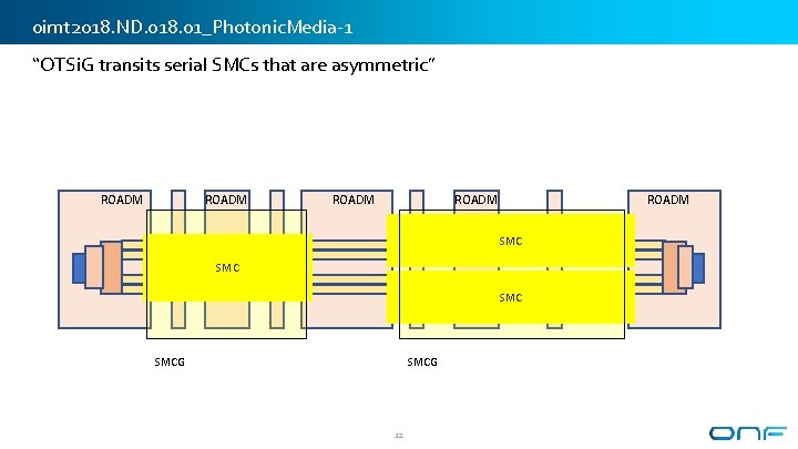
oimt 2018. ND. 018. 01_Photonic. Media-1 “OTSi. G transits serial SMCs that are asymmetric” ROADM SMC ROADM SMC SMCG 12
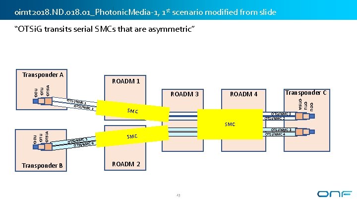
oimt 2018. ND. 018. 01_Photonic. Media-1, 1 st scenario modified from slide “OTSi. G transits serial SMCs that are asymmetric” Transponder A ODU OTSi. A ROADM 1 2 SMC ROADM 4 ODU OTSi. A SMC Transponder B C 3 OTSi/NM NMC 4 i/ S T O SMC ROADM 2 13 Transponder C OTSi/NMC 1 OTSi/NMC 2 OTSi/NMC 3 OTSi/NMC 4 ODU OTSi. A OTSi/NM C 1 OTSi/NM C ROADM 3
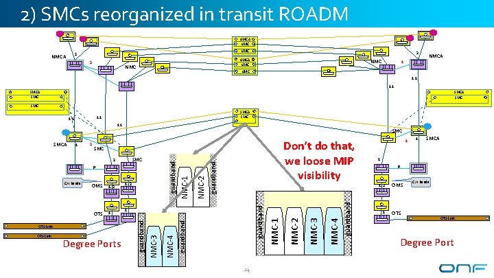
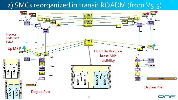
2) SMCs reorganized in transit ROADM NMCA NMC 2 NMCA 2 2 NMCA NMC NMC 1 NMCA NMC 1: 1 SMCA SMC 1: 1 SMC guardband NMC-4 NMC-2 guardband 14 NMC-3 Degree Ports NMC-2 OTS Link 1 NMC-1 OTS Link 1 1 SMCA 1 p 1. . 2 guardband 1 1. . 2 NMC-3 OTS 1. . 2 guardband OMS NMC-1 SMC 2 p C/L bands Don’t do that, we loose MIP visibility SMC guardband 2 guardband 1 NMC-4 SMCA 1 OMS OTS C/L bands OTS Link Degree Port
2) SMCs reorganized in transit ROADM (from V 5. 5) NMCA NMC 1 NMC 2 2 NMCA NMC 3 2 NMC 1 NMCA NMC 4 NMC 1: 1 Up. MEP SMC 1 Don’t do that, we loose MIP visibility 2 SMC NMC-3 NMC-2 OTS Link NMC-1 OTS 1 Degree Port 15 1 SMCA 1 p 1. . 2 guardband OMS 1. . 2 1 guardband NMC-2 NMC-4 NMC-1 NMC-3 guardband p guardband SMCA SMC 1: 1 NMC-4 Previous node has 2 SMCA 1 OMS OTS C/L bands OTS Link Degree Port
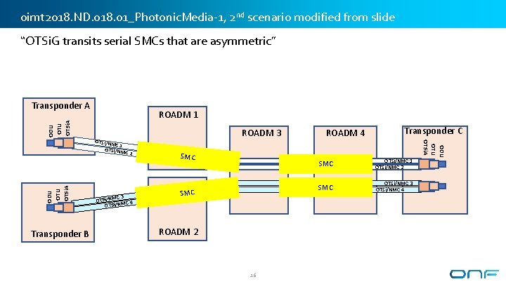
oimt 2018. ND. 018. 01_Photonic. Media-1, 2 nd scenario modified from slide “OTSi. G transits serial SMCs that are asymmetric” Transponder A ODU OTSi. A ROADM 1 ODU OTSi. A C 3 OTSi/NM NMC 4 i/ S T O SMC ROADM 2 16 Transponder C SMC OTSi/NMC 1 OTSi/NMC 2 SMC OTSi/NMC 3 OTSi/NMC 4 Transponder B 2 ROADM 4 ODU OTSi. A OTSi/NM C 1 OTSi/NM C ROADM 3
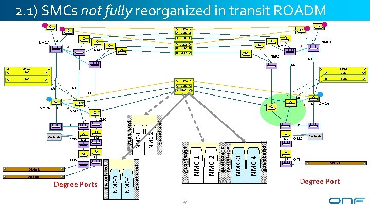
2. 1) SMCs not fully reorganized in transit ROADM NMCA NMC 2 NMCA 2 2 NMCA NMC NMC 1 NMCA 1: 1 SMCA SMC SMC SMCA SMC 1: 1 SMCA Degree Ports guardband NMC-4 guardband NMC-2 guardband 17 NMC-3 OTS Link NMC-2 OTS Link 1. . 2 NMC-1 1 p guardband 1 1. . 2 NMC-3 OTS 1. . 2 guardband OMS 1 NMC-1 SMC 2 p C/L bands 1 SMC guardband 2 guardband 1 NMC-4 SMCA 1 OMS OTS C/L bands OTS Link Degree Port
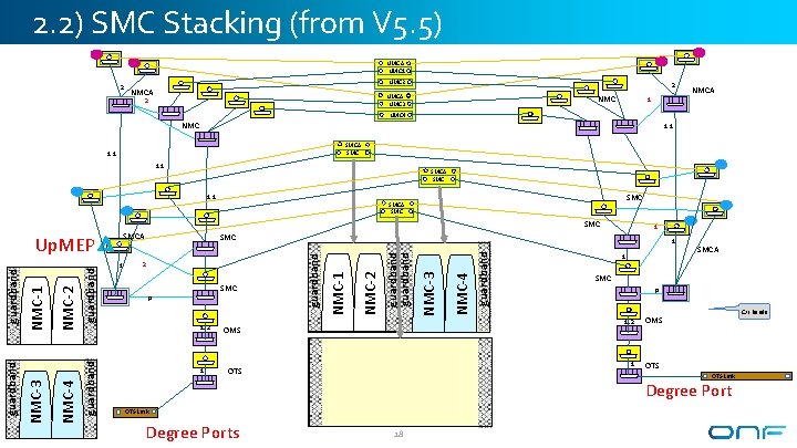
2. 2) SMC Stacking (from V 5. 5) NMCA NMC 1 2 NMCA NMC 3 2 NMC 1 NMCA NMC 4 NMC 1: 1 SMCA SMC guardband NMC-4 NMC-3 guardband OMS OTS Link Degree Ports 1 18 SMCA SMC p 1. . 2 guardband 1 NMC-2 p NMC-1 SMC guardband 2 1 guardband 1 1 SMC 1. . 2 guardband NMC-2 NMC-4 NMC-1 NMC-3 guardband Up. MEP SMCA 1 C/L bands OMS OTS Link Degree Port
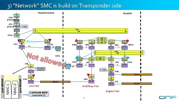
3) “Network” SMC is build on Transponder side TRANSPONDER ODU (ODUCn) OTU (OTUCn) ROADM 1 1. . c c ~Flex. O OTSi. A OTSi 1: 1 OTSi. A NMC 2 OTSi 1: 1 NMC OTSi. A NMC 1 NMC 2 PHTN Not a NMCA llowe SMCA SMC PHTN 1: 1 d Not explicitly modeled represented 1 1: 1 SMC 2 SMCA 1 SMCA 1 1 PHTN 1: 1 SMCA SMC 1: 1 C/L bands 1. . 2 OMS guardband NMC-2 NMC-1 guardband OMS Link OMS 1 1 OMS Link Line Port Guardbands added on ROADM (? ) 1 OTS Add/Drop Port Degree Port 19 OTS Link
ODTN Scenarios 20
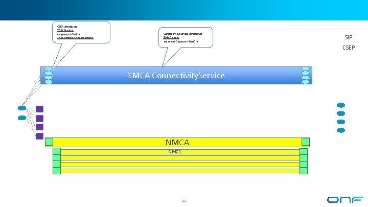
CSEP Attributes TAPI Generic capacity =100 GHz TAPI Photonic Augmentation Connectivity. Service Attributes TAPI Generic requested. Capacity =400 GHz SIP CSEP SMCA Connectivity. Service NMCA NMC 1 21
Alternate Modeling Options 22
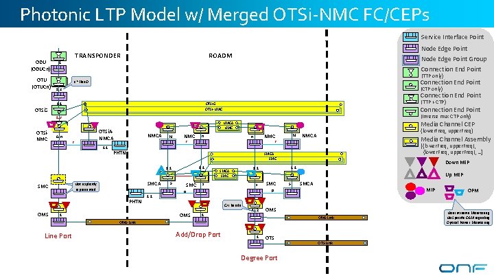
Photonic LTP Model w/ Merged OTSi-NMC FC/CEPs Service Interface Point ODU (ODUCn) OTU (OTUCn) TRANSPONDER Node Edge Point ROADM Node Edge Point Group Connection End Point 1 (TTP only) Connection End Point c ~Flex. O (CTP only) 1. . c Connection End Point 1: 1 (TTP + CTP) OTSi. G OTSi-NMC OTSi. G Connection End Point (Inverse mux CTP only) 1. . r OTSi. NMC OTSi. ANMCA 0. . n r 1: 1 NMCA N NMC n` {lower. Freq, upper. Freq} NMCA Media Channel Assembly [{lower. Freq, upper. Freq}, . . ] SMCA Not explicitly modeled represented 1: 1 S SMCA SMC s Down MEP 1: 1 Up MEP s` SMC S` SMCA MIP p p C/L bands OMS 1 1 1. . 2 OMS Link Line Port N` r PHTN OMS n r 1: 1 SMC Media Channel CEP NMCA NMC Add/Drop Port 1 OTS Degree Port OTS Link OPM Non Intrusive Monitoring No Specific OAM signaling Optical Power Monitoring
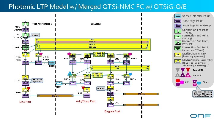
Photonic LTP Model w/ Merged OTSi-NMC FC w/ OTSi. G-O/E Service Interface Point ODU (ODUCn) OTU (OTUCn) TRANSPONDER Node Edge Point ROADM Node Edge Point Group Connection End Point 1 (TTP only) Connection End Point c ~Flex. O 1. . c (CTP only) OTSi. A OTSi. G-O 1: 1 Connection End Point (TTP + CTP) OTSi. G-E OTSi-NMC OTSi. G-E Connection End Point (Inverse mux CTP only) 1. . r OTSi. NMC OTSi. ANMCA 0. . n r 1: 1 NMCA N NMC n` {lower. Freq, upper. Freq} NMCA Media Channel Assembly [{lower. Freq, upper. Freq}, . . ] SMCA Not explicitly modeled represented 1: 1 S SMCA SMC s Down MEP 1: 1 Up MEP s` SMC S` SMCA MIP p p C/L bands OMS 1 1 1. . 2 OMS Link Line Port N` r PHTN OMS n r 1: 1 SMC Media Channel CEP NMCA NMC Add/Drop Port 1 OTS Degree Port OTS Link OPM Non Intrusive Monitoring No Specific OAM signaling Optical Power Monitoring
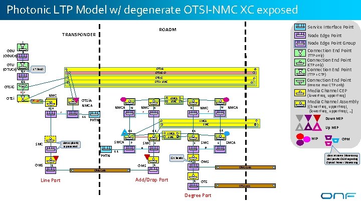
Photonic LTP Model w/ degenerate OTSI-NMC XC exposed ODU (ODUCn) OTU (OTUCn) Service Interface Point ROADM TRANSPONDER Node Edge Point Group Connection End Point 1 (TTP only) Connection End Point 1. . c (CTP only) Connection End Point OTSi. A OTSi. G-O c ~Flex. O (TTP + CTP) OTSi. G OTSi-NMC 1: 1 Connection End Point (Inverse mux CTP only) OTSi. G 1. . r OTSi Media Channel CEP NMC OTSi. ANMCA Fixed 0. . n NMCA N NMC Media Channel Assembly NMC n` [{lower. Freq, upper. Freq}, . . ] NMCA Down MEP SMCA Not explicitly modeled represented PHTN 1: 1 S SMCA SMC s s` Up MEP 1: 1 SMC S` MIP SMCA OPM p p C/L bands OMS 1 1 1. . 2 Add/Drop Port Non Intrusive Monitoring No Specific OAM signaling Optical Power Monitoring OMS Link Line Port N` r PHTN 1: 1 OMS n r r 1: 1 SMC {lower. Freq, upper. Freq} NMCA NMC 1 OTS Degree Port OTS Link
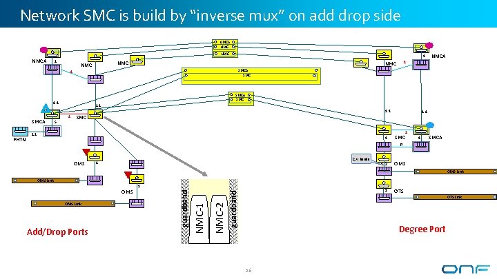
Network SMC is build by “inverse mux” on add drop side NMCA NMC NMCA 1 NMC SMCA SMC 1: 1 SMC 1: 1 1 SMCA p OMS C/L bands 1 1. . 2 OMS Link 1 guardband Add/Drop Ports NMC-2 OMS Link 1 NMC-1 OMS guardband PHTN NMCA SMC 1: 1 S 1 NMC 1 SMCA 1 NMC OTS Degree Port 26 OTS Link
Backup 27
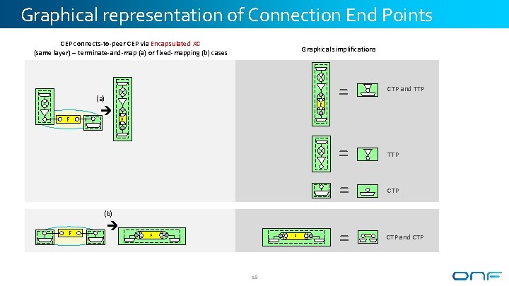
Graphical representation of Connection End Points CEP connects-to-peer CEP via Encapsulated XC (same layer) – terminate-and-map (a) or fixed-mapping (b) cases Graphical simplifications (a) F F = CTP and TTP = CTP and CTP F (b) F F F 28
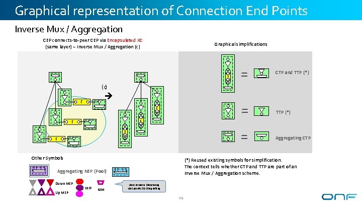
Graphical representation of Connection End Points Inverse Mux / Aggregation CEP connects-to-peer CEP via Encapsulated XC (same layer) – Inverse Mux / Aggregation (c) Graphical simplifications F = CTP and TTP (*) = Aggregating CTP (c) F F F Other Symbols (*) Reused existing symbols for simplification. The context tells whether CTP and TTP are part of an Inverse Mux / Aggregation scheme. Aggregating NEP (Pool) Down MEP Up MEP MIP NIM Non Intrusive Monitoring No Specific OAM signalling 29