NCSX Manufacturing Development of the NCSX Modular Coil


- Slides: 24

NCSX Manufacturing Development of the NCSX Modular Coil Winding Forms and Vacuum Vessel Philip Heitzenroeder, Thomas Brown, George H. Neilson, Wayne Reiersen, Michael Viola, Frank Malinowski, Larry Sutton Princeton Plasma Physics Laboratory Michael Cole; David Williamson; Brad Nelson Oak Ridge National Laboratory Robert Keilbach Washington Group International 20 th IEEE / NPSS Symposium on Fusion Engineering October 14 -17, 2003 1

Abstract NCSX The National Compact Stellarator Experiment (NCSX) is the first of a new class of stellarators known as “compact stellarators”. Stellarators are characterized by three dimensional magnetic fields and plasma shapes and are the best-developed class of magnetic fusion devices after the tokamak. The differentiating feature of the compact stellarator is the use of a small plasma current in conjunction with external magnetic fields to provide the required plasma shaping and confinement. This combination permits a more compact stellarator design. Two of the most critical components are the vacuum vessel and the modular coil winding forms. This paper describes the three-phase program that is being used to develop these components. 2

Motivation for NCSX is the first of a new class of stellarators known as “compact stellarators”. • Stellarators are attractive because they solve critical problems of magnetic fusion energy (MFE): – – Steady state operation without current drive. Stable operation without feedback control or rotation drive. • A significant disadvantage of traditional stellarators is their rather large size. • Compact stellarators improve on the concept by operating at a lower aspect ratio. • They hold the promise of providing the advantages of a traditional stellarator in a smaller size device. • To permit an evaluation of the cost vs. benefit of the compact stellarator. – Cost: 3 D geometry makes core components more expensive. – Benefit: Eliminate disruptions, delete feedback and current drive experiment. 3

The National Compact Stellarator Experiment NCSX will be located at the Princeton Plasma Physics Laboratory in the combined former Test Cells of PLT and PBX. • First Plasma Scheduled for September, 2007. • Major radius, R = 1. 4 m • Magnetic Field Strength (B) =2. 0 T (0. 2 s pulse) • All coils, including the Toroidal Field (TF), Poloidal Field (PF), Modular Coils, and Trim Coils are cryoresistive 4

Much NCSX is Conventional In Design and Construction, But There Are Two Key Components Which Are Not NCSX The Conventional Components The Unconventional Components NCSX Vacuum Vessel TF, PF, and Trim Coils • Are conventional, cryo cooled copper coils. • Low stress; conservative designs. • Structural supports consist of relatively straightforward stainless steel castings. NCSX Modular Coils These were recognized as unusual and challenging from the manufacturing point of view from their conception. The questions which often come to mind : How can these parts be made? Can these tolerances be achieved? What will the costs and schedules be? 5

Why We are Focusing On The Vacuum Vessel and Modular Coil Winding Forms NCSX • They are key components. – The vacuum vessel provides the environment necessary for the plasma and supports the divertors and plasma facing components – The winding forms define the precise shape and must react electromagnetic loads that are as high as 7000 lbs. /in. of winding. • Magnetic islands caused by field errors must contain <10% of the total flux. • Current centers of the windings be located within +/-0. 060” to achieve this. – This is allocated equally between the winding form, the windings, and assembly (+/0. 020” each…not a lot!). • • • They are highly shaped. – Need to rely on state-of-the art computer aided design (CAD) and computer aided manufacture (CAM). – Laser scanners and multi-link component measuring systems are needed to verify shape and dimensions. They have tight tolerances for parts of their size and complexity: – Vacuum vessel profile: +/- 0. 188”; Winding forms: machined surfaces +/- 0. 010”. The winding form is on the critical path and the vacuum vessel is very near it. The Project needs both to be completed on specification, on schedule and on budget. 6

NCSX Vacuum Vessel Overview NCSX • Provide a low impurity vacuum environment for the plasma. • Vacuum level 10 -8 torr; • 150 0 C bakeout. • Made of Inconel 625, 3/8” thick. • Fabricated in three field periods, welded together at assembly • Has a total of (72) ports 7

Vessel Shape and Dimensions Must Be Tightly Controlled for Assembly NCSX View Showing Clearances between Major Components – Vessel shape & size has to be compatible not only with plasma, but with divertors and other in-vessel components. – Tolerances have to be tightly controlled to provide the clearances necessary to slide the modular coils over the vessel. 8

Overview of NCSX’s Modular Coil Winding Forms NCSX • They define the precise shapes of the modular coil windings that are required. • They must withstand electromagnetic loads: up to 7000 lbs. / in. with deflections <0. 020”. • Made of a machined stainless steel casting. • Machined surface tolerance: +/- 0. 010” • Six of each of three winding form types are required. • The modular coil winding forms bolt together to form a complete torus. • This torus also supports the vacuum vessel and interfaces with the TF and PF coils. Type C Type B Type A 9

The Modular Coil Assembly NCSX Field Period Boundary C B A Field Period Boundary • Shell thickness: 1. 5” (some higher stress areas are thicker) • Total weight of completed assembly: 125, 000 lbs. 10

A Three-Phase Program Is Underway to Develop These Two key Components NCSX • Phase I. Limited manufacturing Studies – Completed • In progress – Goals: to obtain industrial inputs on the designs of the modular coil winding forms, windings, and the vacuum vessel. To obtain industrial inputs on the specifications, costs, and schedules. Phase II. Detailed Manufacturing Studies & Fabrication of a Type C Winding Form Prototype and a Prototype 200 Vacuum Vessel Sector – – Four teams are participating (2 for the winding forms; two for the VV) Goals: • (complete June ’ 04) • • • Beginning • in July, ’ 04. To develop detailed manufacturing and quality assurance plans for the “production” parts. To develop cost and schedule information for use in developing project plans. To produce prototypes. To qualify suppliers for the production phase through this effort. Phase III. Production – We intend to award a fixed price and schedule contract to one of the Phase II study teams for the winding forms and one for the vacuum vessel based on an evaluation of their Phase II performance. 11

The Phase I Vacuum Vessel Studies Indicated That It Could Be Fabricated By A Variety of Techniques NCSX • We found that not only could the vessel be built, but it could be built with a variety of techniques including Hot Forming, Cold Forming, Explosive Forming, and possibly casting. • The studies provided technical , cost, and schedule feedback that were used in project planning. 12

The Phase I Modular Coil Studies Changed our Perception of How They Should be Fabricated NCSX • Through these studies, we found that the winding forms are: – – Within the current state of the art. Can be produced by a number of companies. • Concerning the windings, we found that: – Procuring the winding forms and windings as a single subcontract would not be advantageous. • • There would be less competition. The field of companies that would handle both the “heavy manufacturing” required of the form and the “electromechanical manufactuing” required of the windings would be greatly reduced. Risks associated with the windings would be better mitigated by doing the winding portion at PPPL. – – Close coupling between the design and the R&D and production activities enhances the design optimization process. It is a good fit to PPPL’s extensive coil design and fabrication expertise. We also found that we could substantially improve the schedule in this manner. There is greater flexibility to react to unanticipated production or assembly situations. • These findings led to our current plan of procuring the winding forms from industry and fabricating the windings at PPPL. 13

The Phase II “Prototyping Phase” Is Currently Underway NCSX ü ü Develop ü Manufacturingü Methods ü • Demonstrate • Manufacture • • Describe manufacturing methods. Describe the non-destructive testing and measuring techniques. Recommend changes to design or specification. Develop Preliminary Manufacturing / Inspection / Test (MIT) and Quality Assurance (QA) Plans for production parts. Prepare budgetary cost and schedule estimates. Develop MIT / QA plans for the prototype. Manufacture the Prototypes Develop Final MIT / QA Plans for the Production Parts Develop a firm fixed price and schedule proposal for the production parts. Ready for Production 14

The Vacuum Vessel Prototypes Consist of 200 Sectors with A Port NCSX Goals: • To produce a prototype VV sector. • To provide experience in manufacturing prototypical parts so firm fixed price proposals can be developed which do not have excessive contingency built in. • The prototype consists of a 20° sector (chosen for good demonstration of shape forming) and a vacuum port assembly to demonstrate the ability to produce vacuum-quality welds with minimal distortion. 15

Full-Scale Type C Winding Forms Will Be Produced As Prototypes NCSX • Profile within 0. 020” – bilateral tolerance +/-0. 010” from reference surface. • As cast thickness tolerance +/- 0. 25”. Surface profile must be within 0. 5” of CAD data. Coil M 3 Weight(lb): Winding Form 5964 Windings/Asm 1092 Total 7056 46 -in 77 in 106 -in 16

Current Phase II Status NCSX • Manufacturing methods study phases completed. • Manufacturing / Inspection / Test / Quality Assurance Plans have been developed and are being finalized. – Supporting procedures are currently being developed. • The Vacuum Vessel subcontractors were authorized to proceed with the vacuum vessel prototype fabrication in August. – First prototype may be completed before the end of the year. • Authorization to proceed with the modular coil winding form prototypes is imminent. – Prototypes will be completed by June ’ 04. 17

Highlights of the Vacuum Vessel Phase II Study NCSX The First Set of Punches and Dies for the Vacuum Vessel During Fabrication At Major Tool and Machine, Inc. , Indianapolis, In. 18

Vessel Manufacture NCSX • • Dies are machined. Panels are cold pressed. (Segmentation determined by Vendor. ) – • • Measurements taken using CMM or gages Panels welded together on fixture Mirror every half period (60°) More measurements taken – • • • (Heat treatment requirements evaluated during R&D) permits leak check minimizes distortion Main flanges attached Leak check entire vessel and port welds between thermal cycling Ports cut off to leave stubs – – • • 60 Degree Half-Period 6 Piece Segmentation Scheme 60° segments married Ports welded on before cutting holes. – – • • (Prototype consists of a 20° sector which involves about 5 segments) reinforces vessel permits port alignment Holes bored Vessel shipped 19

Highlights of the Winding Form Phase II Study: Both Teams Have Developed Casting Alloys which Meet NCSX’s Requirements NCSX Property at 293 K At 77 K Yield strength >180 MPa (26 ksi) >360 MPa (52 ksi) Ultimate tensile strength >360 MPa (52 ksi) >690 MPa (99. 7 ksi) Min. elongation 30% >9. 7 W/m-K >83 x 10 -8 ohm-m >64 x 10 -8 ohm-m Thermal conductivity Electrical resistivity Relative magnetic permeability <1. 02 20

Outline of the Modular Coil Fabrication Method NCSX Mold Prep. Casting. Machining 21

We Are Preparing to Begin the Production Phase III NCSX Complete Prototypes – Final Design Review for the vacuum vessel will be held in April after the prototypes have been completed and evaluated. – Final Design Review for the winding forms will be held in April. The winding forms are expected to be in their final machining phase at that point. Produce a Final Manufacturing / Inspection / Test / Quality Assurance Plan for the “Production” Winding Forms – Subcontractors will prepare these after the prototypes have been completed. – This plan will reflect their experience in manufacturing the prototype. – Subcontractor proposals will be developed based on these. Produce a Firm Fixed Price and Schedule Proposal – Subcontract Proposal Evaluation Boards (SPEB) will evaluate the proposals submitted. – The Production Subcontract will be awarded by the end of July. The final selection will be based on: • • • Evaluation of the prototypes, “Best value” evaluation of the proposals. Business factors, including experience in working with them during the Phase II efforts. Begin The Production Phase – Vacuum vessel July ’ 04 -September ’ 06 – Winding forms: July ’ 04 -January, ’ 06. 22

Summary NCSX • • • A three-phase program is being used to lead the Vacuum Vessel and Modular Coil Winding Forms through their design phases, into the prototype phase, and finally into the production phase. – Elements are structured to reduce technical, schedular, and financial risks. We have completed the Phase I (Limited Manufacturing Studies) last year during the CDR, and this has provided a great deal of input into the design, engineering specifications, and project planning. Most importantly, WE LEARNED THAT THE VACUUM VESSEL AND WINDING FORMS CAN BE BUILT! We are now well into the Phase II (Detailed Manufacturing Studies / Prototypes) and will conclude this phase with the production of prototypes and Firm Fixed Price and Schedule Proposals from the Phase II participants. We look forward to beginning the Phase III Production Phase in July ’ 04 This process is advancing well towards the objectives of reducing the technical, schedule, and financial risks associated with these unusual, but 23 key components of NCSX.

Acknowledgements NCSX Our sincere thanks to the industrial participants for their many contributions to these studies: Phase I: • Osterby Gjuteri, AB; Osterbybruk, Sweden; • Mitsubishi Electric Power Products, Inc. Warrendale, Pa. ; • Hitachi, Ltd. , Tokyo, Japan; • Ansaldo Superconduttori s. p. a. , Genova, Italy; • Atlas Foundry and Machine, Tacoma, Wa. ; • PCC Structurals, Portland, Or. • International Association “INTERM”, Kyiv, Ukraine. Phase II: • Major Tool and Machine, Inc. ; Indianapolis, In. • Rohwedder, Inc. , Orlando, Fla. ; • Energy Industries of Ohio (EIO); Independence, Oh. – • And team members Atlantic Technical Components; buy. Castings, Inc. ; Metal. Tek International; Magna Machine Co. ; CA Lawton Co. ; Deformation Control Technology Inc. ; Finite Solutions Inc. ; Altair Engineering Inc. ; ARACOR J. P. Pattern, Inc. , Butler, Wis. – And team members TKS Innovation, LLC; Waukesha Foundry, Inc. ; Remmelle Engineering, Inc. This work is supported by USDOE Contract No. DE-AC 02 -76 -CHO 3073. 24
 Series coil and multi-turn coil
 Manufacturing cost vs non manufacturing cost
 Process costing vs job costing
 Uncontrollable cost example
 Manufacturing cost vs non manufacturing cost
 Additively
 Hình ảnh bộ gõ cơ thể búng tay
 Lp html
 Bổ thể
 Tỉ lệ cơ thể trẻ em
 Chó sói
 Chụp phim tư thế worms-breton
 Chúa yêu trần thế alleluia
 Các môn thể thao bắt đầu bằng tiếng chạy
 Thế nào là hệ số cao nhất
 Các châu lục và đại dương trên thế giới
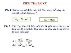
 Cong thức tính động năng
 Trời xanh đây là của chúng ta thể thơ
 Mật thư anh em như thể tay chân
 Phép trừ bù
 Phản ứng thế ankan
 Các châu lục và đại dương trên thế giới
 Thơ thất ngôn tứ tuyệt đường luật
 Quá trình desamine hóa có thể tạo ra
 Một số thể thơ truyền thống
