Machine Tools Introduction Machine Tool It is defined


 a horizontal-spindle column-and-knee")


 Slab milling b) Face milling c) End milling Arbor Cutter Spindle")


- Slides: 66
Machine Tools
Introduction • Machine Tool - It is defined as the machines used for carrying out metal cutting processes & surface finishing processes. • Machine tool is a power driven machine used for producing the components of required shape & size with desired accuracy & surface finish by removing the excess material from the work pieces.
Machine Tools According to size of chip removed Larger sized chips like lathe machine, drilling machine etc. Smaller sized chips like grinding machine , lapping machine etc According to desired purpose Single-purpose , Multi –purpose & Special purpose machine tool
Lathe Machine • It is known as the mother of all the machine tools. It is the oldest, simplest, versatile and the most widely used machine tools. • A lathe removes the material by rotating a work piece against a single point cutting tool. • It is used for producing cylindrical surface. Also it can produce flat surface with facing operation, internal holes, thread cutting, tapering etc.
BLOCK DIAGRAM OF LATHE MACHINE
Swing: It is the maximum diameter of work piece that can be revolved over the bed. Over all length of bed: It is the total length of the lathe itself. Distance between centers: It is the distance between live center & dead center. Maximum and Minimum spindle speed
Working Principle • Lathe is a machine tool which holds workpiece securely between two rigid & strong supports, called as centres or in a chuck or face plate, while workpiece revolves. • The cutting tool is rigidly held & supported in a tool post & fed against revolving workpiece. While workpiece revolves about its own axis, tool is made to move in parallel, perpendicular or at an inclination with axis of material to be cut. • So the metal is removed to give desired shape & size.
Lathe Machine Operations 1. Straight & Taper turning : Operation is performed for producing a cylindrical surface by removing excess material from workpiece to reduce diameter. The cutting tool is held in tool post & fed into rotating work parallel to lathe axis. Tool used in this operation is called as turning tool.
• Removing the material from the end surface or face of work piece. FACING • Produces a flat surface. • Used for reducing the length of the work piece. • The tool motion is perpendicular to the axis of the lathe spindle.
DRILLING It is the process of producing cylindrical hole by means of cutting tool known as drill. During operation drill is fed by rotating hand wheel of the tailstock in clockwise direction.
BORING It is the process of enlarging the already existing hole in the work piece. also called as Internal Turning.
KNURLING It is the Process of embossing a diamond shaped pattern on the surface of work piece using a tool called knurling tool. • Provides a non-slip grip on the surface • It gives decorative look
THREAD CUTTING Process of producing the helical ‘ V ‘ grooves on the surface with the help of lead screw
CHAMFERING • Process of beveling the sharp ends of the work piece. • Chamfering is provided: for avoiding the injuries to the persons handling the finished products and for aesthetic look to the finished product.
GROOVING PARTING Process of cutting a work piece into two parts. Process of providing a narrow groove on the cylindrical surface of the work piece.
Drilling Machine
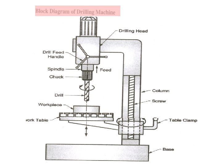
DRILLING MACHINES • Drilling is an operation through which holes are produced in a fixed solid material by using a revolving tool which is called as drill. • The machine tool used for producing the holes in a solid material is called as drilling machine.
WORKING PRINCIPLE • The work piece is clamped firmly on the work table by using nut, bolts or jaws & the tool is used to produce holes in solid material called as drill tool, which is fitted in drill chuck. • The rotating drill is made of harder material than that of the work piece and it is fed against the stationary work piece. • During the operation, the material is removed in the form of medium sized chips. • It is important to note that during the process high amount of heat is generated due to friction, hence continuous supply of coolant is required.
TYPES OF DRILLING MACHINES: Drilling machine are manufactured in different sizes and varieties to suit different types of workpieces. They are classified as follows: 1) Portable drilling machine 2) Sensitive or Bench drilling machine 3) Upright drilling machine 4) Radial drilling machine 5) Gang drilling machine 6) Multi-spindle drilling machine 7) Deep hole drilling machine 8) Automatic drilling machine
DRILLING MACHINE OPERATIONS 1. DRILLING Drilling is the operation of producing a circular hole in a solid metal by using revolving tool which is called drill. 2. REAMING Reaming is the operation of finishing a hole which has been previously drilled and has a coarse surface finish. The operation is performed by using a multi tooth tool called as reamer. 3. BORING The boring is the process of enlarging a drilled hole by using an adjustable cutting tool which is called as boring tool. It is important to note that the boring tool is having only one cutting edge.
4. COUNTER SINKING Counter sinking operation is used for enlarging the end of a hole and to give it a conical shape for a short distance. The standard countersinks have the included angles of 60, 82 or 90 degrees and cutting edges of tool are at the conical surface. 5. SPOT FACING It is the operation of smoothing the surface around a hole for the seat of a nut or the head of a screw. For spot facing counter bore or special spot facing tool is used. 6. TAPPING Tapping is an operation of cutting internal threads by using a cutting tool called as tap. For tapping purpose, the machine should be equipped with a reversible motor or some other reversing mechanism.
Deep Hole Drilling • Deep hole drilling is when you drill a deep hole in your workpiece. Usually, the depth is ten times the size of the diameter of the hole. You will be needing special equipment to drill such hole. • There are other types of drilling as well. Such as Micro drilling, Vibration drilling etc.
Reaming : It is a finishing operation because a very small amount of material is removed during this operation. For performing reaming a multi teeth tool is used, which is called as reamer.
Milling Machines Milling: A process in which a rotating multi-tooth cutter removes material while traveling along various axes with respect to the work piece. Types of Milling Machines: • Horizontal and vertical Type Milling Machines • Column-and-Knee Type Milling Machines • Bed-type Milling Machine • CNC Vertical-Spindle Milling Machine
Milling machine is one of the most versatile conventional machine tools with a wide range of metal cutting capability. Many complicated operations such as indexing, gang milling, and straddle milling etc. can be carried out on a milling machine.
Components of Milling Machine Most milling machines have self-contained electric drive motors, coolant systems, variable spindle speeds, and power -operated adjustable worktable, which mounts and feeds the workpiece.
• The basic components of these machines are as follows: • Worktable: on which the workpiece is clamped using T-slots. The table moves longitudinally relative to the saddle. • Saddle: supports the table and can move in the transverse direction. • Knee: supports the saddle and gives the table vertical movement so that thedepth of cut can be adjusted and workpieces with various heights can be accommodated. • Overerarm: used on horizontal machines; it is adjustable to accommodate different arbor lengths. • Head: contains the spindle and cutter holders. In vertical machines, the head may be fixed or can be adjusted vertically, and it can be swiveled in a vertical plane on the column for cutting tapered surfaces.
Types of Milling machines Horizontal milling machines vertical milling
Universal Milling Cutting action is carried out Machine by feeding the workpiece against the rotating cutter. Thus, the spindle speed, the table feed, the depth of cut, and the rotating direction of the cutter become the main parameters of the process. Good results can only be achieved with a well balanced settings of these parameters.
Column-and-Knee Type Milling Machines Figure : - Schematic illustration of (a) a horizontal-spindle column-and-knee type milling machine and (b) vertical-spindle column-and-knee type milling machine.
Bed-type Milling Machine FIGURE : - Schematic illustration of a bed-type milling machine.
Five-Axis Profile Milling Machine Figure: - Schematic illustration of a five-axis profile milling machine. Note that there are three principal linear and two angular movements of machine components.
Milling Cutters The milling cutter is a rotary cutting tool, often with multiple cutting points. The cutting surfaces of a milling cutter are generally made of a hard and temperature-resistant material, so that they wear slowly. A low cost cutter may have surfaces made of high speed steel. More expensive but slowerwearing materials include cemented carbide.
Milling Cutters a. Straddle: more cutters are used to machine two parallel surfaces on the workpiece b. Form milling produces curved profiles using cutters that have specially shaped teeth C & d. Slotting and slitting operations are performed with circular cutters. Figure 24. 11 Cutters for (a) straddle milling, (b) form milling, (c) slotting, and (d) slitting with a milling cutter.
T-slot Cutter Profile cutter milling saw angular cutter Insert Tip cutter shell end
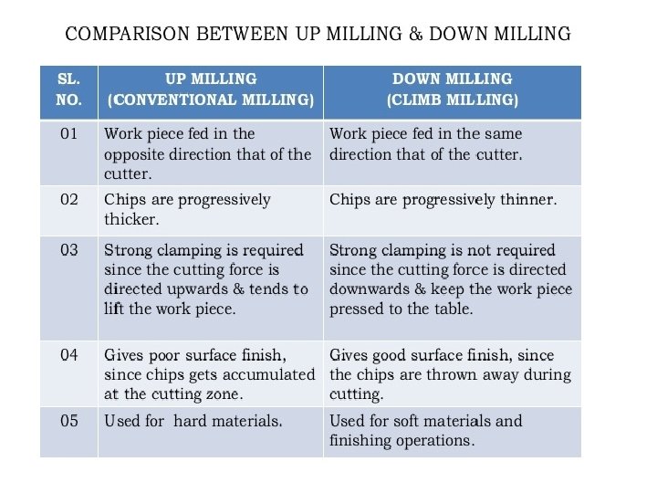
Milling Operations Figure : - Schematic illustration of conventional/Up milling and climb/down milling.
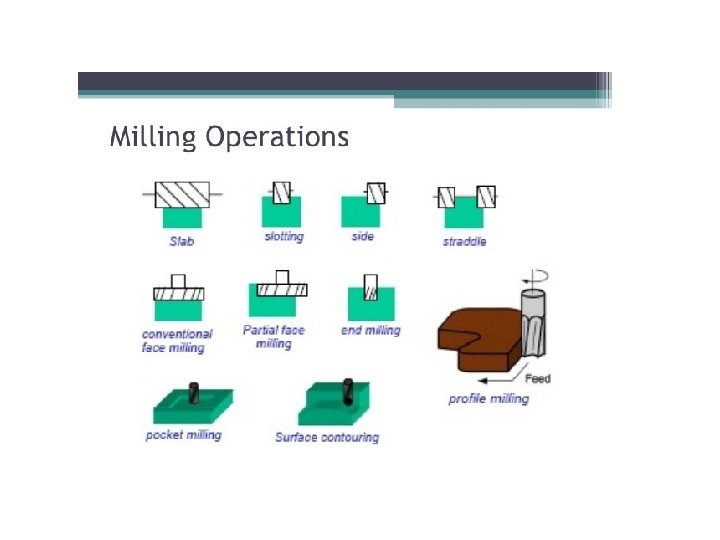
Milling Processes a) Slab milling b) Face milling c) End milling Arbor Cutter Spindle Arbor d) e) Shank End mill
Parts Made with Machining Processes Figure : Typical parts and shapes that can be produced with the machining processes described in this chapter.
Grinding Machine
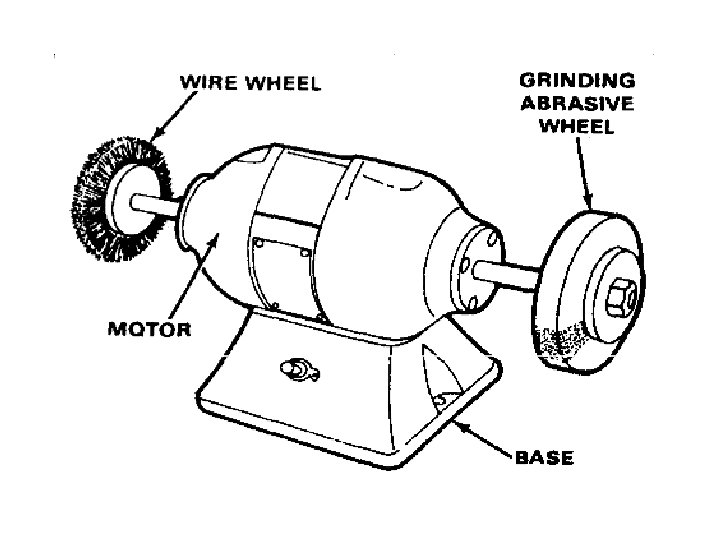
Grinding Machine • Grinding is process of imparting the good surface finish and high dimensional accuracy to the components with the negligible removal of material by the use of rotary abrasive tool called grinding wheel. • Such grinding wheels made up of fine grains of abrasive materials held together by bonding material & each grains of abrasive material acts like a single point cutting tool.
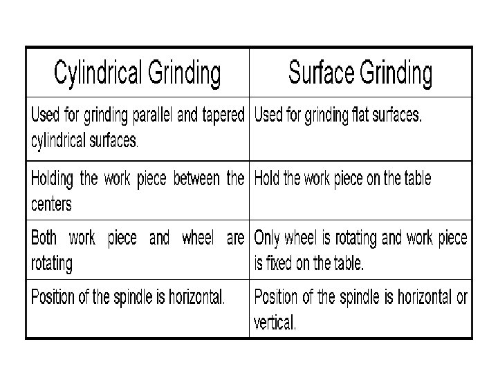
• Grinding machine is a machine tool in which the material is removed in the form of fine small size chips, almost as dust particles by using rotating abrasive wheel called grinding wheel. • Cylindrical Grinding and Surface Grinding
Grinding wheel and Surface interaction
§ The grinding operations are classified on the basis of surface finish: • Rough (Non-Precision) Grinding • Fine (Precision) Grinding § Rough (Non-Precision) Grinding: • In this process, the excess material is removed from castings, forgings or weld material • It also removes the sharp corners or unwanted projection from the work piece. § Fine (Precision) Grinding: • It is used for providing good surface finish and high dimensional accuracy to the work piece.
Types of Grinding Machine 1. Cylindrical Grinding Machine. 2. Internal Grinding Machine. 3. Center less Grinding Machine. 4. Surface Grinding Machine. 5. Special Purpose Grinding Machines.
Cylindrical Grinding Machine Applications- use for grinding of rotary elements like axles, shaft , splines etc. .
Internal Grinding Machine • Internal grinding is the process of grinding the hole of cylindrical work piece. Applications- Use for grinding of bore of cylinder , inner surface of ball bearing etc.
Centreless Grinding Machine • Centre less grinding is the process of grinding the cylindrical surface of the workpiece which cannot be held between the centers Applications- Centreless is used for the grinding of crankpins , Piston pins drills, busings , small diameter shafts , piston tubes ball and roller bearings bearings.
Surface Grinding Machine • Surface Grinding is the process of grinding the flat surface of the workpiece.
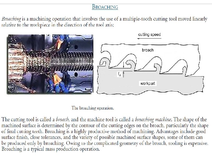
• It is a multiple tooth cutting operation with the tool reciprocating as in sawing machine. • Machining operation completed in a single stroke. • Teeth are at a gradually increasing height. • Broach are originally developed for machining internal keyways. • It is extensively used in mass automobile component manufacture for various other surfaces.
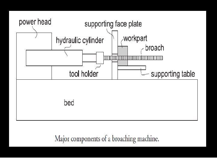
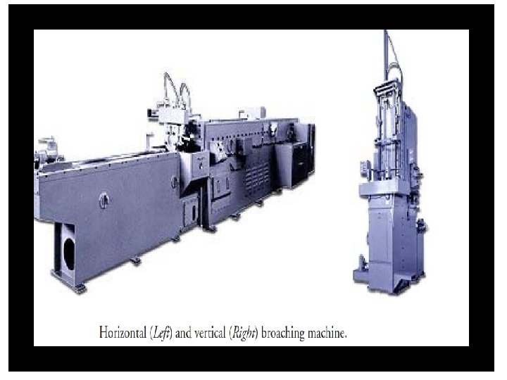
BROACHING • A multiple tooth cutting tool • The forming tool moves linearly relative to the workpiece in the direction of the tool axis. 58
Applications of broaching • Examples of internal shapes that can be done on broaching machine.
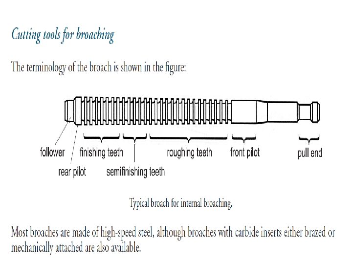
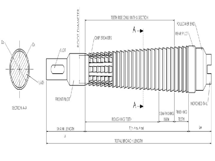
Broach tool nomencluture
Broaching tool 62
broaching
THANK YOU !!!