CHAPTER 3 MILLING MACHINE 1 1 Introduction 1


 through the material,")
 part of the tool which is")
 -used for")


, tungsten")
 Types of Horizontal Milling Cutter: ~ Plain Milling Cutters – most")

 in diameter and")


- Slides: 50
CHAPTER 3 MILLING MACHINE 1. 1 Introduction 1. 2 Vertical Milling Machines 1. 2. 1 Introduction 1. 2. 2 Cutting Speed, Feed, and Depth of Cut 1. 2. 3 Vertical Milling Cutter 1. 2. 4 Vertical Milling Operations 1. 3 Horizontal Milling Machines 1. 3. 1 Introduction 1. 3. 2 Horizontal Milling Cutter
1. 1 Introduction • • Milling machines are machine tools used to produce one or more machined surfaces on the workpiece, this is done by one or more rotary milling cutters having single or multiple cutting edges. Workpiece held on work table or holding device and brought into contact with cutter. A milling machine is a versatile machine tool which can handle a variety of operations normally such as milling for flat and irregular shaped surfaces, but also for gear thread cutting, drilling, boring, reaming and slotting operations. Two types of milling machines: ~ vertical milling machines. ~ horizontal milling machines.
Figure 3. 1: Milling Process and Operations
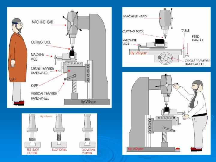
1. 2 Vertical Milling Machines 1. 2. 1 Introduction • Vertical milling machine have two types: ~ ram-type is most commonly found in industry because of its simplicity and ease setup. ~ 2 -axis control a step between the standard milling machine and the CNC machining center, can be operated manually or automatic. • This machine have the vertical spindle with longitudinal and traverse (crossfeed) movements of a milling machine. • The longitudinal and crossfeed movements of the table may be operated by hand or by automatic feeds. • It is used to machined flat, angular and multi-shaped surfaces which can be in one, two, or three planes (X, Y, Z axes). • This machine can be used for milling, drilling, boring, and reaming operations.
• Parts of the Ram-Type Vertical Milling ~ Base is made of ribbed cast iron and maybe contain a coolant reservoir. ~ Column is often cast with the base. Machined face provides ways for vertical movement of knee and Upper part machines to receive turret where overarm mounted. ~ Head is attached to end of ram. Provision is made to swivel the head in one plane. Motor mounted on top of head, provides drive to spindle through V-belts. ~ Knee is moves up and down on face of column and support the saddle and table.
Figure 3. 2: Ram-type Vertical Milling Machine
• Types of Movement in Vertical Milling Machines: ~ Principal Movement (Spindle Or Cutting). The milling cutter has a rotary movement by means of a spindle drive system. The rotation speed of the milling cutter depends upon the cutting speed required. ~ Feed Movement (Longitudinal And Transverse). The feed movements of the longitudinal and transverse can be manually operated or by automatic feed by means of the feed drive system. The longitudinal movement is carried out on a knee by means of the table slide. ~ Vertical Feed Movements. Vertical feed is normally carried out by raising the milling table to get the cutting depth correct. It can be manually operated or by automatic feed.
1. 2. 2 Cutting Speed, Feed, and Depth of Cut • The most important factors affecting the efficiency of a milling operation are cutting speed, feed, and depth of cut. • Cutting Speed ~ too slowly, time wasted. ~ too fast, time lost in replacing/regrinding cutters. • Feed Rate ~ too slowly, time wasted and cutter chatter. ~ too fast, cutter teeth can be broken. • Depth of Cut ~ several shallow cuts wastes time.
• Calculation Cutting Speed ~ In milling machine, cutter revolves r/min depending on diameter for cutting speed. ~ Important factors in determine cutting speed its type of work material, cutter material, diameter cutter, surface finish required, depth of cut, and rigidity of machine and work setup. Table 3. 1: Table Milling Machine Cutting Speeds MILLING MACHINE CUTTING SPEEDS MATERIAL Machine Steel Tool Steel Cast Iron Bronze Aluminum HIGH SPEED STEEL CUTTER CARBIDE CUTTER m/min 21 - 30 18 - 20 15 - 25 20 - 35 150 - 300 45 - 75 40 - 60 60 - 120 150 - 300
~ Formula for r/min of the milling machine: simplify formula ~ Example, calculate the r/min required for a 75 mm diameter highspeed steel milling cutter when cutting machine steel (CS 30 m/min). • Calculation Feed Rate ~ Defined as distance in mm per minute that work moves into cutter. ~ Milling feed is determined by multiplying chip size (chip per tooth) desired, number of teeth in cutter, and r/min of cutter. Chip or feed, per tooth (CPT or (FPT) is amount of material that should be removed by each tooth of the cutter.
~ Factors in feed rate depends on depth and width of cut, design or type of cutter, sharpness of the cutter, workpiece material, surface finish required, and rigidity of machine and work setup. ~ Formula for feed of the milling machine: Feed = no. of cutter teeth x feed/tooth x cutter r/min Feed (mm/min) = N x CPT x r/min ~ Example, Calculate the feed in millimeters per minute for a 75 mm diameter, six-tooth helical carbide milling cutter when machining cast-iron (CS 60). First, calculate proper r/min for cutter: Feed(mm/min) = N x CPT (table page 470) x r/min = 6 x 0. 33 x 256 = 507 mm/min
• Feed is the direction in which the workpiece is fed into the cutter. The method of direction of feed its: ~ Conventional (up milling) is to fed the workpiece against the rotation direction of the cutter. Figure 3. 3: Conventional Milling
~ Climb milling is used when cutter and workpiece going in same direction. Figure 3. 4: Climb Milling
• Depth of Cut ~ Roughing cuts should be deep - Feed heavy as the work and machine will permit - May be taken with helical cutters having fewer teeth ~ Finishing cuts should be light with finer feed - Depth of cut at least 0. 4 mm. - Feed should be reduced rather than cutter speeded up
1. 2. 3 Vertical Milling Cutter • Milling cutters are manufactured in many types and sizes. The types of cutters are distinguished by their form and application. • The workpiece material determines the cutter type and cutter material. • It is distinguished from the drill bit, in its application, geometry, and manufacture. While a drill bit can only cut in the axial direction, a milling bit can generally cut in all directions, though some cannot cut axially. • End mills are used in milling applications such as profile milling, tracer milling, face milling, plunging, etc. • Most milling cutters are made of high speed steel (HSS) or tungsten carbide.
• • HSS end mills: ~ Relatively inexpensive, easy to get and do jobs quite well. ~ Capable of machining with close tolerances. ~ Single most versatile rotary tools used on conventional and CNC machines. ~ If need harder tool, frequent solution is cobalt end mill -Less expensive than carbide, long tool life. Carbide end mills: ~ Carbide properties vs. HSS tool materials -Higher hardness -Greater rigidity -Can withstand higher cutting temperatures Can run at higher speeds and feeds ~ Increasing production rates ~ Providing long tool life High-performance tool material
• Features of a Milling Cutter: ~ Flutes / teeth: The flutes of the milling bit are the deep helical grooves running up the cutter, while the sharp blade along the edge of the flute is known as the tooth. The tooth cuts the material, and chips of this material are pulled up the flute by the rotation of the cutter. There is almost always one tooth per flute, but some cutters have two teeth per flute. ~ Helix angle: The flutes of a milling cutter are almost always helical. If the flutes were straight, the whole tooth would impact the material at once, causing vibration and reducing accuracy and surface quality. Setting the flutes at an angle allows the tooth to enter the material gradually, reducing vibration. Typically, finishing cutters have a higher rake angle (tighter helix) to give a better finish.
~ Center cutting: Some milling cutters can drill straight down (plunge) through the material, while others cannot. This is because the teeth of some cutters do not go all the way to the centre of the end face. However, these cutters can cut downwards at an angle of 45 degrees or so. ~ Roughing or Finishing: A roughing cutter may have serrated teeth for breaking the chips of material into smaller pieces. These teeth leave a rough surface behind. A finishing cutter may have a large number (4 or more) teeth for removing material carefully. ~ Coatings: Tool coatings can have a great influence on the cutting process. The right coating can increase cutting speed and tool life, and improve the surface finish. Polycrystalline Diamond (PCD) is an exceptionally hard coating used on cutters which must withstand high abrasive wear.
~ Shank: The shank is the cylindrical (non-fluted) part of the tool which is used to hold and locate it in the tool holder. A shank may be perfectly round, and held by friction, where a grub screw makes contact for increased torque without the tool slipping. Figure 3. 6: End Mill Cutter with Two Flutes
• End Mill Shapes: ~ Flat bottom end mill (most common) -used for all operations requiring flat bottom and sharp corner between wall and bottom ~ End mill with full radium (ball nose end mill) -used for 3 D machining of various surfaces ~ End mill with corner radium (bull nose end mill) -used for either 3 D work or flat surfaces that require corner radius between wall and bottom Figure 3. 7: Three Common Shapes ground on End Mills
• Fly cutters is composed of a body into which one or two tool bits are inserted. As the entire unit rotates, the tool bits take broad, shallow facing cuts. Fly cutters are analogous to face mills in that their purpose is face milling and their individual cutters are replaceable. Face mills are more ideal in various respects (e. g. , rigidity, indexability of inserts without disturbing effective cutter diameter or tool length offset, depth-of-cut capability), but tend to be expensive, whereas fly cutters are very inexpensive. Figure 3. 8: Fly Cutter
1. 2. 4 Vertical Milling Operations • Defined by the type of cutter used and the path of that cutter to remove material from the workpiece. ~ End milling - An end mill makes either peripheral or slot cuts, determined by the step-over distance, across the workpiece in order to machine a specified feature, such as a profile, slot, pocket, or even a complex surface contour. The depth of the feature may be machined in a single pass or may be reached by machining at a smaller axial depth of cut and making multiple passes. Figure 3. 9: Pocket Milling Operation
~ Chamfer milling - A chamfer end mill makes a peripheral cut along an edge of the workpiece or a feature to create an angled surface, known as a chamfer. This chamfer, typically with a 45 degree angle, can be machined on either the exterior or interior of a part and can follow either a straight or curved path. Figure 3. 10: Chamfer Milling Operation
~ Face milling - A face mill machines a flat surface of the workpiece in order to provide a smooth finish. The depth of the face, typically very small, may be machined in a single pass or may be reached by machining at a smaller axial depth of cut and making multiple passes. Figure 3. 11: Face Milling Operation
~ Drilling - A drill enters the workpiece axially and cuts a hole with a diameter equal to that of the tool. A drilling operation can produce a blind hole, which extends to some depth inside the workpiece, or a through hole, which extends completely through the workpiece. Figure 3. 12: Drilling Mill Operation
~ Boring - A boring tool enters the workpiece axially and cuts along an internal surface to form different features. The boring tool is a single-point cutting tool, which can be set to cut the desired diameter by using an adjustable boring head. Boring is commonly performed after drilling a hole in order to enlarge the diameter or obtain more precise dimensions. Figure 3. 13: Boring Operation
~ Counterboring - An counterbore tool enters the workpiece axially and enlarges the top portion of an existing hole to the diameter of the tool. Counterboring is often performed after drilling to provide space for the head of a fastener, such as a bolt, to sit below the surface of a part. The counterboring tool has a pilot on the end to guide it straight into the existing hole. Figure 3. 14: Couterboring Operation
~ Reaming - A reamer enters the workpiece axially and enlarges an existing hole to the diameter of the tool. Reaming removes a minimal amount of material and is often performed after drilling to obtain both a more accurate diameter and a smoother internal finish. Figure 3. 15: Reaming Mill Operation
~ Tapping - A tap enters the workpiece axially and cuts internal threads into an existing hole. The existing hole is typically drilled by the required tap drill size that will accommodate the desired tap. Threads may be cut to a specified depth inside the hole (bottom tap) or the complete depth of a through hole (through tap). Figure 3. 16: Tapping Mill Operation
1. 3 Horizontal Milling Machine 1. 3. 1 Introduction • Horizontal milling machine have three types: ~ manufacturing-type is cutter height is controlled by vertical movement of headstock. ~ special-type is designed for specific milling operations. ~ knee-and-column-type, relationship between cutter height and work controlled by vertical movement of table. This types fall into three categories: -Plain horizontal milling machines. -Universal horizontal milling machines. -Vertical milling machines.
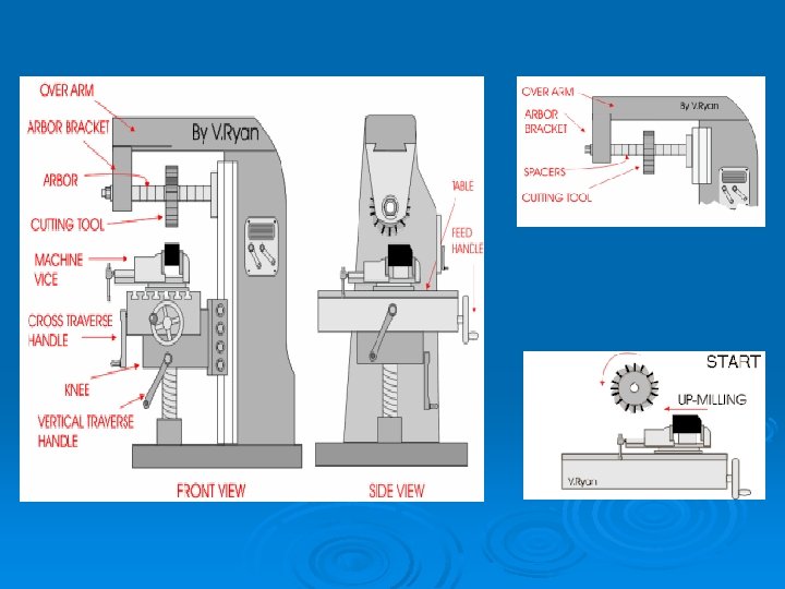
Universal horizontal milling machines: ~ Difference from plain horizontal machine is addition of table swivel housing. -Located between table and saddle. -Permits table to be swiveled 45º in either direction in a horizontal plane. ~ Used for milling of helical grooves in twist drills, milling cutters, and gears. • Parts of the Universal Horizontal Milling Machines: ~ Base give support and rigidity to machine and acts as reservoir for the cutting fluids. ~ Column face is precision-machined and scraped section used to support and guide knee when moved vertically. ~ Knee is attached to the column face and moved vertically. It houses the feed mechanism. •
~ Table rests on guideways in the saddle and travels longitudinally in a horizontal plane. It supports the vise and the work. ~ Spindle provides the drive for arbors, cutters, and attachments used on a milling machine. ~ Overarm provides for correct alignment and support of arbor and various attachments. It can be adjusted and locked in various positions. ~ Arbor support is fitted to the overarm and can be clamped at any location on the overarm. Its purpose is to align and support various arbors and attachments.
Figure 3. 17: Universal Horizontal Milling Machine
• Horizontal Milling Machine Accessories: ~ Fixtures is a work-holding device fastened to table of a machine, such as a rotary table. ~ Attachments divided into three categories: -they are attach to the spindle and column of the machine such as vertical milling, rack milling, and slotting attachments. These attachments are designed to increase the versatility of the machine. -arbors, collects, and adapters, which are designed to hold standard cutters. Figure 3. 17: Arbors, Collects, and Adapters.
~ Mounting and Removing a Milling Machine Arbor and Cutter. The cutter can be changed very easily. The arbor bracket is removed by loosening nuts and bolts that hold the arbor firmly in position. The arbor can be slid off the over arm. The spacers are then removed as well as the original cutter. The new cutter is placed in position, spacers slid back onto the arbor and the arbor bracket tightened back in position.
-those designed to hold the workpiece, , such as a vise, a rotary table, and an indexing, or dividing, head. Figure 3. 18: A plain vise, Swivel Vise, and Universal Vise
1. 3. 2 Horizontal Milling Cutter • The proper selection, use, and care of milling cutters must be practiced if the best results are to be achieved with the milling machine. • Cutter qualities: ~ must be harder than the metal being machined. ~ strong enough to withstand pressures developed during the cutting operation. ~ tough to resist the shock resulting from the contact of the tooth with the work. ~ able to resist the heat and abrasion of the cutting process. • Most milling cutters are made of high speed steel (HSS) or cemented-carbide.
HSS cutters: ~ Consist of iron with various amounts of carbon (hardening agent), tungsten and molybdenum (enable steel to retain hardness up to red heat), chromium (increase toughness and wear resistance), and vanadium (increase tensile strength). • Cemented carbide cutters: ~ More expensive and 3 to 10 time faster than high speed steel cutter. ~ cemented carbide tips brazed to a steel body or inserts may be held in place by means of locking or clamping device. • Figure 3. 19: Cemented carbide tips and inserts
• (c) Types of Horizontal Milling Cutter: ~ Plain Milling Cutters – most widely used, which is a cylinder of high-speed steel with teeth cut on periphery to produce a flat surface. These cutters have several types, as shown in Figure 3. 20: Plain(d) milling cutters: (a) light-duty; (b) light-duty helical; (c) heavy-duty; (d) high-helix
~ Side Milling Cutters – narrow cylindrical milling cutters with teeth on the periphery to produce cutting slots, face and straddle milling operations. These cutters have several types, as shown in Figure 3. 21. (a) (b) (c) Figure 3. 21: Side milling cutters: (a) straight teeth; (b) staggered teeth; (c) half-side
~ Face Milling Cutters – generally over 6 in. (150 mm) in diameter and have inserted teeth. Most cutting action occurs at beveled corners and periphery of cutter to produce the roughing and finishing cuts in one pass. Cutters under 6 in. (150 mm) are called shell end mills and there are solid, multiple-tooth cutters with teeth on face and periphery. Usually held on stub arbor, which may be threaded or use a key in the shank to drive cutter. (b) Figure 3. 22: Face milling cutters: (a) face cutter; (b) shell end mill and adapter (a)
~ Angular Cutters – have teeth neither parallel nor perpendicular to the cutting axis and used for milling angular surfaces, such as grooves, serrations, chamfers, and reamer teeth. They divided into two groups its single-angle and double-angle milling cutters. Figure 3. 23: Angular cutters: (a) single-angle ; (b) double-angle (a) (b)
~ Formed Cutters – incorporate the exact shape of the part to produce. Examples of formed-relieved cutters are concave, convex, and gear cutters. Figure 3. 24: Types of formed cutters: (a) concave; (b) convex; (c) gear tooth
~ End Mills – have cutting teeth on the end as well as on the periphery and are fitted to the spindle by a suitable adapter. They are two types such as solid end mill, in which the shank and the cutter are integral, and the shell end mill, which, as previously stated, has s separate shank. ~ T-Slot Cutter – used to cut the wide horizontal groove at the bottom of a T-slot after the narrow vertical groove has been machined with an end mill. Consists of small side milling cutter with teeth on both sides and integral shank for mounting. Figure 3. 25: T-slot Cutter
~ Dovetail Cutter – similar to a single-angle milling cutter with an integral shank. They are used to form the sides of a dovetail after the tongue or the groove has been machined with another suitable cutter. Figure 3. 26: Dovetail Cutter ~ Woodruff Keyseat Cutter – similar in design to plain and side milling cutters. Used for milling semi-cylindrical keyseats in shafts. Designated by number system. Figure 3. 27: Dovetail Cutter
~ Flycutters - Single-pointed cutting tool with cutting end ground to desired shape. Mounted in special adapter or arbor. Figure 3. 28: A Flycutter
Figure 3. 29: Types of Horizontal Milling Operations