Shaper Machine Introduction It is reciprocating type of












- Slides: 49
Shaper Machine
Introduction • It is reciprocating type of machine tool used for producing flat surfaces. • Surfaces may be horizontal, vertical or inclined. • Modern shapers can produce contoured surfaces. • It uses reciprocating straight line motion of the tool and a perpendicular feed of the job or the tool. • By moving the work piece across the path of the reciprocating tool, a flat surface is generated regardless of the shape of the tool.
Principle
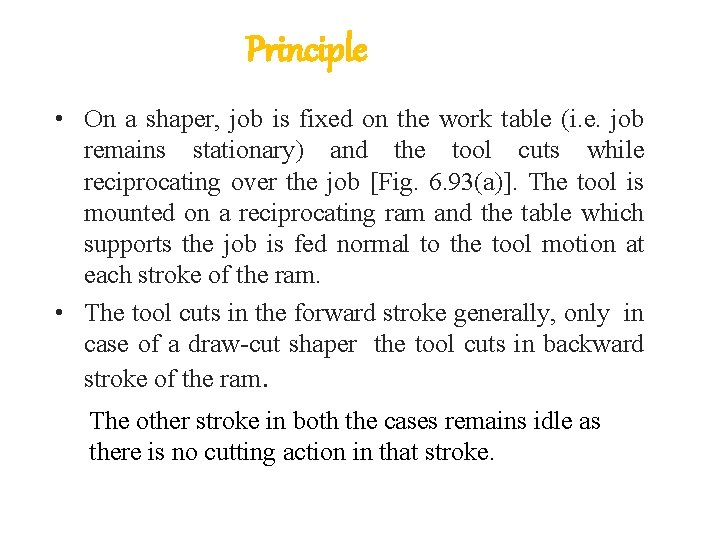
Principle • On a shaper, job is fixed on the work table (i. e. job remains stationary) and the tool cuts while reciprocating over the job [Fig. 6. 93(a)]. The tool is mounted on a reciprocating ram and the table which supports the job is fed normal to the tool motion at each stroke of the ram. • The tool cuts in the forward stroke generally, only in case of a draw-cut shaper the tool cuts in backward stroke of the ram. The other stroke in both the cases remains idle as there is no cutting action in that stroke.
Classification of Shaper • According to the type of mechanism used for giving reciprocating motion to the ram a) Crank type b) Gear type c) Hydraulic type • According to type of ram a) Horizontal b) Vertical c) Travelling head type
Classification of Shaper • According to the design of table • a) Standard shaper b) Universal shaper • According to the cutting stroke • a) Push type • b) Draw type
Figture OF Shaper Machine
Principal Parts • Base: Shaper base is a heavy structure of cast iron. It supports all the other parts and assemblies (described in the following). It resists vibration and high compressive loads being of cast iron. Base is bolted down to the shop floor through foundation bolts.
Principal Parts • Column: It is a box structure of cast iron and houses the operating mechanisms of the machine. It also provides support for other parts of the machine, such as ram, cross-rail, etc. Column consists of two vertical walls which are supported on the shaper base.
Principal Parts • Cross-rail: The cross-rail block is mounted on the front two vertical guide ways of the column. The cross-rail block has two parallel horizontal guide ways(K) in the vertical plane and perpendicular to the axis of ram.
Principal Parts • Saddle: The saddle moves on the cross-rail block and carries the table (or work table) on it such that crosswise movement of the saddle by rotating the cross feed screw by hand or by power makes the table to move sideways.
Principal Parts • Table: The table is firmly connected on to the saddle. It gets its crosswise and vertical movements from the saddle and cross-rail, respectively (as explained above in case of saddle). Table is a box structure casting having T-slots both on top and sides for clamping the job.
Principal Parts • Ram: It is the reciprocating member with tool head mounted on its front face. Ram is semi-cylindrical in form with rigid structure heavily ribbed inside. It slides on two accurately machined guide ways (dovetail type) made on the top of column walls. The ram is connected to the reciprocating mechanism (quick return) housed inside the hollow of the column. the ram is housed the mechanism for altering the ram positions with respect to the job.
Principal Parts
Principal Parts • Tool head or shaper head: It is mounted at the front end of ram and has the provision of being swiveled in any direction for shaping angular surfaces. The tool is held in tool post.
MECHANISM OF SHAPING MACHINE Quick-return mechanisms • These types of machine tool are of rectilinear cutting motion therefore, the rotary motion of the drive is converted into reciprocating motion. • The metal is removed in the forward cutting stroke, while the return stroke goes idle and no metal is removed during this period. • The cutting mechanism is so designed that it moves at a comparatively slower speed during forward cutting stroke, whereas during the return stroke it allow the ram to move at a faster speed to reduce the idle return time. This mechanism is known as quick return mechanism.
The reciprocating movement of the ram and the quick return mechanism of the machine are generally obtained by anyone of the following methods: 1. Lever rocker arm mechanism (shaper). 2. Slider crank mechanism (slotter). 3. With worth quick return mechanism (shaper and slotter). 4. Hydraulic system ( all the 3 types). 5. Variable speed reversible motor (slotter and planer). 6. Rack and pinion mechanism (planer).
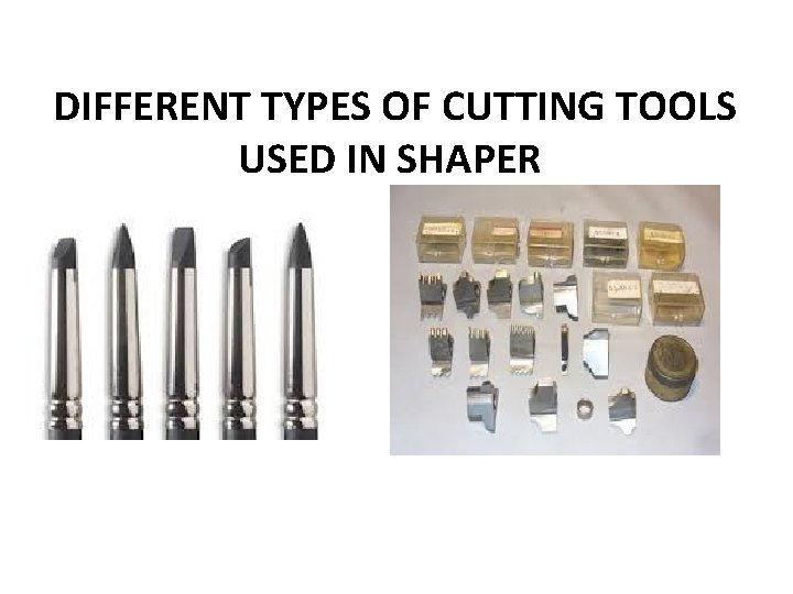
DIFFERENT TYPES OF CUTTING TOOLS USED IN SHAPER
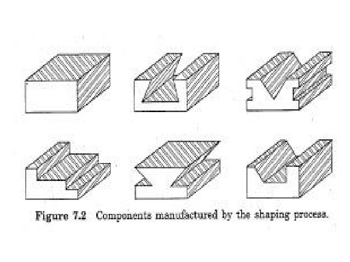
OPERATIONS PERFORMED ON SHAPER Ø Operations involved in shaping a rectangular job on shaper. Ø Machining a thin job on shaper. Ø Cutting an angle on a large job. Ø Cutting a dovetail bearing on a shaper. Ø Shaping a V or keyway in a block. Ø Shaping regularly angled component. Ø Shaping an irregularly curved surface. Ø Cutting a keyway on a shaper when the keyway does not extend the entire length of the shaft. Ø Machining angular surfaces on shapers. Ø Sequence of machining sides of a rectangular piece square and parallel.
ADVANTAGES OF SHAPERS • The single point cutting tools used in shapers are inexpensive, these tools can be easily grounded to any desirable shape. • The simplicity and ease of holding work, its easy adjustment, and the simple tool give the shaper its great flexibility. • Shaper set up is very quick and easy and can be readily changed from one job to another. • Thin or fragile jobs can be conviniently machined on shapers because of lower cutting forces.
LIMITATIONS q. Shape only one piece of stock at a time. q. Not suitable for large parts as stroke length is limited and overhanging of the ram. q. Shape stock only if longer than 25 cm (10 in).
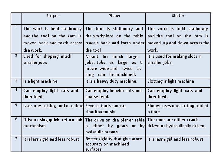
1 Shaper Planer Slotter The work is held stationary and the tool on the ram is moved back and forth across the work. Used for shaping much smaller jobs The work is held stationary and the tool on the ram is moved up and down across the work. It is used for making slots in smaller jobs. Can employ light cuts and finer feed. 3 Is a light machine The tool is stationary and the workpiece on the table travels back and forth under the tool Meant for much larger jobs. Jobs as large as 6 metre wide and twice as long can be machined. It is a heavy duty machine. 4 Can employ light cuts and finer feed. Can employ heavier cuts and coarse feed. 5 Uses one cutting tool at a time Several tools can cut simultaneously. 6 Driven using quick- return link The drive on the planer table The rams are either crankmechanism is either by gears or by driven or hydraulically driven. hydraulic means It is less rigid and less robust Better rigidity that give more It is less rigid and less robust accuracy on machined surfaces. 2 7 Slotting is light machine Shaper uses one cutting tool at a time
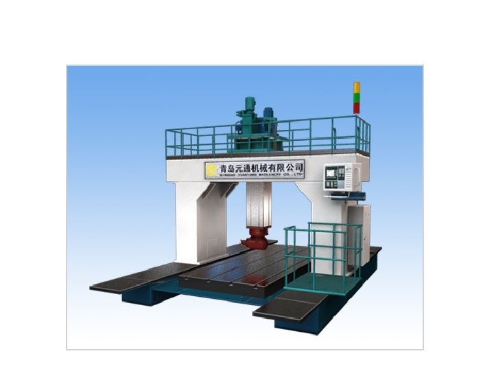
Planner Machine
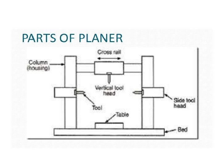
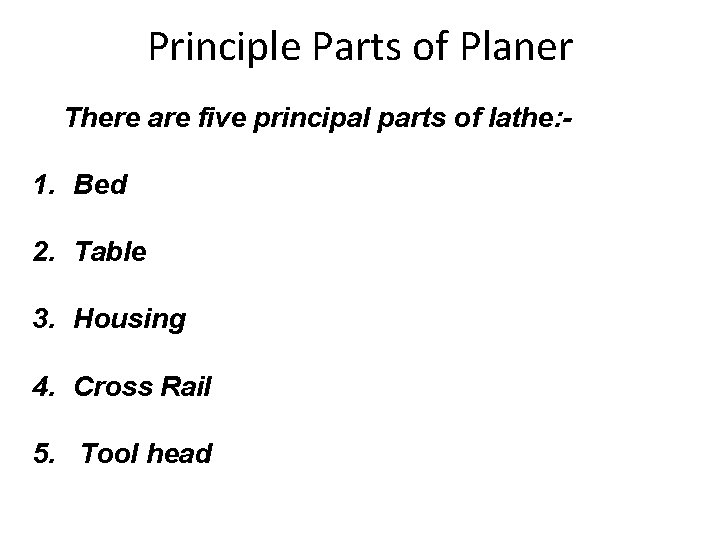
Principle Parts of Planer There are five principal parts of lathe: - 1. Bed 2. Table 3. Housing 4. Cross Rail 5. Tool head
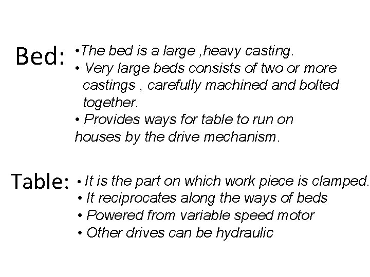
Bed: Table: • The bed is a large , heavy casting. • Very large beds consists of two or more castings , carefully machined and bolted together. • Provides ways for table to run on houses by the drive mechanism. • It is the part on which work piece is clamped. • It reciprocates along the ways of beds • Powered from variable speed motor • Other drives can be hydraulic
HOUSING: • They are rigid & upright column like casting. • Located near the centre on each side of the base. CROSS RAIL: • It is horizontal member supported on machined ways of upright column. • Vertical movement of cross rail allows to accommodate work piece of different heights.
Types Of Planer There are Five types of planers: - 1. Double Housing 2. Open slide 3. Pit Type Planer 4. Plate Planer
Double Housing Planer : - • Most commonly used planer machine. • One drawback-Limits the width of work piece due to presence of two housing on each side of bed.
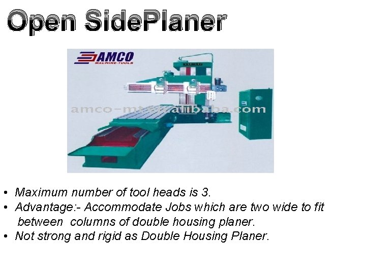
Open Side. Planer : - • Maximum number of tool heads is 3. • Advantage: - Accommodate Jobs which are two wide to fit between columns of double housing planer. • Not strong and rigid as Double Housing Planer.
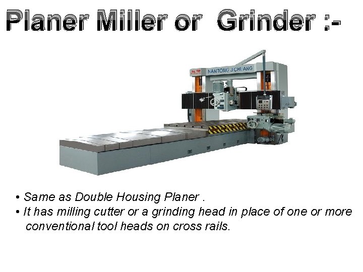
Planer Miller or Grinder : - • Same as Double Housing Planer. • It has milling cutter or a grinding head in place of one or more conventional tool heads on cross rails.
Pit type Planer : - • Used when work becomes extremely heavy. • Table is kept stationary and tool reciprocates. • Design is used to plane the largest kind of works. • It is convenient and economical to move machine than work piece
Plate planer : • Special purpose machine tool designed specially for squaring or leveling edges of heavy steel plates. • Job/table is stationary while tool and operator move bark and forth along the work for feed and cut. • The plate is clamped to a bed and the side mounted carriage is move back and forth.
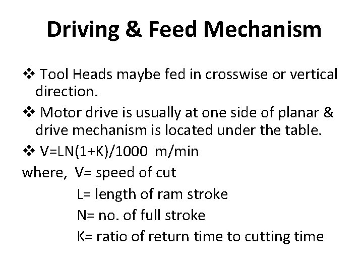
Driving & Feed Mechanism v Tool Heads maybe fed in crosswise or vertical direction. v Motor drive is usually at one side of planar & drive mechanism is located under the table. v V=LN(1+K)/1000 m/min where, V= speed of cut L= length of ram stroke N= no. of full stroke K= ratio of return time to cutting time
Work Holding Devices v. T-Bolts & Clamps (most jobs done by bolts & clamps) v Stop Pins (supports the work piece) v Toe Dogs (holding thick work piece) v. Vises (common work holding device) v Fixtures (special purpose work holding device)
Planar Drives • Reversible DC Motor Drive (this drive has advantage that speed of motor can be varied according to the field current supplied) • Hydraulic Drive (it is similar to that used for horizontal shaper. More than one hydraulic cylinder may be used to give wide range of speeds)
1 Slotting machine (SLOTTER)
2
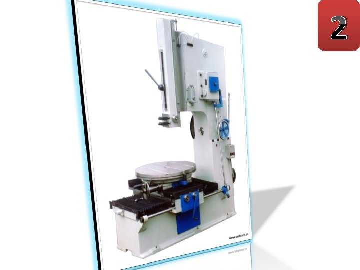
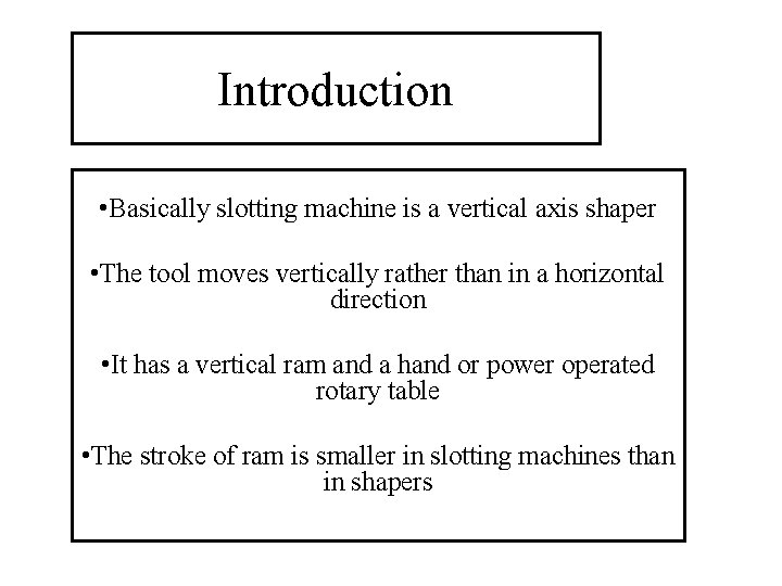
Introduction • Basically slotting machine is a vertical axis shaper • The tool moves vertically rather than in a horizontal direction • It has a vertical ram and a hand or power operated rotary table • The stroke of ram is smaller in slotting machines than in shapers
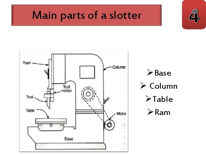
Main parts of a slotter ØBase Ø Column ØTable ØRam 4
ØBase 5 : It is also known as bed and it is a heavy cast iron construction’ It acts as a support for the column, the driving mechanism of ram, table and other fittings ØColumn: It is made of cast iron & it acts as a housing for the complete driving mechanism ØTable: usually a circular table is provided in slotter. Ø T –slots are provided on top of the table to clamp the work ØRam: it moves in vertical direction between the vertical guideways provided in front of the column ØThe ram supports the tool head to which the tool is attached & the cutting action takes place during the downward movement of the ram
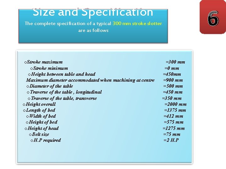
6 Size and Specification The complete specification of a typical 300 mm stroke slotter are as follows o. Stroke maximum o. Stroke minimum o. Height between table and head Maximum diameter accommodated when machining at centre o. Diameter of the table o. Traverse of the table , longitudinal o. Traverse of the table, transverse o. Height overall o. Length of bed o. Width of bed o. Height of head o. Belt size o. H. P required =300 mm =450 mm =900 mm =500 mm =450 mm =350 mm =2000 mm =1375 mm =412 mm =575 mm =1275 mm =2 H. P
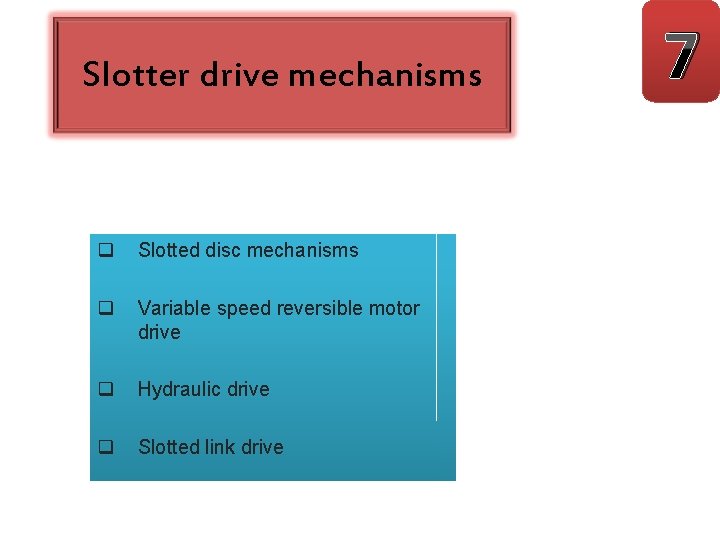
Slotter drive mechanisms q Slotted disc mechanisms q Variable speed reversible motor drive q Hydraulic drive q Slotted link drive 7
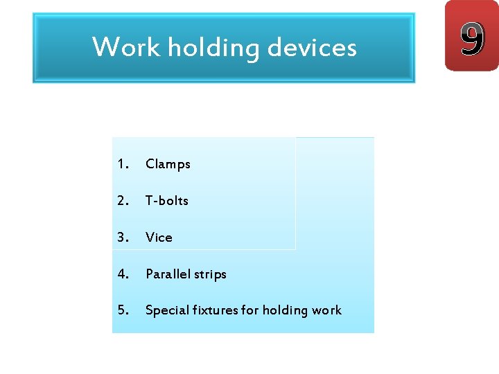
Work holding devices 1. Clamps 2. T-bolts 3. Vice 4. Parallel strips 5. Special fixtures for holding work 9
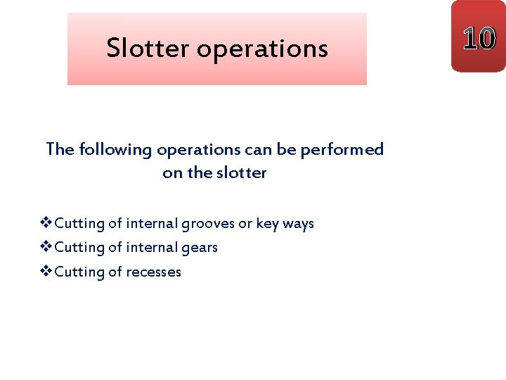
Slotter operations The following operations can be performed on the slotter v. Cutting of internal grooves or key ways v. Cutting of internal gears v. Cutting of recesses 10
Any doubts?