Milling Gear Cutting Presented By Bidve M A

Milling & Gear Cutting -Presented By Bidve M. A.

Introduction of Milling • It is defined as the machine tool in which rotating multi point cutter is used for removal of material from the work piece. • Due to multi point cutting edges with high speed of rotation, the rate of metal removal is very high. • On a spindle(arbor) of milling machine, it is possible to mount one or more number of cutters at a time for multiple operation.

Introduction of Milling

Principle of Milling • In milling machine the metal is cut by means of multitooth rotating cutter. • As the work moves against the cutting edge, a chip of metal is removed. • The speed of cutting tool and rate at which the work piece travels depends upon the material being machined.
 Horizontal milling machine.")
Classification of Milling Machine 1. According to position of Spindle a) Horizontal milling machine. b) Vertical milling machine. c) Special purpose milling machine. 2. According to Design a) Column and knee type milling machine. i) Hand milling machine. ii) Plain milling machine. iii) Universal milling machine. iv) Vertical milling machine. b) Fixed bed type milling machine. i) Simplex milling machine ii) Duplex milling machine iii) Triplex milling machine. c) Planer milling machine.
 Special type of milling machine i) Rotary table milling machine. ii) Planetary milling")
d) Special type of milling machine i) Rotary table milling machine. ii) Planetary milling machine. iii) Profiling milling machine. iv) Duplicating milling machine. v) Pantograph milling machine. vi) Tracer controlled milling machine.

Column & Knee Type
")
Column & Knee Type • This milling machine has two main structural elements. i) A column (main frame) ii) A knee(table) Column contains the spindle and its driving mechanism and knee moves vertically on the column. Six principle parts of these machines are as follows.

1. Base: The base on which the milling machine structure is built. 2. Column: It contains the spindle and its driving mechanism. 3. Overarm: It is mounted on the column which supports the other end of the arbor. 4. Knee: It is a structural member attached to the column which moves vertically on the column to mount work of various heights.

5. Saddle: It is mounted on the knee and which moves horizontally. 6. Table: It is mounted on saddle which moves at right angles to the saddle. Work is clamped on table. It is used for small and medium sized work in tool rooms and prototype shops. These machines are made both horizontal and vertical spindles.

Milling Cutters • • Plain Milling cutter. Side milling cutter. Angle milling cutter. Form milling cutter. End milling cutter. Metal slitting saw. Special application cutters.

Plain Milling cutters Helical Milling cutters

Characteristics • They are used to produce flat surfaces that are parallel to the axis of spindle. • Plain cutters upto 19 mm width have straight teeths. • Wider milling cutters have helical teeths. • Width upto 160 mm and diameter 16 to 160 mm.

Sr. No Type Feature Applications 1 Light Duty Width less than 19 mm Light slabbing cuts and shallow teeths are small cuts light cuts with fine feeds. 2 Heavy Duty Fewer teeth than light duty larger width Heavy duty work to remove large stock deeper cuts, coarse application 3 Helical Duty Helix angle 450 to 600 fewer teeth than above both types Profile milling work, smooth cutting action, for brass and soft steel machining.

Side Milling cutter

Characteristics • The teeth on the circumference do most of the cutting while those on the sides finish the side of cut to size. • The teeth may be either straight/ helical type. • Used for straddle milling in which more number of cutters are mounted on arbor. • Available from 50 to 200 mm in diameter and the width of cutter ranges from 5 to 32 mm.

Sr. No Type Feature Applications 1 Plain type Side teeths on both sides Straddle milling operation 2 Staggered teeth Alternate teeth with opposite helix angle Milling of deep, narrow slots or keyways on workpiece heavy duty face milling 3 Half side Helical teeths on one side only Straddle milling operation 4 Interlocking Two half side milling cutters Slot milling, bosses, etc are combined

Angle Milling cutters Single ended cutter Double ended cutter Characteristics: Used to machine other than 900

Sr. No Type Feature Applications 1 Single Angle One angular surface Milling of dovetails, notches available with 450 , 600 , etc on rachet wheel, etc. 2 Double Angle V- shaped teeths with both conical / angular surfaces V- grooves machining, cutting spiral grooves, etc

Form Milling cutters Convex formed cutter Concave formed cutter

Characteristics • They are provided with irregular profiles. • Available in 50 to 125 mm and width 1. 5 to 20 mm.

Sr. No Type Feature Applications 1 Concave Teeth curved inwards to form semicircle To produce concave shapes 2 Convex Teeth curved outwards to To produce convex shapes form semicircle 3 Corner rounding Teeth curved inwards to form quarter circle Cutting radius on the corners, edges of the work

End Milling cutters

Characteristics • Teeth on both side i. e. periphery and end. • Teeth may be straight/ helical. • Size from 3 mm to 40 mm diameter.

Sr. No Type Feature Applications 1 Taper shank The end has tapered shank double/ multiple fluted Longer cutting life and better surface finishing, slots, keyways. 2 Straight shanks for mounting, straight/ helical. Slots, keyways, pockets. 3 Shell end mill Teeths larger/ heavier, multiflute Face milling operation.

Metal Slitting saw

Characteristics • Thin upto 5 mm thick. • Sides slightly dished for clearance. • More teeths than other milling cutters.

Sr. No Type Feature Applications 1 Plain type Thinner in costruction Ordinary slotting and cutoff 2 Staggered type Similar to staggered type, width 6. 5 to 7 mm Heavy sawing in steel

Special Application cutters • T-slot cutters: They are a special form of mills for producing T-slots. In producing T-slots a vertical groove must first be made with a slotting milling or an end milling cutter than T-slot cutter is then used to complete the slot. Applications: Producing T-slot in machine tool worktables such as drilling machines.

• Woodruff key slot milling cutter: It is slot milling cutter with pointed tooth having sides slightly concave used for cutting keyways and seatings in shafts for keys made on the woodruff principle.

• Fly cutter: It consists of a single point cutting tool attached to the end of the arbor. Sometimes in a heavy disc that acts like a flywheel. They are mainly used in experimental shops or in tool room works. They are primarily used for few pieces are to be made.

• Thread milling cutters: They are parallel sided cutter with spiral flutes. They are used to produce worm and acme threads and they have straight or taper shanks. • They are available in diameters 16 to 25 mm and the length of threaded portion varies from 16 to 40 mm.

Milling Operation • • Plain Milling Side Milling Straddle Milling Gang Milling Face Milling Slot Milling Saw Milling Form Milling Angular Milling End Milling Profile Milling Keyway, Groove Milling Helical Milling Cam Milling, Thread Milling

Slab or Plain Milling • This milling operation produces plain or flat horizontal surface parallel to the axis of rotation of the plain/ slab milling cutter. • The plain milling cutter is held in the milling arbor and workpiece is mounted firmly in the vice or table of milling machine. • The depth of cut is adjusted by rotating the vertical feed screw of the table.

Side Milling • It is the milling operation to produce a flat vertical surface on the side of workpiece. • The side milling cutter is used to machine vertical surface. • The two parallel sides of the workpiece are machined by two side milling cutters as shown in fig.

End Milling • In this operation an end mill cutter is used to machine and produce a flat surface or a pair of parallel flat surfaces. • This is the operation consists of combination of peripheral and face milling operation. • It is used to produce flat surfaces parallel to or perpendicular to the axis of cutter.

Straddle Milling • The straddle is the milling operation of flat vertical surfaces on both sides of workpiece by using two side milling cutters mounted on same arbor. • The distance between two cutters is correctly adjusted by using suitable spacing collars. • It is commonly used to produce square or hexagonal surfaces.

Gang Milling • It is the operation in which number of milling cutters are mounted on arbor(gang of cutters) to make it possible to machine several surfaces in one pass. • It is modification of straddle milling with more number of cutters in the machining. • The cutters may have same or different diameters mounted on the arbor of machine.

Gang Milling • This operation saves much of machining time and widely used in repetitive work. • The cutting speed of a gang of cutters is calculated from the cutter of the largest diameter.

Face Milling • It is performed by a face milling cutter rotated about an axis perpendicular to the work surface. • The machine surface is parallel to the face of the cutter. • A face cutter if used on a vertical machine to produce horizontal flat surface and if used on horizontal machine produce vertical surface.

Slot Milling • In this operation slotting cutter is used to produce the slot of given width corresponding to cutter size. • The cutter is placed exactly at the centre line of the workpiece and then cut is taken. • Applications: Slotted head screw, T-slot milling machine, Key way slot in shaft, pulley, etc.

Slitting Operation • Slitting operation makes use of slitting saw to cut stock into various widths for the production of flat gages, templates, etc. • It is suitable for narrow slots or grooves in a workpiece. • It can also be used for complete parting off operation.

Form Milling • It is the operation of producing concave, convex or any other irregular shape by using form cutter. • The shape of cutting teeth of the form cutter will same as that of the profile to be generated on the workpiece surface. • The formed surface is checked by a template gauge.

Angular Milling • It is the operation of machining a flat surface on a job at an angle(other than right angle) to the axis of the milling machine table. • Examples: V-block, dovetails, etc.

Thread Milling • This operation is used to cut threads and worm gears, etc by means of thread milling cutters. • It is mounted on arbor to cut coarse pitch threads while group of thread milling cutters in a row are mounted to cut fine pitch threads on short length jobs. • It is used for long screwed points such as lead screws, worms, etc.

Up Milling Process • It is also called as conventional milling process. • In this method the milling cutter is rotated against the direction in which the workpiece travels.

Up Milling • The thickness of chip is minimum at the beginning of the cut and it reaches to the maximum when cut finish. As the chip thickness is not uniform. • The cutting force is directed upwards and tends to lift the workpiece from the fixtures. • In up milling it is difficult to pour coolant at the contact of cutter with the workpiece. • The surface milled by up milling appears to be slightly wavy and cutter spoils the work surface.

Down Milling Process • It is also called climb milling as cutter climbs on the workpiece surface. • In this process milling cutter is rotated in the same direction in which the workpiece travels.

Down Milling Process • The thickness of the chip is maximum when the tooth begins its cut and it reaches to the minimum when cut finish. • The cutting force is directed downwards and tends to seat the work firmly in the work holding devices. • The coolants can be poured directly at the cutting zone easily. • The surface finish by down milling was smooth.

Difference between Up Milling Down Milling Point Up Milling Down Milling Cutter Direction Against the direction of workpiece travel(feed) Same in the direction of the workpiece. Chip at beginning Minimum Maximum Removal of Metal Starts after travels of minute distance. Starts immediately. Cutting Force Causes lifting of the workpiece. It causes the workpiece to seat firmly. Cutting Chips Difficult for disposal may affect surface finish. Easy disposed off and better surface finish Coolant application Difficult to pour at cutting zone. Easy to pour coolant at cutting Zone.

Gear Cutting • A gear is a toothed wheel which has evenly spaced tooths on its periphery. • The gear when meshed with other gears transmits motion from one point to another. • Gear also transmits motion from one shaft to another. • With the ever growing demand for higher speeds, quieter running of the machines, the gear manufacturing is required.
 Sand casting: Rough and inaccurate gears ii) Die")
Gear Manufacturing Method 1. Casting: i) Sand casting: Rough and inaccurate gears ii) Die casting: Accurate and better surface iii) Investment Casting: Accurate and better 2. Stamping: Gears in clocks, watches , meters 3. Powder metallurgy: High quality gears 4. Extrusion: Gears from brass, bronze, Al and Mg 5. Plastic moulding: Gears used in toys. 6. Rolling process: Worm and Splines 7. Machining process: With using cutting tool.

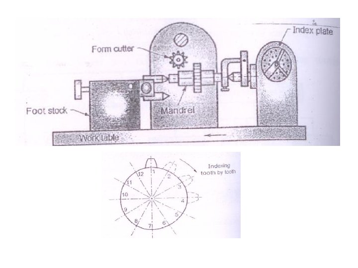
Gear cutting by Formed Cutter Method • The majority of gears which are used for transmitting power with high accuracy are made by machining method. • The form cutting is one of the machining process and makes use of gear cutter has the same form or shape between two adjacent teeth. • This method is performed on milling machines with the help of indexing.

Multiple gear tooth form cutting • In this method , it will cut all the tooth spaces by using number of cutting tools equal to the number of teeths in the gear. • It increases rate of machining the gears. • The gear shaping cutter head used in this method.

Template method of cutting gears • In this method the form of the gear tooth is controlled by a template instead of a form tool. • The tool used is a single point cutting tool that is guided by a template. • This method is suitable for cutting large teeth which otherwise difficult with a formed cutter. • Large straight bevel gears are also cut by this method.

Dividing Head or Indexing Head • The gear is manufactured using gear blank mounted on a mandrel of milling machine. • The gear blank periphery is divided into number of equal parts as per number of teeths to be cut on. • On milling machine the gear tooths are produced one by one and gear blank is rotated through the given calculated angle. • This function of dividing the periphery of gear blank as per the number of teeths required and indexing it after each tooth cutting is done by special attachment. This special attachment is called as dividing head.

Plain or simple dividing head • The spindle may be turned through the desired angle and then clamped inserting the clamping lever pin into any one of the equally spaced holes or slots cut on the periphery of the index plate. • The work is mounted on the nose end of the spindle by a chuck or may be supported between the two centers. • The live center is fitted at the nose of spindle and the dead centre is held by the tailstock. • It may be used for indexing divisions of 2, 3, 4, 6, 8, 12 and 24 parts.

Universal Dividing Head • In plain dividing head the axis of the spindle is fixed but in universal dividing head the axis located in a angular positions and used to execute all forms of indexing that’s why the name indicates universal. • FUNCTIONS: 1. Setting of work in vertical, horizontal or in inclined position w. r. to table. 2. Turning the workpiece periodically through a given angle by indexing technique. 3. Imparting rotary motion to the workpiece for milling helical grooves.
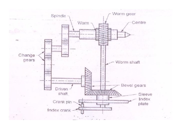

• The spring loaded crank pin is attached to the index crank and it is attached to the worm shaft. • The worm gear is fitted on the spindle which hold the workpiece at its front end by using centre. • The motion of the index crank is given to the workpiece through worm shaft mechanism. • An index plate is mounted on the sleeve which is loosely fitted on the worm shaft • The dividing head is provided with sector arms which eliminates the counting of holes on the index plate.

• The spindle is provided with a taper hole at the nose for mounting a live centre face plate or chuck can be mounted on nose outside threads. • The spindle is swivelled with the help swivelling block and can be clamped at desired position. • The graduated scale fitted on the body helps for angular setting. • The worm gear has 40 teeth and the worm is single threaded. When the crank rotates through 40 turns, the work rotates through 1/40 th of turn or through 90. • If the index pin is moved from one hole to the next hole in a 18 hole circle of the index plate, then spindle will rotate the workpiece through 1/40*1/18=1/720 of a revolution or throgh 0. 50.

Indexing • Defination: Indexing is the operation of dividing the periphery of a workpiece into any no of equal parts. • It is the operation which rotates the workpiece through a certain number of degrees or certain fraction part of a complete circle for the purpose of graduating or dividing the part.

Application • • • Cutting teeth on gear blanks. Milling a square, hexagon headed bolts. Cutting splines on shafts Cam milling Fluting drills, taps and reamers.

Method of indexing • • • Direct indexing Simple or Plain indexing Compound indexing Differential indexing Angular indexing

Direct Indexing • It is the simplest method of indexing and used only on workpiece that requires a small number of divisions such as square or hexagonal nuts, etc. • This type of indexing can be performed in both plain and universal dividing head. • When using universal dividing head, the worm and worm wheel are first disengaged. • The rapid index plate is fitted directly on the spindle. The plate has 24 holes and indexing pin can be pushed in the required number of hole for indexing.

• During indexing the pin is first taken out and the spindle is rotated by hand after the required position is reached it is again locked by the pin. • Since the index plate is fastened directly to the spindle, the rotation of the index plate rotates the spindle by same part of rotation. • Crank may be rotated to divide the periphery of the workpiece into the divisions 2, 3, 4, 6, 8, 12, and 24 parts which are factors of 24.

Example • Ex. For square headed bolt manufacturing indexing movement is Index crank movement =24/N N= 4 for square headed bolt Index movement =24/4 =6 Hence index plate to be moved by 6 holes after machining one side for 3 number of times to machine square headed bolt.

Simple or Plain Indexing • It is used when it is required to divide a circle into more number of parts then is possible by rapid indexing. • It is more accurate and suitable when more number of equal parts on the workpieces are to be produced. • The index plate is not fastened directly to the spindle. • Index plate 1= 15, 16, 17, 18, 19, 20 • Index plate 2= 21, 23, 27, 29, 31, 33 • Index plate 3= 37, 39, 41, 43, 47, 49

Example • Index for 10 divisions Index crank movement=40/N =40/10 =4 Index for 136 divisions Index crank movement=40/N =40/136 =5/17 The index plate 1 has 17 hole circle, so far each divisions turn the crank by 5 holes on a 17 hole circle.

Example • Index for 6 divisions Index crank movement=40/N =40/6 =6*2/3 2/3=2*10/3*10 =20/30 But there is no plate with hole 30 2/3=2*11/3*11 =22/33 The plate no 2 has 33 hole circle So for each division rotate the crank by 6 complete turns plus 22 holes on 33 hole circle of the index plate 2

Example • Index for 30 teeths on workpiece Index crank movement=40/N =40/30 =1*1/3 1/3=1*7/3*7 =7/21 So for indexing rotate the crank by one complete turn and 7 holes in 21 hole circle of the index plate 2.

Compound Indexing • It is used to obtain such number of divisions that are beyond the range of plain indexing system. • This method is called compound due to two steps are involved • Step 1: Turning the crank through a required number of spaces in one of the hole circles of the index plate in one direction similar to plain indexing • Step 2: Turning the index plate together with the index crank in the same direction or in opposite direction through the calculate number of spaces of another hole circle.

• The equation for compound indexing is 40/N=n 1/N 1+-n 2/N 2 Where N= the number of divisions required N 1= the hole circle used by crank pin N 2= the hole circle used by lock pin n 1= the hole spaces moved by the crank pin in N 1 hole circle n 2= the hole spaces moved by the crank pin in N 2 hole circle

Example • Index 69 divisions by compound indexing 40/N=n 1/N 1+-n 2/N 2 40/69=n 1/N 1+-n 2/N 2 Determine values of n 1, n 2, N 1, N 2 a)69=23 X 3 b)Choose random hole circle 23 and 33 c) Subtract the hole circle 33 -23=10 d) Factor the difference 10=2 X 5 e) 69 =23 X 3 10 = 2 X 5
 40=2 x 2 x 5 g) 23= 23 x 1 33= 3 x")
f) 40=2 x 2 x 5 g) 23= 23 x 1 33= 3 x 11 h) 69= 23 x 3 10= 2 x 5 -----------40= 2 x 2 x 2 x 5 23= 23 x 1 33= 3 x 11 N 1=23 and N 2=33 The all circle above the line cancelled hence 23&33 can be used for indexing
 Multiply uncancelled factors 2 x 2 x 1 x 11=44 It is the")
i) Multiply uncancelled factors 2 x 2 x 1 x 11=44 It is the number of hole spaces to be moved for indexing 40/69=44/23 -44/33 =1 x 21/23 -1 x 11/33 =21/23 -11/33 Hence index crank should move by 21 holes in 23 hole circle forward Index plate and crank together by 11 holes in 33 hole circle backward

Differential Indexing • The additional feature of differential indexing is that introduction of a gear train to connect the dividing head spindle to the index plate so that they may rotate either in the same or opposite directions. • Differential indexing is the same in principle as compound indexing but the difference is that the index plate is rotated by gearing. • It is used when the work has to be turned an amount that cannot be obtained by simple indexing.

• In this method, the index plate is unlocked and connected to a train of gears that receive their motion from the worm gear spindle.
 x 40/ A • Index crank movement=40/A")
Rule for differential indexing • Gear ratio=(A-N) x 40/ A • Index crank movement=40/A • Number of idlers Condition Type of gear train Required idler gear (A-N) Positive i) Simple gear train ii) Compound gear train One No need of idler gear (A-N) Negative i) Simple gear train ii) Compound gear train Two One
x")
Example • Index 83 divisions 40/N=40/83 Assume A=86 almost equal to 83 Gear ratio=(A-N)x 40/A =(86 -83)x 40/86 =3 x 40/86 =72/24 x 40/86 Driver gear= 72, 40 Driven gear= 24, 86 Index gear movement=40/86=20/43 The index crank will have to be moved by 20 holes in 43 hole circle for 83 times.

Angular Indexing • The method of indexing in which the spindle is rotated through a definite angle by turning the crank is called as angular indexing. • The work must be indexed through an angle rather than a certain number of divisions. • It can be used for drilling at fixed angular points using angular index plate. It saves time and simple to operate. • Index crank movement(degree)= Angular displacement of workpiece /9 • If the angular displacement is expressed in minutes then index crank can be calculated by dividing the angle by 540 and if expressed in second then dividing by 32400

Example • Index 500 Index crank movement=50/9=5 x 5/9 =5/9 x 2/2 =10/18 Hence to index 500, the crank is rotated through 5 turns and 10 holes on the 18 hole circle. -Index an angle 190 40’ = (19 x 60)+40=1180’(minutes) Index crank movement=1180/(9 x 60)=2 x 5/27 The index crank should be moved two complete turns and 5 holes of 27 hole circle.
x 60+48=260148’’ Index crank")
• Index an angle 72015’ 48’’ 72 x 60=4320’ (4320+15’)x 60+48=260148’’ Index crank movement=260148/32400 =8. 029

Gear Shaping • Gear shaping is the method of manufacturing Gears using shaping cutter on the machine known as gear shaper. There are two types of gear shaping. 1) Gear shaping using rack cutter 2) Gear shaping using a pinion cutter

• Advantages: 1. Only one cutter is needed to cut all gears of same pitch. 2. Gear shaper process is much faster than form cutter method. 3. Rate of production is higher because cutting action is continuous. 4. Most accurate tooth profile are generated by this method. Disadvantages: 1. Internal gears can not be produced by this method. 2. The rate of production is lower compared to gear hobbing process due to the indexing of the blank is required periodically. 3. Worm and worm wheels can not be produced by this process.

Gear shaping using rack cutter • In this process the cutter is rack type cutter, the gear blank is mounted on vertical spindle and cutter is mounted on the reciprocating spindle.

• The cutter has the form of basic rack for the gear to be generated. The cutter reciprocates along the width of the blank and cuts the metal only during the downward stroke or the cutting stroke, the return stroke being idle. • Advantages: 1. A single cutter of any given pitch can be used to cut gears. 2. The tooth profile generated has high accuracy. 3. The production rate is higher than formed cutter method.

Gear shaping using a pinion cutter • In this process hardened pinion cutter is used. The gear cutter receives reciprocating movement which is principle movement. • The reciprocating movement of cutter and blank rotate at the same pitch line velocity.

• The cutter reciprocates like a cutting tool in a standard shaper but at a rate of 50 to 450 strokes per minute. • The relative speed of rotation of the cutter and the gear is same as the gear to be cut. Advantages: 1. A single cutter can be used to cut spur gears of same pitch. 2. Internal gears can be produced by this method. 3. The rate of production is higher due to continuous cutting action. 4. The machine is simpler than rack type process.

Gear Hobbing • Hobbing is a process of generating a gear by means of a cutter called hob that revolves and cuts like a milling cutter. • A gear hob is a rotary cutting tool with teeth arranged along a helical thread. The thread has a shape of the involute gear tooth. • The flutes are cut across the spiral to create cutting edges at regular intervals. • A hob may have one, two or more threads forming multipoint cutter for faster cuts.

Principle • It is a process in which the gear is cut through a generating process by rotating the gear blank and the cutter called hob at the same time with a fixed gearing ratio between hob and gear blank. • The hob is mostly 75 to 150 mm diameter.

Gear hobbing process • Gear hobbing process has three operative motions. 1. Hob rotation 2. Hob feed 3. Gear blank rotation

1. The gear blank is first moved in towards the rotating hob until the proper depth is reached. 2. As soon as the proper depth is reached the hob cutter is fed across the face of the gear until the teeth are complete. Both gear and cutter hob rotates during the entire process. 3. The speeds of the two are so synchronized that the blank rotates through one pitch distance for each revolution of the hob. 4. The hob and the gear blank are fastened to shafts which are at right angles to each other, the axis

Types of hobbing methods 1. Climb Hobbing: In this method the direction of rotation of the hob coincides with the direction of work feed. The chip starts thin at the beginning and ends out thicker as the cut ends

2. Conventional hobbing: The hob rotates in a direction opposite to that in which the gear blank is fed. The chip starts thick at the beginning and ends out thinner as the cut ends.

Advantages 1. A high rate of production due to contineous cutting action in one direction. 2. It can be used for spur, helical, splines, chain, sprockets. 3. Quick to setup, economical for short/long runs. 4. Smooth cutting action makes accurate gears. 5. One hob can be used to cut spur/ helical gears of different angles. 6. Several gear blanks mounted on arbor can be hobbed simultaneously. 7. Setting and operation of hobbing machines is simpler. 8. Heat distributed evenly over the blank and the hob hence no overheating of hob and blank.

• Disadvantages: 1. Can not be used to cut internal gears. 2. Can not be used to cut near shoulders, flanges, etc. 3. Can not produce unsymmetrical shapes because of rotary cutter. Applications: For cutting spur gears, helical gears, worms, cams, sprockets, worm wheel, etc.

Difference between Gear Shaping and Gear Hobbing Point Gear Shaping Gear Hobbing Principle Reciprocating motion of the Generates teeths on gear by cutter based on shaping process. means of rotating cutter called as hob. Cutter used It uses rack cutter or pinion cutter It uses multipoint cutter known as hob Time required It requires more time than hobbing It is rapid, economical and highly productive. Internal Gear It can be used to produce internal gears also It can not generate internal gears. Types Rack cutter, pinion cutter Conventional and climb hobbing

Methods of gear finishing 1. 2. 3. 4. 5. 6. Gear shaving Gear grinding Gear burnishing Gear lapping Gear honing Gear tooth rounding

Gear Shaving • It is the finishing operation that removes small amounts of flanks of gear teeths. • It helps to improve small errors in tooth spacing, Helix angle, Tooth profile error and concentricity. • The function of gear shaving is that it finish on tooth surfaces, eliminate tooth end load concentration, Reduce gear noise, Increase load carrying capacity. • Gear shaving is of two types 1. Rack shaving 2. Rotary shaving.

Rack Shaving • In this method a rack type shaving tool is reciprocated under the gear and in feed is given at the end of each stroke. • This gear is suitable for gears of 150 mm maximum diameter.

Rotary Shaving • In this method gear shaving cutter is used which has grooves cut across the flanks in the planes at right angles to the axis of the cutter.

Gear Grinding • Gear grinding is gear finishing process in which special shape grinding wheel is used for finishing of heat treated gears. • Hardened heat treated gears are difficult to finish by other methods hence they are finished by gear grinding. 1. Generation grinding 2. Thread wheel grinding 3. Form wheel grinding

Generation Grinding • This method is used for grinding of spiral gears and hypoid gears. In this method two saucer shaped grinding wheels are used • The work gear is mounted on arbor or between centre and provided rotary motion to them about their axis. The reciprocating motion is given in the lateral direction for gear finishing.

Thread wheel grinding • In this method grinding wheel on which helical thread has been developed is used for gear grinding. • The gear finishing occurs due to rotation of the grinding wheel and work gear in mesh and wheel is transversed axially across the gear face.

• Spur and helical gears upto 500 mm in diameter can be ground in machines using a threaded wheel. • The advantage of this method are accuracy, speed and easy for changes in the tooth design. • The method has limitations that grinder is complicated sensitive and special skills are to be needed for the operator.

Form Wheel Grinding • In this method, the shape of the grinding wheel is similar to gear tooth spaces. • The grinding wheel passed through a tooth space to grind to root depth the left side of one tooth and the right side of the next tooth at the same time. • The grinding wheel rotates about its axis and one tooth is ground at a time.

Gear Burnishing • This method is used for improving the surface finish and uniformity of gears after cutting and prior to hardening(heat treatment) • The burnishing gear having hard, smooth and highly accurate cutting tooths is used for finishing. • The unhardened work gear is rolled with large application of lubricant(but without abrasive) in mesh with one or several burnishing gears. • The pressure of the burnishing gear tooths on the surfaces of the teeth of the work gear has work hardening effect and smooths out all the irregularities. • Burnishing will not correct tooth profile error or pitch of the gear. • This method is applicable for gears with less accuracy as well as gears not subjected to heat treatment processes.
- Slides: 109