Interconnection Networks Topology Prof Natalie Enright Jerger Topology




















- Slides: 56
Interconnection Networks: Topology Prof. Natalie Enright Jerger
Topology Overview • Definition: determines arrangement of channels and nodes in network – Analogous to road map • Often first step in network design • Significant impact on network cost-performance – Determines number of hops • Latency • Network energy consumption – Implementation complexity • Node degree • Ease of layout Fall 2014 ECE 1749 H: Interconnection Networks (Enright Jerger) 2
ABSTRACT METRICS Fall 2014 ECE 1749 H: Interconnection Networks (Enright Jerger) 3
Abstract Metrics • Use metrics to evaluate performance and cost of topology • Also influenced by routing/flow control – At this stage • Assume ideal routing (perfect load balancing) • Assume ideal flow control (no idle cycles on any channel) Fall 2014 ECE 1749 H: Interconnection Networks (Enright Jerger) 4
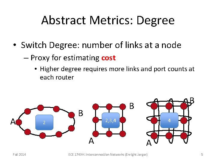
Abstract Metrics: Degree • Switch Degree: number of links at a node – Proxy for estimating cost • Higher degree requires more links and port counts at each router A B B 2, 3, 4 2 A Fall 2014 B 4 A ECE 1749 H: Interconnection Networks (Enright Jerger) 5
Abstract Metrics: Hop Count • Path: ordered set of channels between source and destination • Hop Count: number of hops a message takes from source to destination – Simple, useful proxy for network latency • Every node, link incurs some propagation delay even when no contention • Minimal hop count: smallest hop count connecting two nodes Fall 2014 ECE 1749 H: Interconnection Networks (Enright Jerger) 6
Hop Count • Network diameter: large min hop count in network • Average minimum hop count: average across all src/dst pairs – Implementation may incorporate non-minimal paths • Increases average hop count Fall 2014 ECE 1749 H: Interconnection Networks (Enright Jerger) 7
Hop Count B B A A Max = 4 Avg = 2. 2 B Max = 4 1. 77 A Max = 2 1. 33 • Uniform random traffic – Ring > Mesh > Torus • Derivations later Fall 2014 ECE 1749 H: Interconnection Networks (Enright Jerger) 8
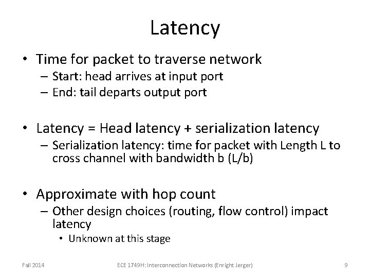
Latency • Time for packet to traverse network – Start: head arrives at input port – End: tail departs output port • Latency = Head latency + serialization latency – Serialization latency: time for packet with Length L to cross channel with bandwidth b (L/b) • Approximate with hop count – Other design choices (routing, flow control) impact latency • Unknown at this stage Fall 2014 ECE 1749 H: Interconnection Networks (Enright Jerger) 9
Abstract Metrics: Maximum Channel Load • Estimate max bandwidth the network can support – Max bits per second (bps) that can be injected by every node before it saturates • Saturation: network cannot accept any more traffic – Determine most congested link • For given traffic pattern • Will limit overall network bandwidth • Estimate load on this channel Fall 2014 ECE 1749 H: Interconnection Networks (Enright Jerger) 10
Maximum Channel Load • Preliminary – Don’t know specifics of link yet – Define relative to injection load • Channel load of 2 – Channel is loaded with twice injection bandwidth – If each node injects a flit every cycle • 2 flits will want to traverse bottleneck channel every cycle • If bottleneck channel can only handle 1 flit per cycle – Max network bandwidth is ½ link bandwidth – A flit can be injected every other cycle Fall 2014 ECE 1749 H: Interconnection Networks (Enright Jerger) 11
Maximum Channel Load Example A B E F C D G H • Uniform random – Every node has equal probability of sending to every node • Identify bottleneck channel • Half of traffic from every node will cross bottleneck channel – 8 x½=4 • Network saturates at ¼ injection bandwidth Fall 2014 ECE 1749 H: Interconnection Networks (Enright Jerger) 12
Bisection Bandwidth • Common off-chip metric – Proxy for cost – Amount of global wiring that will be necessary – Less useful for on-chip • Global on-chip wiring considered abundant • Cuts: partition all the nodes into two disjoint sets – Bandwidth of a cut • Bisection – A cut which divides all nodes into (nearly) half – Channel bisection min. channel count over all bisections – Bisection bandwidth min. bandwidth over all bisections • With uniform traffic – ½ of traffic crosses bisection Fall 2014 ECE 1749 H: Interconnection Networks (Enright Jerger) 13
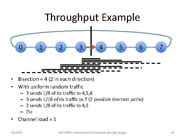
Throughput Example 0 1 2 3 4 5 6 7 • Bisection = 4 (2 in each direction) • With uniform random traffic – – 3 sends 1/8 of its traffic to 4, 5, 6 3 sends 1/16 of its traffic to 7 (2 possible shortest paths) 2 sends 1/8 of its traffic to 4, 5 Etc • Channel load = 1 Fall 2014 ECE 1749 H: Interconnection Networks (Enright Jerger) 14
Path Diversity • Multiple shortest paths between source/destination pair (R) • Fault tolerance • Better load balancing in network • Routing algorithm should be able to exploit path diversity A RA-B = 1 B B RA-B = 6 A Fall 2014 B ECE 1749 H: Interconnection Networks (Enright Jerger) RA-B = 2 A 15
NETWORK EVALUATION Fall 2014 ECE 1749 H: Interconnection Networks (Enright Jerger) 16
Evaluating Networks • Analytical and theoretical analysis – E. g. mathematical derivations of max channel load – Analytical models for power (DSENT) • Simulation-based analysis – Network-only simulation with synthetic traffic patterns – Full system simulation with real application benchmarks • Hardware implementation – HDL implementation to measure power, area, frequency etc. • Measurement on real hardware – Profiling and analyzing communication Fall 2014 ECE 1749 H: Interconnection Networks (Enright Jerger) 17
Evaluating Topologies • Important to consider traffic pattern • Talked about system architecture impact on traffic • If actual traffic pattern unknown – Synthetic traffic patterns • Evaluate common scenarios • Stress test network • Derive various properties of network Fall 2014 ECE 1749 H: Interconnection Networks (Enright Jerger) 18
Traffic Patterns • Historically derived from particular applications of interest – Spatial distribution – Matrix Transpose traffic pattern • di = si+b/2 mod b • b-bit address, di: ith bit of destination Fall 2014 19
Traffic Patterns Examples • Fast Fourier Transform (FFT) or sorting application shuffle permutation • Fluid dynamics neighbor patterns Shuffle: di = si-1 mod b Fall 2014 Neighbor: dx = sx+ 1 mod k ECE 1749 H: Interconnection Networks (Enright Jerger) 20
Traffic Patterns (3) • Uniform random – Each source equally likely to communication with each destination – Most commonly used traffic pattern • Very benign • Traffic is uniformly distributed – Balances load even if topology/routing algorithm has very poor load balancing – Need to be careful – But can be good for debugging/verifying implementation • Well-understood pattern Fall 2014 ECE 1749 H: Interconnection Networks (Enright Jerger) 21
Stress-testing Network • Uniform random can make bad topologies look good • Permutation traffic will stress-test the network – Many types of permutation (ex: shuffle, transpose, neighbor) – Each source sends all traffic to single destination – Concentration of load on individual pairs • Stresses load balancing Fall 2014 ECE 1749 H: Interconnection Networks (Enright Jerger) 22
Traffic Patterns • For topology/routing discussion – Focus on spatial distribution • Traffic patterns also have temporal aspects – Bursty behavior – Important to capture temporal behavior as well • Motivate need for new traffic patterns Fall 2014 ECE 1749 H: Interconnection Networks (Enright Jerger) 23
Full System Simulation Full System Simulator Application Processor No. C Simulator Packets Sent Cache No. C Disk Other Components Feedback! Packets Arrived Accurate But Slow Fall 2014 ECE 1749 H: Interconnection Networks (Enright Jerger) 24
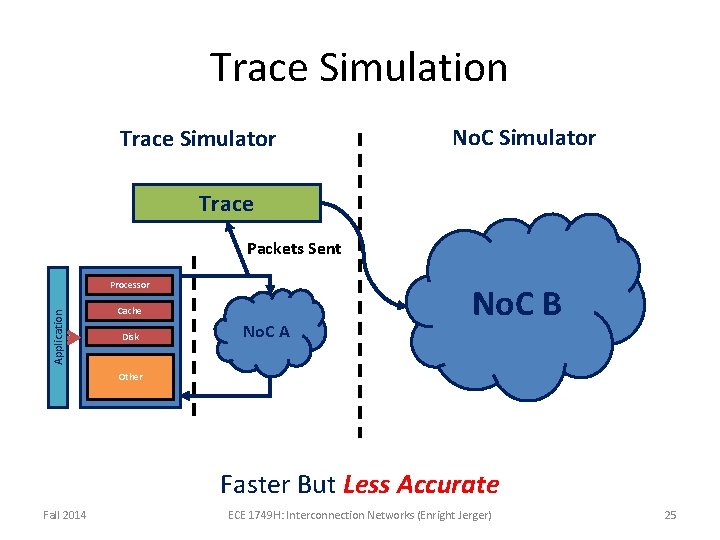
Trace Simulation Trace Simulator No. C Simulator Trace Packets Sent Application Processor Cache Disk No. C A No. C B Other Faster But Less Accurate Fall 2014 ECE 1749 H: Interconnection Networks (Enright Jerger) 25
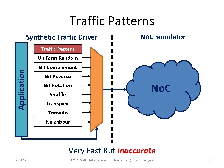
Traffic Patterns Synthetic Traffic Driver No. C Simulator Traffic Pattern Application Uniform Random Bit Complement Bit Reverse Bit Rotation Shuffle No. C Transpose Tornado Neighbour Very Fast But Inaccurate Fall 2014 ECE 1749 H: Interconnection Networks (Enright Jerger) 26
COMMON TOPOLOGIES Fall 2014 ECE 1749 H: Interconnection Networks (Enright Jerger) 27
Types of Topologies • Focus on switched topologies – Alternatives: bus and crossbar – Bus • Connects a set of components to a single shared channel • Effective broadcast medium – Crossbar • Directly connects n inputs to m outputs without intermediate stages • Fully connected, single hop network • Component of routers Fall 2014 ECE 1749 H: Interconnection Networks (Enright Jerger) 28
Types of Topologies • Direct – Each router is associated with a terminal node – All routers are sources and destinations of traffic • Indirect – Routers are distinct from terminal nodes – Terminal nodes can source/sink traffic – Intermediate nodes switch traffic between terminal nodes • To date: Most on-chip networks use direct topologies Fall 2014 ECE 1749 H: Interconnection Networks (Enright Jerger) 29
Torus (1) • K-ary n-cube: kn network nodes • N-Dimensional grid with k nodes in each dimension Fall 2014 3 -ary 2 -mesh 2 -cube 2, 3, 4 -ary 3 -mesh ECE 1749 H: Interconnection Networks (Enright Jerger) 30
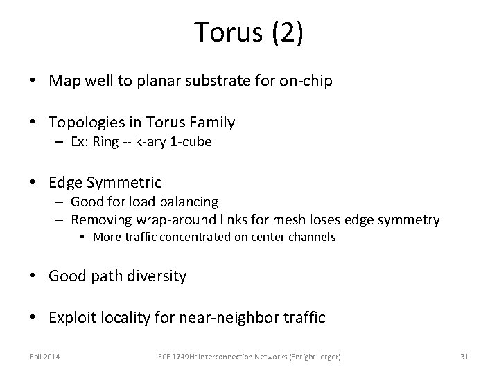
Torus (2) • Map well to planar substrate for on-chip • Topologies in Torus Family – Ex: Ring -- k-ary 1 -cube • Edge Symmetric – Good for load balancing – Removing wrap-around links for mesh loses edge symmetry • More traffic concentrated on center channels • Good path diversity • Exploit locality for near-neighbor traffic Fall 2014 ECE 1749 H: Interconnection Networks (Enright Jerger) 31
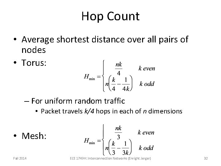
Hop Count • Average shortest distance over all pairs of nodes • Torus: – For uniform random traffic • Packet travels k/4 hops in each of n dimensions • Mesh: Fall 2014 ECE 1749 H: Interconnection Networks (Enright Jerger) 32
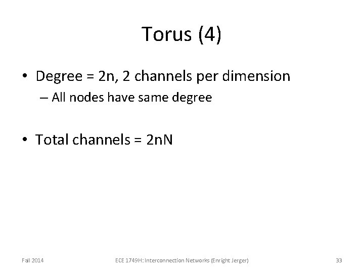
Torus (4) • Degree = 2 n, 2 channels per dimension – All nodes have same degree • Total channels = 2 n. N Fall 2014 ECE 1749 H: Interconnection Networks (Enright Jerger) 33
Channel Load for Torus • Even number of k-ary (n-1)-cubes in outer dimension • Dividing these k-ary (n-1)-cubes gives a 2 sets of kn-1 bidirectional channels or 4 kn-1 • ½ Traffic from each node cross bisection • Mesh has ½ the bisection bandwidth of torus Fall 2014 ECE 1749 H: Interconnection Networks (Enright Jerger) 34
Deriving Channel Load: 4 -ary 2 -cube • Divide network in half • Number of bisection channels – 8 links, bidirectional = 16 channels • ½ traffic crosses bisection • N/2 traffic distributed over 16 links • Channel load = ½ – Loaded at twice injection bandwidth Fall 2014 ECE 1749 H: Interconnection Networks (Enright Jerger) 35
Torus Path Diversity 2 dimensions* NW, NE, SW, SE combos 2 edge and node disjoint minimum paths *assume single direction for x and y Fall 2014 ECE 1749 H: Interconnection Networks (Enright Jerger) 36
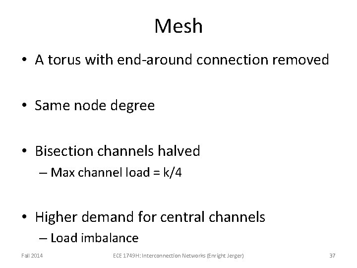
Mesh • A torus with end-around connection removed • Same node degree • Bisection channels halved – Max channel load = k/4 • Higher demand for central channels – Load imbalance Fall 2014 ECE 1749 H: Interconnection Networks (Enright Jerger) 37
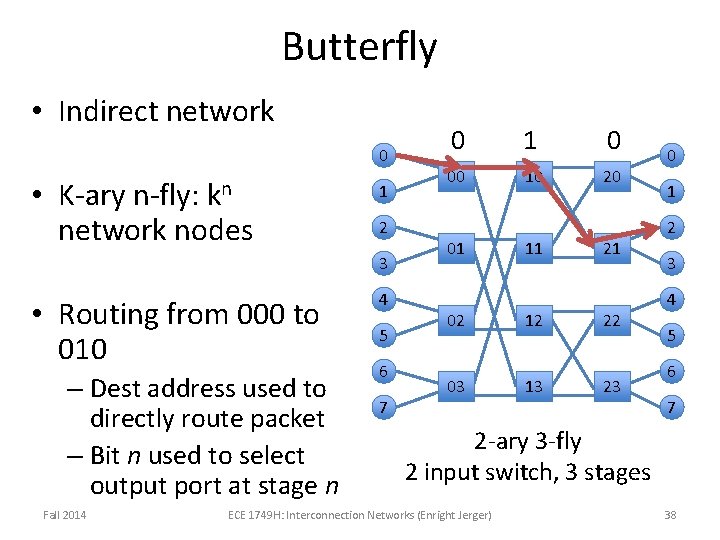
Butterfly • Indirect network 0 kn • K-ary n-fly: network nodes 1 2 3 • Routing from 000 to 010 – Dest address used to directly route packet – Bit n used to select output port at stage n Fall 2014 4 5 6 7 0 1 0 00 10 20 01 02 03 11 12 13 21 22 23 0 1 2 3 4 5 6 7 2 -ary 3 -fly 2 input switch, 3 stages ECE 1749 H: Interconnection Networks (Enright Jerger) 38
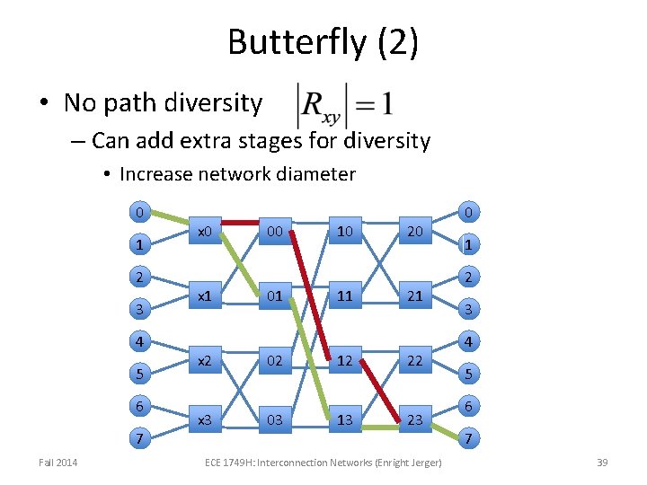
Butterfly (2) • No path diversity – Can add extra stages for diversity • Increase network diameter 0 1 2 3 4 5 6 7 Fall 2014 x 0 x 1 x 2 x 3 00 01 02 03 10 11 12 13 20 21 22 23 ECE 1749 H: Interconnection Networks (Enright Jerger) 0 1 2 3 4 5 6 7 39
Butterfly (3) • Hop Count – Logk. N + 1 – Does not exploit locality • Hop count same regardless of location • Switch Degree = 2 k • Requires long wires to implement Fall 2014 ECE 1749 H: Interconnection Networks (Enright Jerger) 40
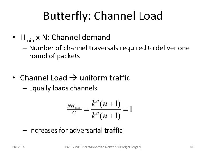
Butterfly: Channel Load • Hmin x N: Channel demand – Number of channel traversals required to deliver one round of packets • Channel Load uniform traffic – Equally loads channels – Increases for adversarial traffic Fall 2014 ECE 1749 H: Interconnection Networks (Enright Jerger) 41
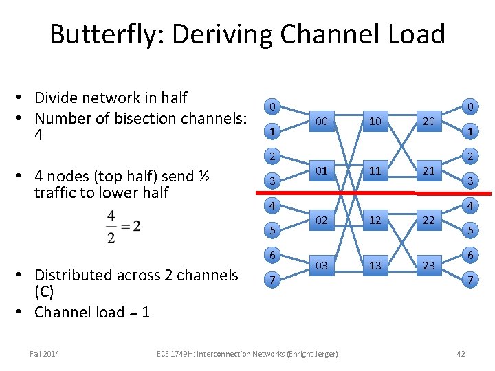
Butterfly: Deriving Channel Load • Divide network in half • Number of bisection channels: 4 0 1 2 • 4 nodes (top half) send ½ traffic to lower half 3 4 5 6 • Distributed across 2 channels (C) • Channel load = 1 Fall 2014 7 00 01 02 03 ECE 1749 H: Interconnection Networks (Enright Jerger) 10 11 12 13 0 20 1 2 21 3 4 22 5 6 23 7 42
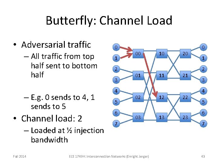
Butterfly: Channel Load • Adversarial traffic – All traffic from top half sent to bottom half – E. g. 0 sends to 4, 1 sends to 5 • Channel load: 2 – Loaded at ½ injection bandwidth Fall 2014 0 1 2 3 4 5 6 7 00 01 02 03 ECE 1749 H: Interconnection Networks (Enright Jerger) 10 11 12 13 20 21 22 23 0 1 2 3 4 5 6 7 43
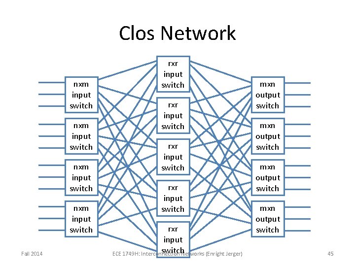
Clos Network • 3 -stage indirect network – Larger number of stages: built recursively by replacing middle stage with 3 -stage Clos • Characterized by triple (m, n, r) – M: # of middle stage switches – N: # of input/output ports on input/output switches – R: # of input/output switches • Hop Count = 4 Fall 2014 ECE 1749 H: Interconnection Networks (Enright Jerger) 44
Clos Network nxm input switch Fall 2014 rxr input switch rxr input switch. Networks (Enright Jerger) ECE 1749 H: Interconnection mxn output switch 45
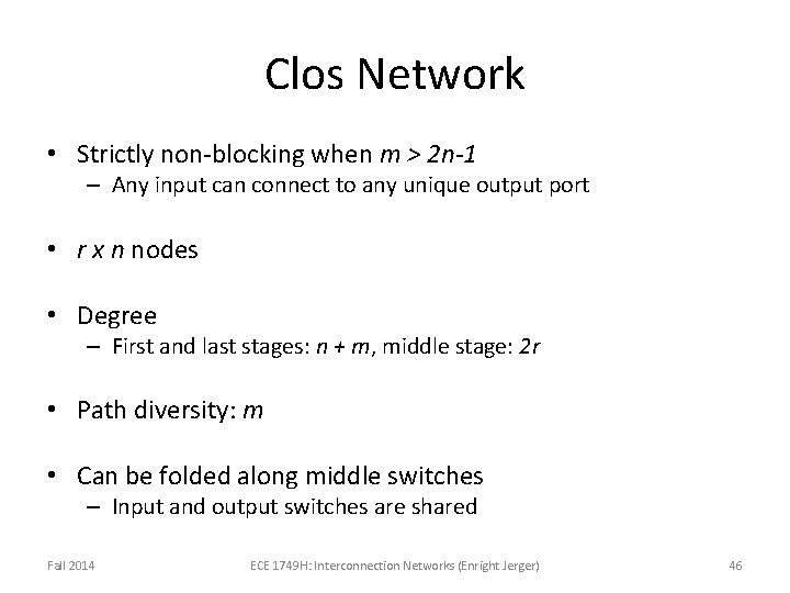
Clos Network • Strictly non-blocking when m > 2 n-1 – Any input can connect to any unique output port • r x n nodes • Degree – First and last stages: n + m, middle stage: 2 r • Path diversity: m • Can be folded along middle switches – Input and output switches are shared Fall 2014 ECE 1749 H: Interconnection Networks (Enright Jerger) 46
Folded Clos (Fat Tree) • Bandwidth remains constant at each level • Regular Tree: Bandwidth decreases closer to root Fall 2014 ECE 1749 H: Interconnection Networks (Enright Jerger) 47
Fat Tree (2) • Provides path diversity Fall 2014 ECE 1749 H: Interconnection Networks (Enright Jerger) 48
Application of Topologies to On-Chip Networks • FBFly – Convert butterfly to direct network • Swizzle switch – Circuit-optimized crossbar • Rings – Simple, low hardware cost • Mesh networks – Several products/prototypes • MECS and bus-based networks – Broadcast and multicast capabilities Fall 2014 ECE 1749 H: Interconnection Networks (Enright Jerger) 49
Implementation • Folding – Equalize path lengths • Reduces max link length • Increases length of other links Fall 2014 0 1 2 3 0 ECE 1749 H: Interconnection Networks (Enright Jerger) 3 2 1 50
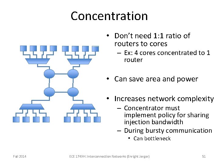
Concentration • Don’t need 1: 1 ratio of routers to cores – Ex: 4 cores concentrated to 1 router • Can save area and power • Increases network complexity – Concentrator must implement policy for sharing injection bandwidth – During bursty communication • Can bottleneck Fall 2014 ECE 1749 H: Interconnection Networks (Enright Jerger) 51
Implication of Abstract Metrics on Implementation • Degree: useful proxy for router complexity – Increasing ports requires additional buffer queues, requestors to allocators, ports to crossbar – All contribute to critical path delay, area and power – Link complexity does not correlate with degree • Link complexity depends on link width • Fixed number of wires, link complexity for 2 -port vs 3 port is same Fall 2014 ECE 1749 H: Interconnection Networks (Enright Jerger) 52
Implications (2) • Hop Count: useful proxy for overall latency and power – Does not always correlate with latency • Depends heavily on router pipeline and link propagation – Example: • Network A with 2 hops, 5 stage pipeline, 4 cycle link traversal vs. • Network B with 3 hops, 1 stage pipeline, 1 cycle link traversal Fall 2014 ECE 1749 H: Interconnection Networks (Enright Jerger) 53
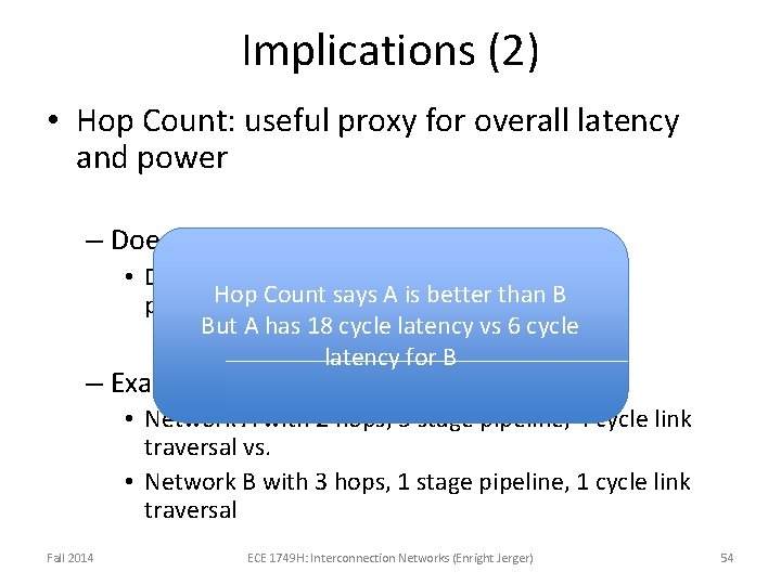
Implications (2) • Hop Count: useful proxy for overall latency and power – Does not always correlate with latency • Depends heavily on router pipeline and link Hop Count says A is better than B propagation But A has 18 cycle latency vs 6 cycle latency for B – Example: • Network A with 2 hops, 5 stage pipeline, 4 cycle link traversal vs. • Network B with 3 hops, 1 stage pipeline, 1 cycle link traversal Fall 2014 ECE 1749 H: Interconnection Networks (Enright Jerger) 54
Implications (3) • Topologies typically trade-off hop count and node degree • Max channel load useful proxy for network saturation and max power – Higher max channel load greater network congestion – Traffic pattern impacts max channel load • Representative traffic patterns important – Max power: dynamic power is highest with peak switching activity and utilization in network Fall 2014 ECE 1749 H: Interconnection Networks (Enright Jerger) 55
Topology Summary • First network design decision • Critical impact on network latency and throughput – Hop count provides first order approximation of message latency – Bottleneck channels determine saturation throughput Fall 2014 ECE 1749 H: Interconnection Networks (Enright Jerger) 56