Geographically Integrated Hydrologic Modeling Systems Interface data models


 Hydro Points Hydro Network (NHD)")


 GIS Script (Proc.")


- Slides: 41
Geographically Integrated Hydrologic Modeling Systems Interface data models GIS Model 1 Geo Database Arc Hydro data model Model 2 Model 3
Arc Hydro — Hydrography
Arc Hydro — Hydrology
Geographic Data Model • Conceptual Model – a set of concepts that describe a subject and allow reasoning about it • Mathematical Model – a conceptual model expressed in symbols and equations • Data Model – a conceptual model expressed in a data structure (Logical data model, physical data model) • Geographic Data Model – a data model expressed in a GIS database
Data Model based on Inventory of data layers
Data Model Based on Behavior “Follow a drop of water from where it falls on the land, to the stream, and all the way to the ocean. ” R. M. Hirsch, USGS
Arc Hydro Components Drainage System Hydro Network Flow Time Series Hydrography Channel System
Arc Hydro Framework Input Data Watersheds Waterbody Streams Hydro Points
Arc Hydro Framework Data Model
Arc Hydro Framework For South Florida Basins Waterbody (NHD) Hydro Points Hydro Network (NHD)
Nexrad Radar Rainfall Map
Extended Arc Hydro Framework for South Florida Hydro. Period Analysis Extended Arc Hydro Operations Decision Support System Arc Hydro Framework Regional Simulation Model Framework for South Florida Flood Modeling and Management
1. Define the Data Themes in the Core Model • Hydrographic lines • Water bodies • Drainage areas • Structures • Gages + ……. . Who will produce and verify these data? Will National Hydrography Dataset be used?
2. Define the ODSS GIS Framework • Select the ODSS waterbodies and structures from the core GIS framework • Integrate water control units in GIS • Define drainage area for each WCU • Build interface data model for ODSS • Build tools for 2 -way linkage between Arc. GIS and ODSS
Arc Hydro UML for ODSS WCU Schematic Link Water Control Network WCU Schematic Node Extended Arc Hydro Framework 1 1 Hydro. Junction 1 1. . * Water body 1. . * 1 Hydro. Edge network Subtypes Canal Segment Lake Subtypes Uncontrolled Controlled Junction Basin 1 Tidal Marsh 1. . * Monitoring. Point Structure 1. . *
• • • 3. Define the Flood Modeling Framework Define drainage areas, channels and control structures to be included Define flood simulation model(s) to be used Design Arc. GIS interface data model, if necessary Populate models with GIS data (Watershed analyst) Build tools for 2 -way linkage between Arc. GIS and Flood Models, if necessary
4. Define the RSM GIS Framework • Generalize GIS data needed for RSM (linear referencing and event themes) • Generate triangular mesh • Represent canal segments and pseudocells in GIS • Define Arc. GIS interface data model for RSM • Build tools for 2 -way linkage between Arc. GIS and RSM
5. Define GIS Functionality for Hydroperiod • Define conceptual framework • Convert to mathematical form • Define data structures needed • Build tools to execute model • Check against observed points to verify analysis • Train the District staff!
6. Build the District Arc Hydro Framework • Build the Hydro. Network • Connect the drainage areas • Connect the structures and monitoring points • Integrate other themes (e. g. District RSM mesh? )
7. Define the Water Inputs • Connect to the Nexrad data • Connect to db. Hydro for gage information • Satellite information? • Climate information? • Water quality?
8. Build Information Flows Among Applications Hydro. Period Analysis Extended Arc Hydro Operations Decision Support System Arc Hydro Framework Regional Simulation Model Framework for South Florida Flood Modeling and Management
Regional Storm Water Modeling Program and Master Plan for San Antonio
Regional Watershed Modeling Master Plan Goals • Develop new or incorporate existing hydrology, hydraulic and water quality models (“Bring the models together”) • Provide GIS-based interfaces for models • Provide for maintenance of models and geospatial data • Develop standards for modeling and geospatial data • Regional Watershed Modeling System to assist in: – flood mitigation planning – capital project prioritization
San Antonio Regional Watershed Modeling System Geospatial Data: City, County SARA, other Rainfall Data: Rain gages Nexrad Floodplain Management Modeling System Calibration Data: Flows Water Quality Capital Water quality Improvement planning Planning Integrated Flood Regional Water Forecasting Resources planning
Arc Hydro and HEC-HMS Hydrologic Model Arc Hydro Schematic Network Calculates Flows
Arc Hydro and HEC-RAS Arc Hydro Channel Cross Sections HEC-RAS Hydraulic Model Calculates Water Surface Elevations
Flow Change Points Models communicate with one another through Arc Hydro at designated points
Nexrad Map to Flood Map in FLO Model Builder ODP Flood map as output LAIN MAP Model for flood flow HMS Nexrad map as input Model for flood depth
Hydrologic Modeling within Arc. GIS • Reverse engineer the parameter values from calibrated hydrologic simulation models into the interface data model • Lib. Hydro – a library of hydrologic processing functions callable as a dll • Schematic network processor to execute functions in the right order
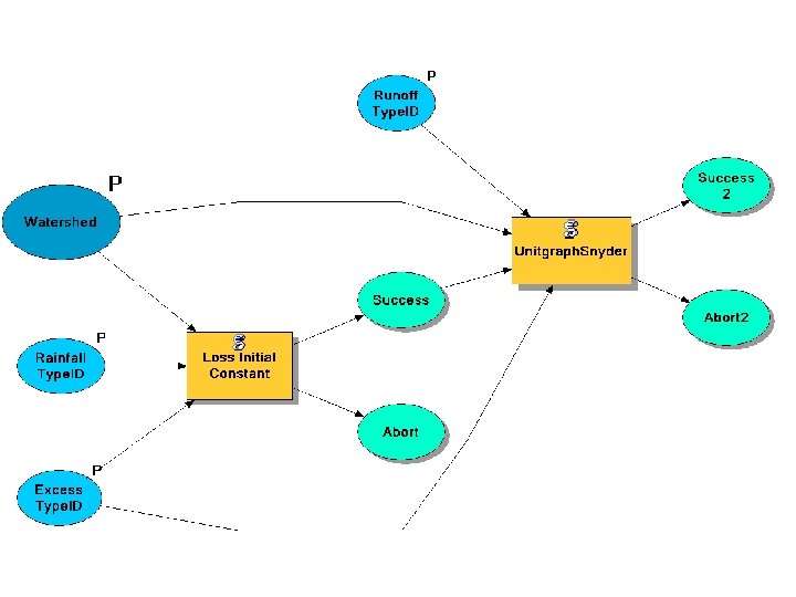
Schematic Network • Standard Arc Hydro data structure – Schematic Links – Schematic Nodes • Type 1 Nodes and Links for Watersheds • Type 2 Nodes and Links for Streams • Type 3 for …. .
Schematic Network Processes • Node processes – Rainfall-runoff and pollutant loads on watersheds – Summing flows or loads on streams – Water quality in water bodies • Link processes – Routing flows in streams – Pollutant losses in streams
Lib. Hydro • A Fortran subroutine library of hydrologic processes developed from HEC-1 • Packaged in Lib. Hydro. DLL for operation under Visual Basic • Transforms input time series to output time series • More details on GISHydro 2003 CD
Excess Calculation • Initial Loss and Constant Loss Rate function Pick up a watershed Hydro. ID = 2346 Impervious. Area. Ratio = 0. 0001 Initial. Loss = 1. 6 (mm) Constant. Loss. Rate = 0. 38 (mm) Simulation Period: 7/21/97 – 7/23/97 (3 days) Time Interval: 15 minutes Time step: 4 * 24(hour) * 3(days) = 288
Runoff Calculation • Snyder Unit Hydrograph Pick up a watershed Watershed area: 266. 5 (km 2) Snyder. Cp: 0. 8 Snyder. Tp: 5. 58 (hr) Simulation Period: 7/21/97 – 7/23/97 (3 days) Time Interval: 15 minutes
Outflow Calculation • Add Baseflow module • Outflow = runoff + baseflow • Recession Ratio = 0. 95, Threshold value = 2 (m 3/s)
Looping Through the Schematic Network Get Upstream Features Upstream Hydro. IDs Hydro. ID Topology Collection Feature, Values Get Upstream Values Process Upstream Values Receive Processed Value Collection Hydro. ID, New Value Update Value Collection See GISHydro 2003 CD for details Process Value to Pass Feature, Value Processed Value Pass Process
Schematic Network Process Implementation Geodatabase Arc. Toolbox Script Tool (Process. Schematic) GIS Script (Proc. Schematic. vbs) DLL (MBSchematic. dll) Script and DLLs Process DLL 1 Process DLL n
Strengths of Arc. GIS for Modeling • Integration with the COM environment, use of Visual Basic, and accessibility of models through dlls is great step forward • Network topology a big help for water resources networks • Geodatabase design process is important for modeling system architecture • Model Builder is great for handling work flow sequences
Limitations of Arc. GIS for Modeling • No data model and tools for time series in core software • Graph plotting is inadequate for displaying time series • Relationships are critical in geodatabase design but can’t be created in Arc. View – separate toolkits for Arc. Info and Arc. View implementation of modeling systems? • No scheme for scenario management
Overall Assessment • Geographic framework: solid • Model connections: good architecture, needs development • Time series: being improved with current research Hydrologic Information System