
Introduction to Integrated Control Systems Timo Korhonen ICS


- Slides: 28
Introduction to Integrated Control Systems Timo Korhonen ICS ESS/ICS Date: 2016 -04
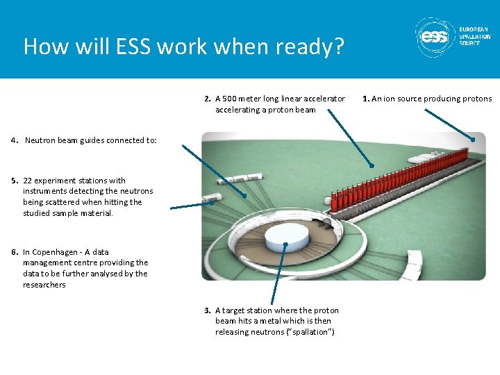
How will ESS work when ready? 2. A 500 meter long linear accelerator accelerating a proton beam 4. Neutron beam guides connected to: 5. 22 experiment stations with instruments detecting the neutrons being scattered when hitting the studied sample material. 6. In Copenhagen - A data management centre providing the data to be further analysed by the researchers 3. A target station where the proton beam hits a metal which is then releasing neutrons (“spallation”) 1. An ion source producing protons
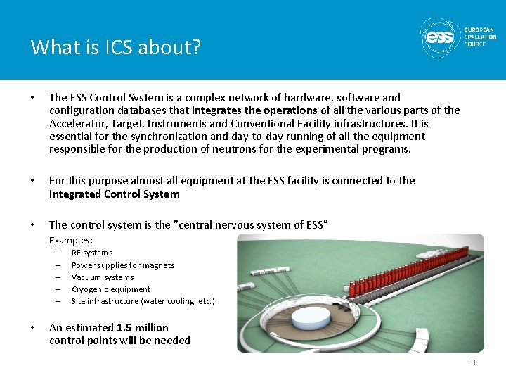
What is ICS about? • The ESS Control System is a complex network of hardware, software and configuration databases that integrates the operations of all the various parts of the Accelerator, Target, Instruments and Conventional Facility infrastructures. It is essential for the synchronization and day-to-day running of all the equipment responsible for the production of neutrons for the experimental programs. • For this purpose almost all equipment at the ESS facility is connected to the Integrated Control System • The control system is the ”central nervous system of ESS” Examples: – – – • RF systems Power supplies for magnets Vacuum systems Cryogenic equipment Site infrastructure (water cooling, etc. ) An estimated 1. 5 million control points will be needed 3
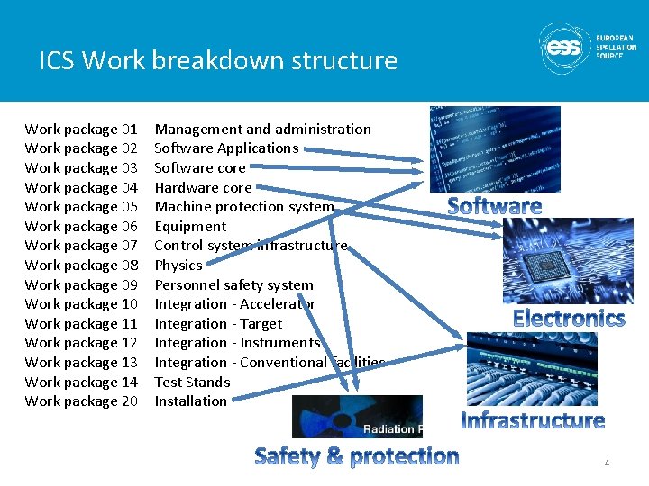
ICS Work breakdown structure Work package 01 Work package 02 Work package 03 Work package 04 Work package 05 Work package 06 Work package 07 Work package 08 Work package 09 Work package 10 Work package 11 Work package 12 Work package 13 Work package 14 Work package 20 Management and administration Software Applications Software core Hardware core Machine protection system Equipment Control system infrastructure Physics Personnel safety system Integration - Accelerator Integration - Target Integration - Instruments Integration - Conventional facilities Test Stands Installation 4
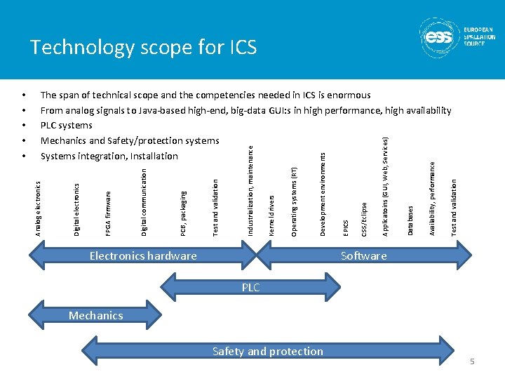
Technology scope for ICS Electronics hardware Test and validation Availability, performance Databases Applicatoins (GUI, Web, Services) CSS/Eclipse EPICS Development environments Operating systems (RT) Kernel drivers Industrialization, maintenance Test and validation PCB, packaging Digital communication FPGA firmware Digital electronics The span of technical scope and the competencies needed in ICS is enormous From analog signals to Java-based high-end, big-data GUI: s in high performance, high availability PLC systems Mechanics and Safety/protection systems Systems integration, Installation Analog electronics • • • Software PLC Mechanics Safety and protection 5
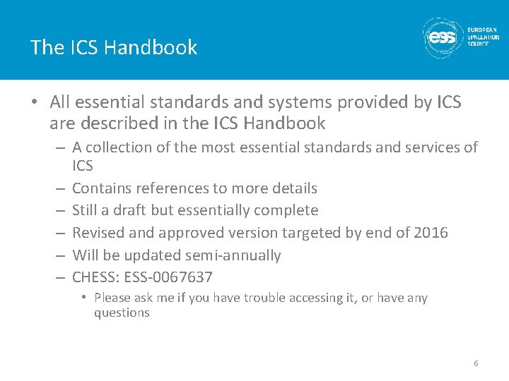
The ICS Handbook • All essential standards and systems provided by ICS are described in the ICS Handbook – A collection of the most essential standards and services of ICS – Contains references to more details – Still a draft but essentially complete – Revised and approved version targeted by end of 2016 – Will be updated semi-annually – CHESS: ESS-0067637 • Please ask me if you have trouble accessing it, or have any questions 6
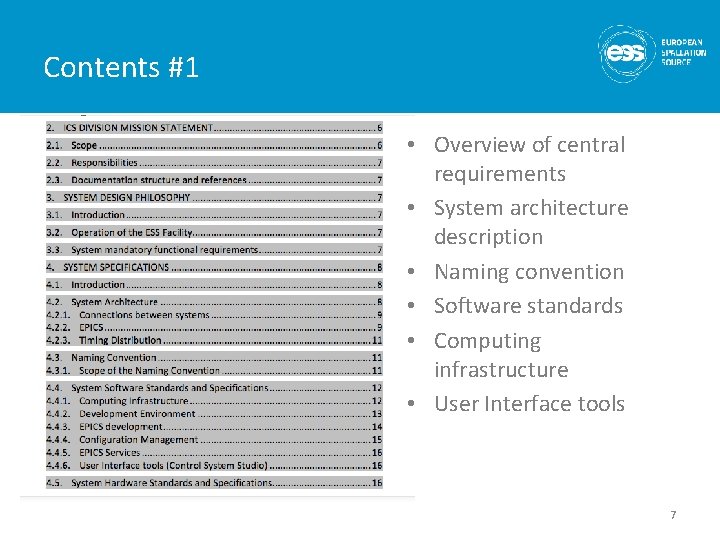
Contents #1 • Overview of central requirements • System architecture description • Naming convention • Software standards • Computing infrastructure • User Interface tools 7
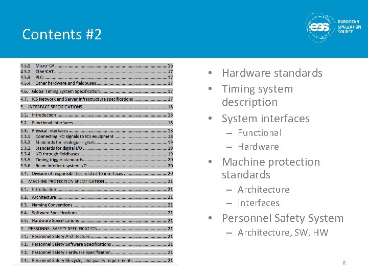
Contents #2 • Hardware standards • Timing system description • System interfaces – Functional – Hardware • Machine protection standards – Architecture – Interfaces • Personnel Safety System – Architecture, SW, HW 8
9
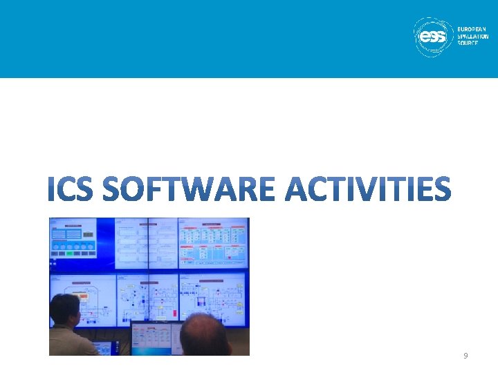
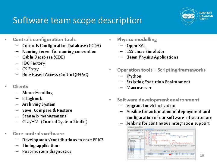
Software team scope description • Controls configuration tools – – – • Alarm Handling E-logbook Archiving System Save, Compare & Restore Scenario management GUI/HMI (Control System Studio) Physics modelling – Open XAL – ESS Linac Simulator – Beam Physics Applications • Operation tools – Scripting frameworks – i. Python – Scripting Execution Environment – Macroserver Clients – – – • Controls Configuration Database (CCDB) Naming Server for naming convention Cable Database (CDB) IOC Factory CS Entry Role Based Access Control (RBAC) • • Software development environment – Vagrant for virtualization – Ansible for automation of deployment and configuration of our software infrastructure – Jenkins for continuous integration support Core controls software – Development/contributions to core EPICS – Timing applications – Post-mortem diagnostics 10
11
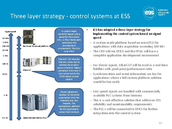
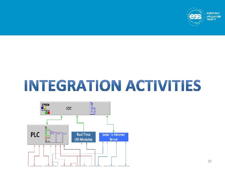
Three layer strategy - control systems at ESS Signal speed 10 MHz 100 k. Hz Electronic front-end platform 10 k. Hz A custom made micro. TCA board with a powerful FPGA and a CPU. A FPGA framework constitutes the development environment. The CPU runs EPICS 1 k. Hz 100 Hz Ether. CAT 10 Hz Slower signals are handled by industrial automation (PLC) for reliability and cost reasons. The standardized platform for ESS applications comes from Siemens 1 Hz 0. 1 Hz Ether. CAT I/O modules that are connected to commercial or opensource Ether. CAT master controllers which are in turn connected to the EPICS based control system • ICS has adopted a three layer strategy for implementing the control system based on signal speed – A custom made platform based on micro. TCA for applications with data acquisition exceeding 100 k. Hz – The CPU will run EPICS and the FPGA will have a complete application development environment – For slower signals, Ether. CAT will be used as a real-time fieldbus with good price/performance ratio – Synchronization and event information are key for applications where a full custom platform solution would be too costly – Low speed signals are handled with commercially available PLC systems from Siemens – This is a cost-effective solution that addresses ESS reliability and maintainability requirements – The PLC: s will be connected to EPICS for further integration into the control system Industrial automation (PLC) 12
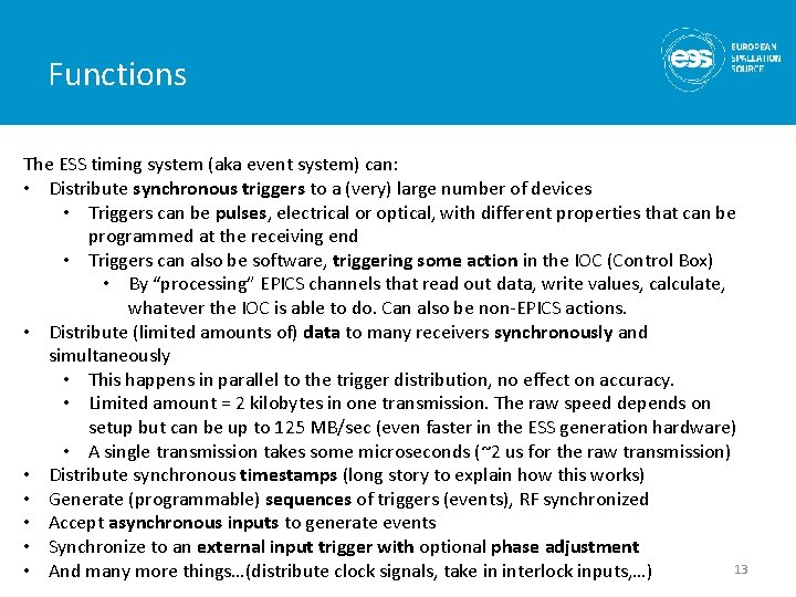
Functions The ESS timing system (aka event system) can: • Distribute synchronous triggers to a (very) large number of devices • Triggers can be pulses, electrical or optical, with different properties that can be programmed at the receiving end • Triggers can also be software, triggering some action in the IOC (Control Box) • By “processing” EPICS channels that read out data, write values, calculate, whatever the IOC is able to do. Can also be non-EPICS actions. • Distribute (limited amounts of) data to many receivers synchronously and simultaneously • This happens in parallel to the trigger distribution, no effect on accuracy. • Limited amount = 2 kilobytes in one transmission. The raw speed depends on setup but can be up to 125 MB/sec (even faster in the ESS generation hardware) • A single transmission takes some microseconds (~2 us for the raw transmission) • Distribute synchronous timestamps (long story to explain how this works) • Generate (programmable) sequences of triggers (events), RF synchronized • Accept asynchronous inputs to generate events • Synchronize to an external input trigger with optional phase adjustment 13 • And many more things…(distribute clock signals, take in interlock inputs, …)
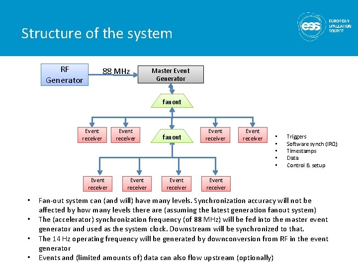
Structure of the system RF Generator 88 MHz Master Event Generator fanout Event receiver • • Event receiver fanout Event receiver • • • Triggers Software synch (IRQ) Timestamps Data Control & setup Event receiver Fan-out system can (and will) have many levels. Synchronization accuracy will not be affected by how many levels there are (assuming the latest generation fanout system) The (accelerator) synchronization frequency (of 88 MHz) will be fed into the master event generator and used as the system clock. Downstream will be synchronized to that. The 14 Hz operating frequency will be generated by downconversion from RF in the event generator Events and (limited amounts of) data can also flow upstream (optionally)
15
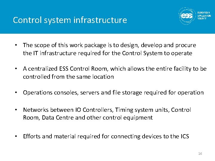
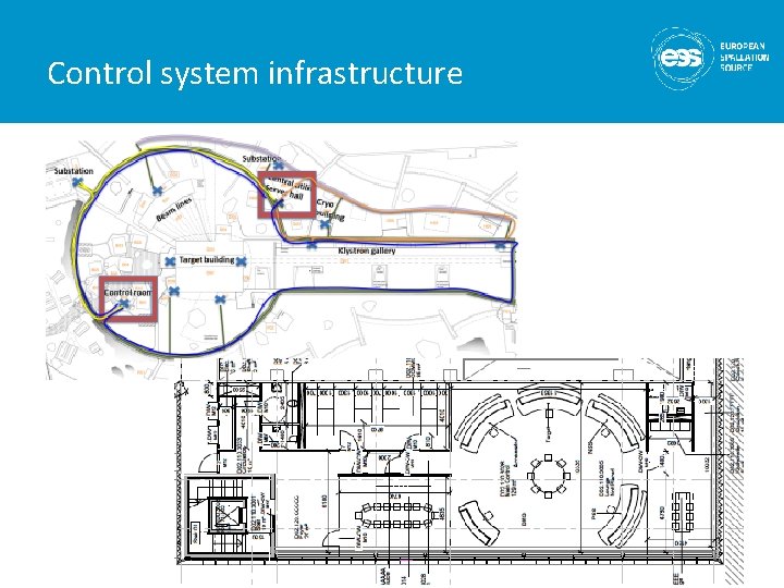
Control system infrastructure • The scope of this work package is to design, develop and procure the IT infrastructure required for the Control System to operate • A centralized ESS Control Room, which allows the entire facility to be controlled from the same location • Operations consoles, servers and file storage required for operation • Networks between IO Controllers, Timing system units, Control Room, Data Centre and other control equipment • Efforts and material required for connecting devices to the ICS 16
Control system infrastructure
18
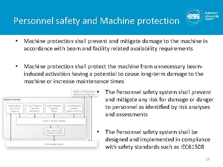
Personnel safety and Machine protection • Machine protection shall prevent and mitigate damage to the machine in accordance with beam and facility related availability requirements • Machine protection shall protect the machine from unnecessary beaminduced activation having a potential to cause long-term damage to the machine or increase maintenance times • The Personnel safety system shall prevent and mitigate any risk for damage or danger to personnel as identified by risk analyses and assessments • The Personnel safety system shall be designed and implemented in compliance with safety standards such as IEC 61508 19
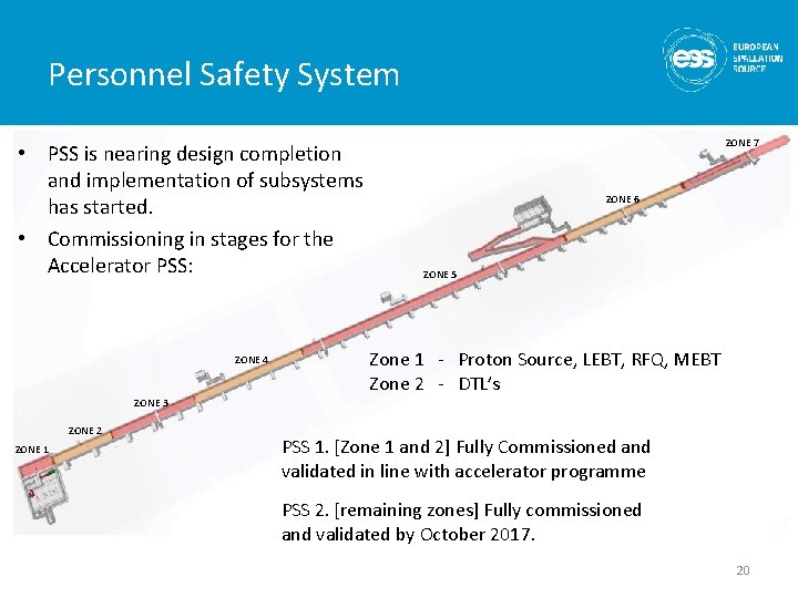
Personnel Safety System • PSS is nearing design completion and implementation of subsystems has started. • Commissioning in stages for the Accelerator PSS: ZONE 4 ZONE 7 ZONE 6 ZONE 5 Zone 1 - Proton Source, LEBT, RFQ, MEBT Zone 2 - DTL’s ZONE 3 ZONE 2 ZONE 1 PSS 1. [Zone 1 and 2] Fully Commissioned and validated in line with accelerator programme PSS 2. [remaining zones] Fully commissioned and validated by October 2017. 20
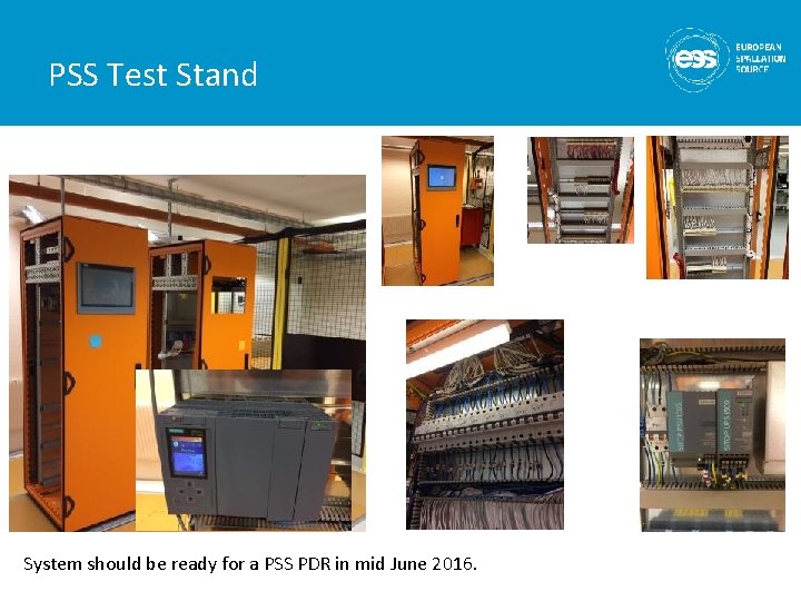
PSS Test Stand System should be ready for a PSS PDR in mid June 2016.
22
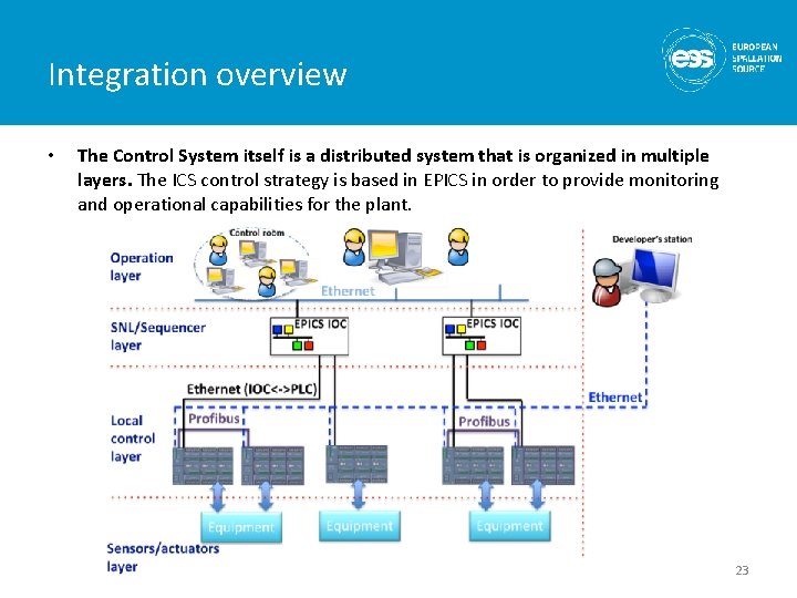
Integration overview • The Control System itself is a distributed system that is organized in multiple layers. The ICS control strategy is based in EPICS in order to provide monitoring and operational capabilities for the plant. 23
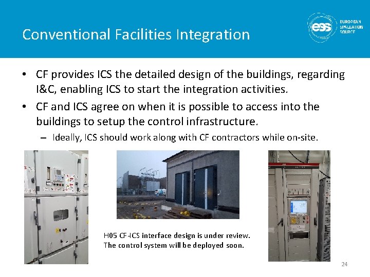
Conventional Facilities Integration • CF provides ICS the detailed design of the buildings, regarding I&C, enabling ICS to start the integration activities. • CF and ICS agree on when it is possible to access into the buildings to setup the control infrastructure. – Ideally, ICS should work along with CF contractors while on-site. H 05 CF-ICS interface design is under review. The control system will be deployed soon. 24
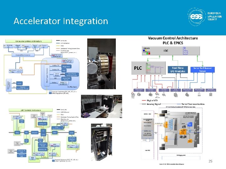
Accelerator Integration 25
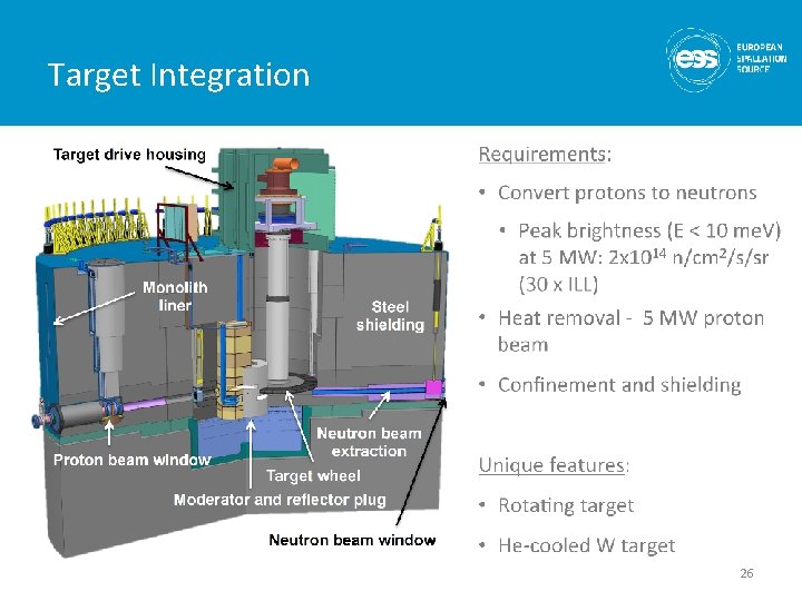
Target Integration 26
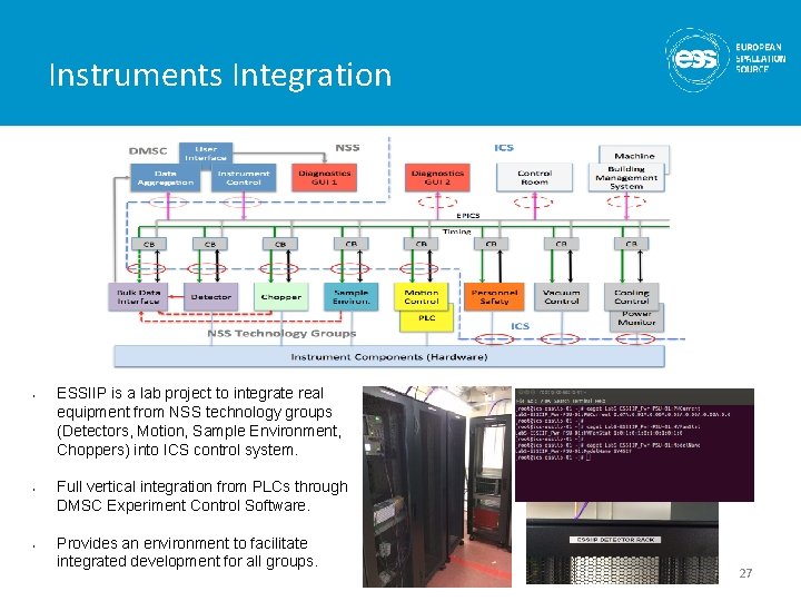
Instruments Integration • • • ESSIIP is a lab project to integrate real equipment from NSS technology groups (Detectors, Motion, Sample Environment, Choppers) into ICS control system. Full vertical integration from PLCs through DMSC Experiment Control Software. Provides an environment to facilitate integrated development for all groups. 27
28