US Army Corps of Engineers Hydrologic Engineering Center


- Slides: 28

US Army Corps of Engineers Hydrologic Engineering Center River Mechanics and Introduction to Unsteady Flow Equations • Objective: Present key items for switching from HEC-RAS steady flow analysis to HEC-RAS unsteady flow simulation. Michael Gee, Ph. D, PE Senior Hydraulic Engineer

Steady vs. Unsteady • Difference in handling friction and other losses • Difference in numerical solution algorithm • Difference in computation of X-Sec properties • Difference in handling non-flow areas • Difference in flow and boundary condition data requirements • Difference in calibration strategy • Difference in application strategy

Energy Principles Energy Water Surfac Grade Line he e Y 2 Cha nne l Bo ttom Y 1 Z 2 Datum Z 1

Momentum Equation Fx = m a 2 1 P 2 W Wx Z 2 Datum Ff P 1 L Z 1

Momentum Equation P 2 - P 1 + W x - F f = Q Δ V x Where: P = Hydrostatic Pressure Wx = Force due to weight of water in X direction Ff = Force due to external friction from 2 to 1 Q = Discharge = Density of water Δ Vx = Change in velocity from 2 to 1 in X direction

Momentum Equation – Forces Pressure: Weight: Friction: Mass x acceleration: Where:

Energy vs. Momentum • Energy – Internal energy dissipation represented by loss term, Sf (Manning’s n) • Momentum – External boundary shear forces represented by friction term, Sf (Manning’s n)

Unsteady Flow Equations Momentum Equation: Continuity Equation:

Steady Flow Equations Energy (momentum) Equation: Continuity Equation:

Numerical Solution Friction slope averaging Steady: Average conveyance Unsteady: Average friction slope

Average conveyance Eq. Average friction slope Eq.


Numerical Solution Algorithms used Steady: Iterative convergence section-by-section for each flow. Unsteady: Matrix solution for flow and stage simultaneously at all sections each time step.

Numerical Solution of the Unsteady Flow Equations CONVERGENCE The state of tending to a unique solution. A given scheme is convergent if an increasingly finer computational grid leads to a more accurate solution. STABILITY (NUMERICAL or COMPUTATIONAL) The ability of a scheme to control the propagation or growth of small perturbations introduced in the calculations. A scheme is unstable if it allows the growth of error to eventually obliterate the true solution. Ref: River Hydraulics EM

Courant Number For best results, the Cr should be near 1. 0

Courant Number Example • Depth ~ 10 ft. • Cross section spacing ( x) of ~ 1000 ft. • Requires computational time step ( t) about 1 minute

Finite Difference Modeling Considerations 1. Stability of the computations. 2. 2. Numerical accuracy of the computations. 3. 3. Resolution of input hydrographs.

Pre-Computation of Hydraulic Properties (CSECT or HTAB) Steady – Compute exact hydraulic properties at a section for each trial water surface elevation from the GR points, n-values, etc. Unsteady – Hydraulic properties are pre-computed for all possible water surface elevations at each cross section (HTAB)

Non-Flow Areas Steady – “ineffective” areas may or may not be occupied by water. Unsteady – All areas containing water (even if not moving) must be included.

Expansion/Contraction Coeffs. • Not used in the momentum formulation (RAS-unsteady) • Should be in the data, however, for use with steady flow analysis

Data Requirements (Flow and Boundary Conditions) Steady: Discharge (Q) at each cross section. Unsteady: Inflow hydrograph(s) which are routed by the model.

Calibration Strategy – Targets Steady: Match observed water surface (or EGL) elevations. Unsteady: As above, along with timing, hydrograph shape, computed flow distribution in networks.

Calibration Strategy Adjustments Steady: Manning’s n Unsteady: n and volume (storage); make adjustments throughout range of flows in hydrograph. Add/subtract flows if necessary.

Flow Accounting Q Observed outflow 2 Inflow Observed outflow 1 Computed outflow Time

Application Strategy 1. Check with range of steady flows Rough stage calibration. Possible supercritical flow locations. Modeling of hydraulic structures.

2. Prepare hydrographs (boundary conditions) Upstream flows Tributary (local flows) Ungaged/unmodeled flows Downstream (rating curve? )

3. Calibration Manning’s n affects both stage and timing. Storage areas can be very important. Fine tuning via conveyance adjustment.

QUESTIONS?
 Groundwater modeling
 Army corps of engineers baltimore
 Hydrologic engineering center
 Hydrologic engineering center
 River analysis system
 Hydrologic engineering center
 Navy supply officer career path
 Hec-2 download
 Types of flood routing
 Hydrologic routing
 Hydrologic losses
 Hydrologic equation
 Hydrologic abstractions
 Hydrologic continuity equation
 Rickley hydrologic
 Continuity equation hydraulics
 Water cycle the hydrologic cycle
 Applied hydrology
 Usachcs training
 Engineering ethics in practice a guide for engineers
 Engineering ethics in practice a guide for engineers
 Blue ridge job corps
 Center for army analysis
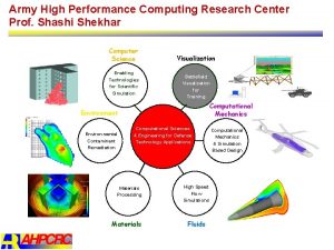
 Army high performance computing research center
 Computer based system engineering in software engineering
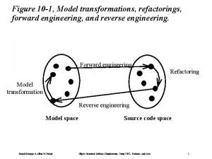
 Forward engineering in software engineering
 Engineering elegant systems: theory of systems engineering
 Elegant systems
 Reverse engineering vs forward engineering
