Experiments With Resistors Measuring Resistors The Resistor Color


- Slides: 25
Experiments With Resistors Measuring Resistors The Resistor Color Code A Simple Resistor Experiment Measuring Resistor Accuracy Resistor Combinations Series Resistors Parallel Resistors
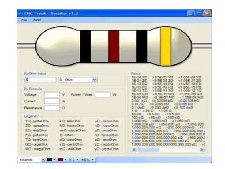
• Measuring Resistances • Let's start by making one resistance measurement. • Get a resistor of a one k-ohm as an example. You can tell it is a 1 k-ohm resistor by the color stripes. They should be brown-black-red in that order from the end, as shown in fig on next page.
• You are now ready to measure the resistance. Connect your resistor to an ohmmeter as shown in figure. Don't care about the lead on which end of the resistor. It doesn't latter. (The resistor is a bilateral element and should be the same either way), here are the connections you make.
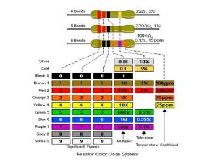
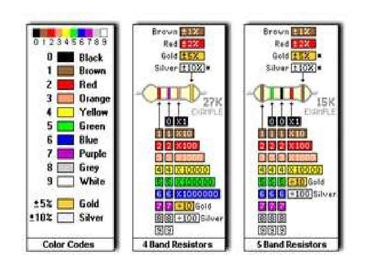
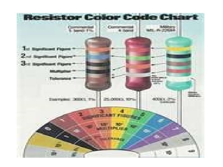
• The Resistor Color Code • You probably wondered about those stripes on the resistor. There is a color code that lets you tell what value the resistor has. Here's what's important. • This resistor is 1000 ohms = 10 x 102
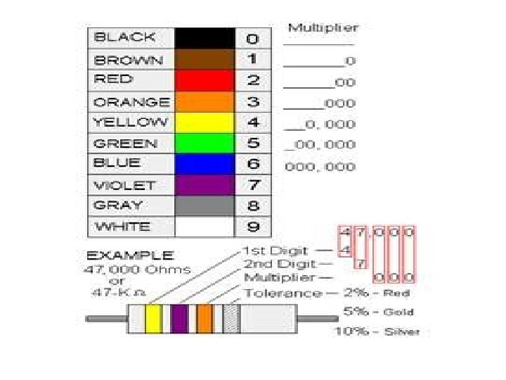
0 Black 1 Brown 2 Red 3 Orange 4 Yellow 5 Green 6 Blue 7 Violet 8 Gray 9 White ± 10% Silver ± 5% Gold ± 20% Black
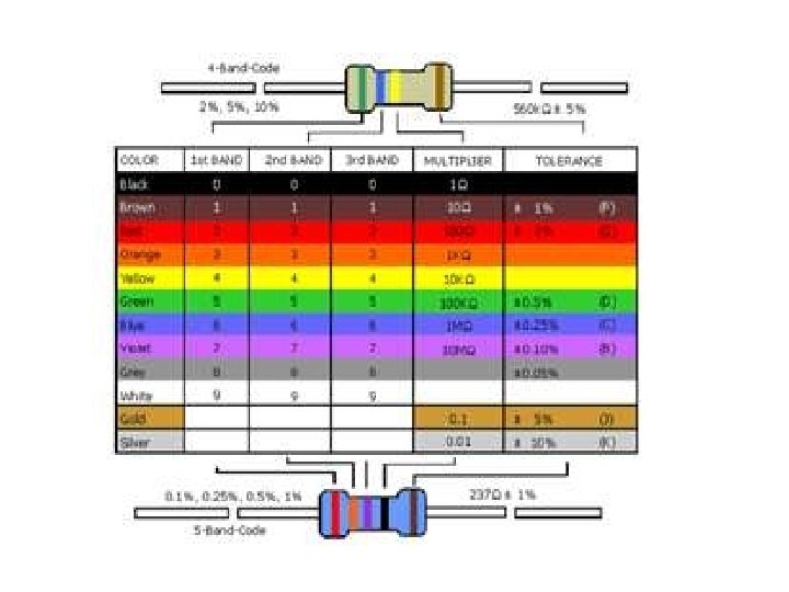
Tolerance band • The tolerance band is typically either gold or silver. A gold tolerance band indicates that the measured value will be within 5% of the nominal value. A silver band indicates 10% tolerance. For example a resistor with color code brown-blackred-silver indicates a nominal value of 1 k. • The first two bands (brown-black) produce the mantissa (10) and the third band (red) is the exponent of ten (x 10). Since the tolerance band is silver, we can expect the measured value of the resistor to be between (900 and 1100)ohm.
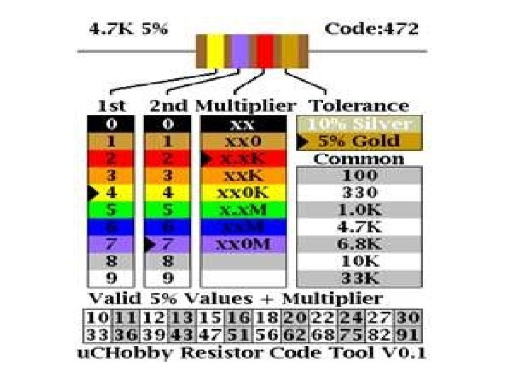
To calculate the value of the resistance you use three stripes. (If there are four stripes, just use the first three. The last stripe tells you how accurate the resistance value is). Here is the algorithm.
Algorithm • The first strip is the left-most significant digit, X, in XY x 10 N • The second strip is the next digit, Y, in XY x 10 N • The third strip is the exponent in XY x 10 N Where N represents the Code of the color
A Simple Resistor • Any conducting material can be used to make a resistor. Any metal or metallic alloy can be used. Other conducting materials, like carbon, germanium or silicon can be used, even if the material does not conduct as well as a metal. In this exercise you are going to construct some resistors made of carbon.
The carbon you will use is the carbon found in a pencil lead. On a clean sheet of paper draw a shape like the one below. It can be smaller but drawn to scale. You have just constructed and measured a resistor. There is a special symbol for a resistor that you need to become familiar with. Here it is.
• The diagonal lines are intended to suggest some resistance to the flow of current. This symbol can be used in any orientation, and you will often see this symbol rotated as shown at the right.
When you measured your resistor the ohmmeter that you used actually applied a small voltage across your resistor and current flowed through it. Often symbols are attached to the resistor symbol to indicate how the voltage is applied across the resistor and to define a positive direction for current flow. In a case where both a current and a voltage symbol were used the situation would look like what we have shown on last page.
• The second resistor should be the same physical size as the original resistor. Since it is the same size and made of the same material it should have the same resistance. There are physical reasons why that is so, and there is a mathematical expression that relates the resistance to length, cross sectional area and a property of the material called resistivity. • For resistors that have a constant cross section, A, and a length, L, the resistance is: R = r. L/A
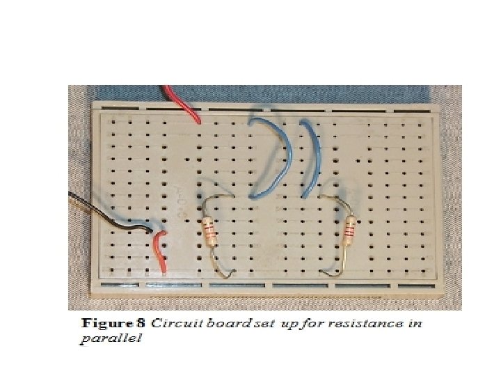
Now that you have the two same resistors to measure, go ahead and measure the series combination. When you have that measurement taken and you think you are close enough to the correct measured value you can go on.
Breadboard
Example of Components connections
Shapes of different components